EP4015193A1 - Appareil et procédé de formation d'un film pour étui pour une batterie secondaire - Google Patents
Appareil et procédé de formation d'un film pour étui pour une batterie secondaire Download PDFInfo
- Publication number
- EP4015193A1 EP4015193A1 EP20878181.5A EP20878181A EP4015193A1 EP 4015193 A1 EP4015193 A1 EP 4015193A1 EP 20878181 A EP20878181 A EP 20878181A EP 4015193 A1 EP4015193 A1 EP 4015193A1
- Authority
- EP
- European Patent Office
- Prior art keywords
- pouch film
- pouch
- shaping
- barrier layer
- preheating
- Prior art date
- Legal status (The legal status is an assumption and is not a legal conclusion. Google has not performed a legal analysis and makes no representation as to the accuracy of the status listed.)
- Granted
Links
Images

Classifications
-
- B—PERFORMING OPERATIONS; TRANSPORTING
- B29—WORKING OF PLASTICS; WORKING OF SUBSTANCES IN A PLASTIC STATE IN GENERAL
- B29C—SHAPING OR JOINING OF PLASTICS; SHAPING OF MATERIAL IN A PLASTIC STATE, NOT OTHERWISE PROVIDED FOR; AFTER-TREATMENT OF THE SHAPED PRODUCTS, e.g. REPAIRING
- B29C59/00—Surface shaping of articles, e.g. embossing; Apparatus therefor
- B29C59/002—Component parts, details or accessories; Auxiliary operations
-
- H—ELECTRICITY
- H01—ELECTRIC ELEMENTS
- H01M—PROCESSES OR MEANS, e.g. BATTERIES, FOR THE DIRECT CONVERSION OF CHEMICAL ENERGY INTO ELECTRICAL ENERGY
- H01M50/00—Constructional details or processes of manufacture of the non-active parts of electrochemical cells other than fuel cells, e.g. hybrid cells
- H01M50/10—Primary casings; Jackets or wrappings
- H01M50/102—Primary casings; Jackets or wrappings characterised by their shape or physical structure
- H01M50/105—Pouches or flexible bags
-
- B—PERFORMING OPERATIONS; TRANSPORTING
- B21—MECHANICAL METAL-WORKING WITHOUT ESSENTIALLY REMOVING MATERIAL; PUNCHING METAL
- B21D—WORKING OR PROCESSING OF SHEET METAL OR METAL TUBES, RODS OR PROFILES WITHOUT ESSENTIALLY REMOVING MATERIAL; PUNCHING METAL
- B21D22/00—Shaping without cutting, by stamping, spinning, or deep-drawing
- B21D22/02—Stamping using rigid devices or tools
- B21D22/022—Stamping using rigid devices or tools by heating the blank or stamping associated with heat treatment
-
- B—PERFORMING OPERATIONS; TRANSPORTING
- B21—MECHANICAL METAL-WORKING WITHOUT ESSENTIALLY REMOVING MATERIAL; PUNCHING METAL
- B21D—WORKING OR PROCESSING OF SHEET METAL OR METAL TUBES, RODS OR PROFILES WITHOUT ESSENTIALLY REMOVING MATERIAL; PUNCHING METAL
- B21D37/00—Tools as parts of machines covered by this subclass
- B21D37/16—Heating or cooling
-
- B—PERFORMING OPERATIONS; TRANSPORTING
- B29—WORKING OF PLASTICS; WORKING OF SUBSTANCES IN A PLASTIC STATE IN GENERAL
- B29C—SHAPING OR JOINING OF PLASTICS; SHAPING OF MATERIAL IN A PLASTIC STATE, NOT OTHERWISE PROVIDED FOR; AFTER-TREATMENT OF THE SHAPED PRODUCTS, e.g. REPAIRING
- B29C59/00—Surface shaping of articles, e.g. embossing; Apparatus therefor
- B29C59/02—Surface shaping of articles, e.g. embossing; Apparatus therefor by mechanical means, e.g. pressing
-
- B—PERFORMING OPERATIONS; TRANSPORTING
- B29—WORKING OF PLASTICS; WORKING OF SUBSTANCES IN A PLASTIC STATE IN GENERAL
- B29C—SHAPING OR JOINING OF PLASTICS; SHAPING OF MATERIAL IN A PLASTIC STATE, NOT OTHERWISE PROVIDED FOR; AFTER-TREATMENT OF THE SHAPED PRODUCTS, e.g. REPAIRING
- B29C65/00—Joining or sealing of preformed parts, e.g. welding of plastics materials; Apparatus therefor
- B29C65/02—Joining or sealing of preformed parts, e.g. welding of plastics materials; Apparatus therefor by heating, with or without pressure
- B29C65/14—Joining or sealing of preformed parts, e.g. welding of plastics materials; Apparatus therefor by heating, with or without pressure using wave energy, i.e. electromagnetic radiation, or particle radiation
- B29C65/1403—Joining or sealing of preformed parts, e.g. welding of plastics materials; Apparatus therefor by heating, with or without pressure using wave energy, i.e. electromagnetic radiation, or particle radiation characterised by the type of electromagnetic or particle radiation
- B29C65/1412—Infrared [IR] radiation
- B29C65/1419—Mid-infrared radiation [MIR]
-
- B—PERFORMING OPERATIONS; TRANSPORTING
- B29—WORKING OF PLASTICS; WORKING OF SUBSTANCES IN A PLASTIC STATE IN GENERAL
- B29C—SHAPING OR JOINING OF PLASTICS; SHAPING OF MATERIAL IN A PLASTIC STATE, NOT OTHERWISE PROVIDED FOR; AFTER-TREATMENT OF THE SHAPED PRODUCTS, e.g. REPAIRING
- B29C65/00—Joining or sealing of preformed parts, e.g. welding of plastics materials; Apparatus therefor
- B29C65/70—Joining or sealing of preformed parts, e.g. welding of plastics materials; Apparatus therefor by moulding
-
- H—ELECTRICITY
- H01—ELECTRIC ELEMENTS
- H01M—PROCESSES OR MEANS, e.g. BATTERIES, FOR THE DIRECT CONVERSION OF CHEMICAL ENERGY INTO ELECTRICAL ENERGY
- H01M50/00—Constructional details or processes of manufacture of the non-active parts of electrochemical cells other than fuel cells, e.g. hybrid cells
- H01M50/10—Primary casings; Jackets or wrappings
- H01M50/116—Primary casings; Jackets or wrappings characterised by the material
-
- H—ELECTRICITY
- H01—ELECTRIC ELEMENTS
- H01M—PROCESSES OR MEANS, e.g. BATTERIES, FOR THE DIRECT CONVERSION OF CHEMICAL ENERGY INTO ELECTRICAL ENERGY
- H01M50/00—Constructional details or processes of manufacture of the non-active parts of electrochemical cells other than fuel cells, e.g. hybrid cells
- H01M50/10—Primary casings; Jackets or wrappings
- H01M50/116—Primary casings; Jackets or wrappings characterised by the material
- H01M50/117—Inorganic material
- H01M50/119—Metals
-
- H—ELECTRICITY
- H01—ELECTRIC ELEMENTS
- H01M—PROCESSES OR MEANS, e.g. BATTERIES, FOR THE DIRECT CONVERSION OF CHEMICAL ENERGY INTO ELECTRICAL ENERGY
- H01M50/00—Constructional details or processes of manufacture of the non-active parts of electrochemical cells other than fuel cells, e.g. hybrid cells
- H01M50/10—Primary casings; Jackets or wrappings
- H01M50/116—Primary casings; Jackets or wrappings characterised by the material
- H01M50/121—Organic material
-
- H—ELECTRICITY
- H01—ELECTRIC ELEMENTS
- H01M—PROCESSES OR MEANS, e.g. BATTERIES, FOR THE DIRECT CONVERSION OF CHEMICAL ENERGY INTO ELECTRICAL ENERGY
- H01M50/00—Constructional details or processes of manufacture of the non-active parts of electrochemical cells other than fuel cells, e.g. hybrid cells
- H01M50/10—Primary casings; Jackets or wrappings
- H01M50/116—Primary casings; Jackets or wrappings characterised by the material
- H01M50/124—Primary casings; Jackets or wrappings characterised by the material having a layered structure
-
- H—ELECTRICITY
- H01—ELECTRIC ELEMENTS
- H01M—PROCESSES OR MEANS, e.g. BATTERIES, FOR THE DIRECT CONVERSION OF CHEMICAL ENERGY INTO ELECTRICAL ENERGY
- H01M50/00—Constructional details or processes of manufacture of the non-active parts of electrochemical cells other than fuel cells, e.g. hybrid cells
- H01M50/10—Primary casings; Jackets or wrappings
- H01M50/183—Sealing members
-
- H—ELECTRICITY
- H01—ELECTRIC ELEMENTS
- H01M—PROCESSES OR MEANS, e.g. BATTERIES, FOR THE DIRECT CONVERSION OF CHEMICAL ENERGY INTO ELECTRICAL ENERGY
- H01M50/00—Constructional details or processes of manufacture of the non-active parts of electrochemical cells other than fuel cells, e.g. hybrid cells
- H01M50/20—Mountings; Secondary casings or frames; Racks, modules or packs; Suspension devices; Shock absorbers; Transport or carrying devices; Holders
- H01M50/204—Racks, modules or packs for multiple batteries or multiple cells
- H01M50/207—Racks, modules or packs for multiple batteries or multiple cells characterised by their shape
- H01M50/211—Racks, modules or packs for multiple batteries or multiple cells characterised by their shape adapted for pouch cells
-
- B—PERFORMING OPERATIONS; TRANSPORTING
- B29—WORKING OF PLASTICS; WORKING OF SUBSTANCES IN A PLASTIC STATE IN GENERAL
- B29C—SHAPING OR JOINING OF PLASTICS; SHAPING OF MATERIAL IN A PLASTIC STATE, NOT OTHERWISE PROVIDED FOR; AFTER-TREATMENT OF THE SHAPED PRODUCTS, e.g. REPAIRING
- B29C35/00—Heating, cooling or curing, e.g. crosslinking or vulcanising; Apparatus therefor
- B29C35/02—Heating or curing, e.g. crosslinking or vulcanizing during moulding, e.g. in a mould
- B29C2035/0283—Thermal pretreatment of the plastics material
-
- B—PERFORMING OPERATIONS; TRANSPORTING
- B29—WORKING OF PLASTICS; WORKING OF SUBSTANCES IN A PLASTIC STATE IN GENERAL
- B29C—SHAPING OR JOINING OF PLASTICS; SHAPING OF MATERIAL IN A PLASTIC STATE, NOT OTHERWISE PROVIDED FOR; AFTER-TREATMENT OF THE SHAPED PRODUCTS, e.g. REPAIRING
- B29C35/00—Heating, cooling or curing, e.g. crosslinking or vulcanising; Apparatus therefor
- B29C35/02—Heating or curing, e.g. crosslinking or vulcanizing during moulding, e.g. in a mould
- B29C35/08—Heating or curing, e.g. crosslinking or vulcanizing during moulding, e.g. in a mould by wave energy or particle radiation
- B29C35/0805—Heating or curing, e.g. crosslinking or vulcanizing during moulding, e.g. in a mould by wave energy or particle radiation using electromagnetic radiation
- B29C2035/0822—Heating or curing, e.g. crosslinking or vulcanizing during moulding, e.g. in a mould by wave energy or particle radiation using electromagnetic radiation using IR radiation
-
- B—PERFORMING OPERATIONS; TRANSPORTING
- B29—WORKING OF PLASTICS; WORKING OF SUBSTANCES IN A PLASTIC STATE IN GENERAL
- B29C—SHAPING OR JOINING OF PLASTICS; SHAPING OF MATERIAL IN A PLASTIC STATE, NOT OTHERWISE PROVIDED FOR; AFTER-TREATMENT OF THE SHAPED PRODUCTS, e.g. REPAIRING
- B29C2793/00—Shaping techniques involving a cutting or machining operation
- B29C2793/0009—Cutting out
-
- B—PERFORMING OPERATIONS; TRANSPORTING
- B29—WORKING OF PLASTICS; WORKING OF SUBSTANCES IN A PLASTIC STATE IN GENERAL
- B29C—SHAPING OR JOINING OF PLASTICS; SHAPING OF MATERIAL IN A PLASTIC STATE, NOT OTHERWISE PROVIDED FOR; AFTER-TREATMENT OF THE SHAPED PRODUCTS, e.g. REPAIRING
- B29C2793/00—Shaping techniques involving a cutting or machining operation
- B29C2793/0081—Shaping techniques involving a cutting or machining operation before shaping
-
- B—PERFORMING OPERATIONS; TRANSPORTING
- B29—WORKING OF PLASTICS; WORKING OF SUBSTANCES IN A PLASTIC STATE IN GENERAL
- B29C—SHAPING OR JOINING OF PLASTICS; SHAPING OF MATERIAL IN A PLASTIC STATE, NOT OTHERWISE PROVIDED FOR; AFTER-TREATMENT OF THE SHAPED PRODUCTS, e.g. REPAIRING
- B29C51/00—Shaping by thermoforming, i.e. shaping sheets or sheet like preforms after heating, e.g. shaping sheets in matched moulds or by deep-drawing; Apparatus therefor
- B29C51/02—Combined thermoforming and manufacture of the preform
-
- B—PERFORMING OPERATIONS; TRANSPORTING
- B29—WORKING OF PLASTICS; WORKING OF SUBSTANCES IN A PLASTIC STATE IN GENERAL
- B29C—SHAPING OR JOINING OF PLASTICS; SHAPING OF MATERIAL IN A PLASTIC STATE, NOT OTHERWISE PROVIDED FOR; AFTER-TREATMENT OF THE SHAPED PRODUCTS, e.g. REPAIRING
- B29C51/00—Shaping by thermoforming, i.e. shaping sheets or sheet like preforms after heating, e.g. shaping sheets in matched moulds or by deep-drawing; Apparatus therefor
- B29C51/08—Deep drawing or matched-mould forming, i.e. using mechanical means only
- B29C51/082—Deep drawing or matched-mould forming, i.e. using mechanical means only by shaping between complementary mould parts
-
- B—PERFORMING OPERATIONS; TRANSPORTING
- B29—WORKING OF PLASTICS; WORKING OF SUBSTANCES IN A PLASTIC STATE IN GENERAL
- B29L—INDEXING SCHEME ASSOCIATED WITH SUBCLASS B29C, RELATING TO PARTICULAR ARTICLES
- B29L2031/00—Other particular articles
- B29L2031/34—Electrical apparatus, e.g. sparking plugs or parts thereof
- B29L2031/3468—Batteries, accumulators or fuel cells
-
- B—PERFORMING OPERATIONS; TRANSPORTING
- B29—WORKING OF PLASTICS; WORKING OF SUBSTANCES IN A PLASTIC STATE IN GENERAL
- B29L—INDEXING SCHEME ASSOCIATED WITH SUBCLASS B29C, RELATING TO PARTICULAR ARTICLES
- B29L2031/00—Other particular articles
- B29L2031/712—Containers; Packaging elements or accessories, Packages
-
- Y—GENERAL TAGGING OF NEW TECHNOLOGICAL DEVELOPMENTS; GENERAL TAGGING OF CROSS-SECTIONAL TECHNOLOGIES SPANNING OVER SEVERAL SECTIONS OF THE IPC; TECHNICAL SUBJECTS COVERED BY FORMER USPC CROSS-REFERENCE ART COLLECTIONS [XRACs] AND DIGESTS
- Y02—TECHNOLOGIES OR APPLICATIONS FOR MITIGATION OR ADAPTATION AGAINST CLIMATE CHANGE
- Y02E—REDUCTION OF GREENHOUSE GAS [GHG] EMISSIONS, RELATED TO ENERGY GENERATION, TRANSMISSION OR DISTRIBUTION
- Y02E60/00—Enabling technologies; Technologies with a potential or indirect contribution to GHG emissions mitigation
- Y02E60/10—Energy storage using batteries
Definitions
- the present invention relates to a pouch film shaping apparatus and method, and more particularly to a pouch film shaping apparatus and method capable of efficiently heating an aluminum metal barrier layer of a pouch film in order to increase elongation of the pouch film.
- a pouch-shaped battery is generally formed by shaping an aluminum laminate sheet and receiving an electrode assembly in the shaped aluminum laminate sheet. Since the aluminum laminate sheet is easily deformable, it is possible to manufacture the aluminum laminate sheet in various forms. In addition, since the aluminum laminate sheet is lightweight, it is possible to increase energy density per unit weight of the pouch-shaped battery.
- electrode assemblies may be further received in the pouch-shaped battery or the thickness of the aluminum laminate sheet may be reduced in order to obtain a high-capacity, high-density pouch-shaped battery.
- the aluminum laminate sheet includes an outer coating layer made of polyethylene terephthalate or oriented nylon film, a metal barrier layer made of aluminum, copper, silver, or gold, and an inner adhesive layer made of polypropylene, whereby the aluminum laminate sheet exhibits stretchability to some extent.
- the greater the depth of the electrode assembly reception unit the easier the electrode assembly reception unit is damaged by external impact, due to characteristics of the material.
- a specific region of the metal barrier layer may be weakened or damaged due to a necking phenomenon at the time of shaping.
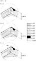
- FIG. 1 is a conceptual view showing that a limit depth when a pouch film is shaped using a conventional pouch film shaping apparatus is derived through simulation analysis.
- the conventional pouch film shaping apparatus includes a supply unit configured to supply a pouch film including a metal barrier layer and a shaping unit configured to shape the pouch film.
- the conventional pouch film shaping apparatus includes no separate preheating unit.
- FIG. 1 shows the simulation results of a forming limit using a shaping limit line calculation method proposed by Hecker.
- the case was assumed in which the initial thickness of a pouch film was set to 153 ⁇ m, the pouch film was fixed, and a shaping depth was increased using a force of about 1.5 tons until a local neck 120 was generated.
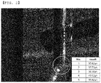
- FIG. 2 is a photograph showing a pouch film portion broken when a pouch film is shaped through the conventional pouch film shaping apparatus.
- FIG. 2 shows result values obtained by measuring the thickness of the conventional pouch film at five points, i.e. point 1 to point 5, twice.
- a metal barrier layer among a plurality of layers constituting the pouch film, is a portion that has a high possibility of damage at the time of stretching. Consequently, it is preferable that stretching force of the metal barrier layer be increased in order to reduce damage to the pouch film.
- Patent Document 1 discloses a method of separately forming a layer including a silicone-based resin and microfiber in a pouch film to increase stretching force of the entire pouch film. In this case, however, the thickness of the pouch film is increased, whereby it is difficult to obtain a high-capacity, high-density battery and it is not possible to increase stretching force of a metal barrier layer of the pouch film.
- Patent Document 2 discloses a preheating unit located ahead of a supply unit, wherein the preheating unit is formed so as to have a chamber structure and is configured to apply hot air to a raw pouch material.
- the hot air is applied to an outer coating layer of a pouch film, whereby a metal barrier layer is not heated, and therefore stretching force of the metal barrier layer is not increased.
- a hot air application time is lengthened in order to obtain sufficient stretching force, whereby the pouch film may be damaged.
- polypropylene particles applied in order to reduce surface frictional force generated on the pouch film at the time of forming the pouch film may melt. Also, even in the case in which air blowing intensity is increased in order to uniformly heat a large area, the polypropylene particles may be blown by the blown air and removed. For a pouch film having no polypropylene particles applied to the surface thereof, surface frictional force of the pouch film is increased, whereby uniform forming is not performed, and a wrinkle and bleaching phenomenon may occur at corners of an electrode assembly reception unit, and cracks may be generated in the case in which the wrinkle and bleaching phenomenon becomes serious.
- the present invention has been made in view of the above problems, and it is an object of the present invention to provide a pouch film shaping apparatus and method capable of increasing stretching force of a metal barrier layer of a pouch film using a preheating lamp configured to preheat the metal barrier layer of the pouch film, whereby it is possible to reduce damage to and defects in the pouch film.
- a pouch film shaping apparatus includes a supply unit configured to supply a pouch film including a metal barrier layer, a preheating lamp configured to preheat the metal barrier layer of the pouch film, and a shaping unit configured to shape the pouch film.
- the preheating lamp may use mid-infrared light.
- the mid-infrared light may have a wavelength range of 2 ⁇ m to 4 ⁇ m.
- the metal barrier layer may be made of aluminum.
- the preheating lamp may preheat the pouch film to 40°C to 70°C.
- a preheating region of the preheating lamp may include a pouch cup formation portion of the pouch film.
- the preheating lamp may be located before the shaping unit in an advancing direction.
- the present invention provides a pouch-shaped secondary battery including a pouch film shaped by the pouch film shaping apparatus.
- the present invention provides a battery pack including the pouch-shaped secondary battery.
- the present invention provides a pouch film shaping method including (S1) supplying a pouch film, (S2) preheating a pouch cup formation portion of the supplied pouch film, and (S3) shaping the preheated pouch cup formation portion.
- the preheating in step (S2) may be performed by a mid-infrared lamp.
- the mid-infrared lamp may use mid-infrared light having a wavelength range of 2 ⁇ m to 4 ⁇ m.
- the pouch cup formation portion may be preheated to 40°C to 70°C.
- the pouch film may include a metal barrier layer, and in step (S2), the metal barrier layer may be preheated.
- the metal barrier layer may be made of aluminum.
- one or more constructions that do not conflict with each other may be selected and combined from among the above constructions.
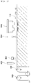
- FIG. 3 is a conceptual view of a pouch film shaping apparatus according to the present invention.
- the pouch film shaping apparatus according to the present invention includes a supply unit 200 configured to supply a pouch film 100 including a metal barrier layer, a preheating lamp 500 configured to preheat the metal barrier layer of the pouch film, and a shaping unit 600 configured to shape the pouch film.
- a cutting unit 300 configured to cut the pouch film to a desired size and a foreign matter removal unit 400 configured to suction or remove foreign matter that may be generated at the time of cutting the pouch film may be further disposed between the supply unit 200 and the preheating lamp 500.
- the cutting unit 300 and the foreign matter removal unit 400 may further be disposed behind the shaping unit 600.
- the cutting unit 300 and the foreign matter removal unit 400 are preferably located between the supply unit 200 and the preheating lamp 500.
- the foreign matter removal unit 400 may move foreign matter to a place other than the pouch film, whereby it is possible to reduce a defect rate at the time of shaping the pouch film.
- the foreign matter removal unit 400 may suction foreign matter in order to remove the foreign matter from the pouch film. The movement and the suction may be performed at once.
- a pouch film in general, includes an outer coating layer, which constitutes the outermost part thereof, a metal barrier layer configured to prevent penetration of matter, and an inner sealant layer for sealing.
- the outer coating layer serves to protect a battery from the outside, and therefore high tensile strength compared to the thickness thereof and weather resistance are required.
- the outer coating layer is mainly made of a polymer, such as oriented nylon film or PET.
- the present invention is not limited thereto.
- the metal barrier layer serves to prevent air or moisture from being introduced into the battery.
- the material for the metal barrier layer is not particularly restricted as long as the material exhibits high shapeability and ductility.
- the metal barrier layer may be made of aluminum or an aluminum alloy.
- the inner sealant layer serves to provide sealability as the result of being mutually thermally fused by heat and pressure that are applied in the state in which an electrode assembly is mounted therein, and is mainly made of cast polypropylene (CPP) film.
- An adhesive layer may be added between the outer coating layer and the metal barrier layer and/or between the metal barrier layer and the inner sealant layer. The adhesive layer serves to supplement low adhesive force between the layers located at opposite surfaces of the adhesive layer.
- the supply unit 200 serves to supply a pouch film to the pouch film shaping apparatus.
- the supply unit 200 serves to supply the pouch film so as to be easily shaped, and needs not necessarily have the form shown in FIG. 3 .
- the supply unit 200 may be configured in the form of a roll or a rail.
- the supply speed and the supply direction of the supply unit, whether to supply the pouch film from the supply unit, and the like are decided by a controller connected to the supply unit.
- the preheating lamp performs preheating in a mode in which light radiated from the lamp directly preheats the pouch film.
- the reason for this is that, in the case in which the pouch film is indirectly preheated, long time is required and efficiency is low.
- the preheating lamp 500 rapidly and accurately preheats the metal barrier layer using mid-infrared light.
- the mid-infrared light may have a wavelength range of 2 ⁇ m to 4 ⁇ m, which is a wavelength range within which aluminum in the metal barrier layer is rapidly preheated while the outer coating layer of the pouch film is not damaged.
- the pouch film is prepared so as to have a size of 200 mm x 500 mm. Subsequently, the pouch film is preheated by the preheating lamp for 4 seconds until the temperature of the pouch film reaches 40°C to 70°C such that the preheated pouch film may be shaped by the shaping unit. In the case in which the pouch film is preheated to a temperature higher than 70°C, the outer coating layer of the pouch film may be damaged or the inner sealant layer of the pouch film may melt. In the case in which the preheating temperature is lower than 40°C, the metal barrier layer of the pouch film may not be heated, whereby desired stretching force may not be obtained.
- the pouch film may be damaged.
- the metal barrier layer of the pouch film may not be heated, whereby desired stretching force may not be obtained.
- the temperature of the pouch film is not limited to the temperature range defined above as long as the components of the pouch film are not deformed or damaged.
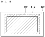
- FIG. 4 is a plan view of a pouch film showing a preheating region 510 that is preheated by the pouch film shaping apparatus according to the present invention, which shows that the preheating region 510 preheated by the preheating lamp includes a pouch cup formation portion 110 of the pouch film.
- the preheating region 510 may have an area equivalent to 100% to 120% of the area of the pouch cup formation portion 110. The reason for this is that only the region of the metal barrier layer that may be damaged due to distortion occurring at the time of pouch shaping is preheated, whereby it is possible to prevent deformation of and damage to other regions and to more easily fix the regions.
- Preheating may be performed only within a specific range, whereby the process may be simplified and time may be shortened. In addition, since light is radiated for preheating, heat may be uniformly transmitted.
- the range of the pouch cup formation portion 110 is shown as the entire region in which a cup is formed and is shown as being entirely preheated.
- the pouch film shaping apparatus according to the present invention may use a method of preheating only a region actually extended by the shaping apparatus.
- the preheating lamp 500 may be located before the shaping unit 600 in the advancing direction.
- the preheating lamp 500 may be located spaced apart from the shaping unit 600 by 20 mm to 40 cm. Since preheating is performed at a distance of 20 mm to 40 cm from the shaping unit in the advancing direction, the preheated pouch film may be directly provided to the shaping unit 600. In addition, since the pouch film is shaped in the state in which stretching force thereof is increased, breakage of the pouch film that may occur at the time of shaping may be prevented and a deeper reception unit may be formed.
- Example 1 This can be seen from the experimental results of Example 1, in which a metal barrier layer of a pouch film was preheated using mid-infrared light having a wavelength of 2 ⁇ m and then a reception unit was shaped, and Comparative Example 1, in which a reception unit was shaped without preheating a metal barrier layer of a pouch film.
- Example 1 and Comparative Example 1 pouch films, each including an outer coating layer made of PET having a thickness of 20 ⁇ m, a metal barrier layer made of aluminum having a thickness of 40 ⁇ m, and an inner sealant layer made of cast polypropylene film having a thickness of 20 ⁇ m, were tested.
- Example 1 and Comparative Example 1 the shaping unit was constituted by a die and a punch, and pressing was performed using a weight of about 1.5 tons to shape two reception units.
- FIG. 5 is a photograph showing the external appearances of pouch reception units formed by pouch film shaping apparatuses according to Comparative Example 1 and Example 1. It can be seen from FIG. 5 that, in Example 1 (b), the pouch film can be uniformly stretched using mid-infrared light, whereby a uniformly shaped reception unit is obtained, but in Comparative Example 1 (a), stretching force is low and stretching extent varies depending on regions, whereby many wrinkles are formed.
- Example 2 in which a pouch film was shaped after being heated up to 60°C using mid-infrared light having a wavelength of 2 ⁇ m
- Example 3 in which a pouch film was shaped after being heated up to 80°C using mid-infrared light having a wavelength of 2 ⁇ m, region-based aluminum residual thicknesses were measured.
- Example 2 Example 3, and Comparative Example 1, pouch films, each including an outer coating layer made of PET having a thickness of 20 ⁇ m, a metal barrier layer made of aluminum having a thickness of 40 ⁇ m, and an inner sealant layer made of cast polypropylene film having a thickness of 20 ⁇ m, were tested.
- Example 2 Example 3, and Comparative Example 1, the shaping unit was constituted by a die and a punch, and pressing was performed using a weight of about 1.5 tons to shape two reception units.
- Example 2 Example 3, and Comparative Example 1, the thicknesses of a corner portion 1 of the bottom surface of each reception unit, a side portion 2 of the reception unit, and a contact point 3 between a pouch wing and the reception unit, which are regions at which breakage mainly occurs, were measured.
- FIG. 6 is a graph showing the thicknesses of metal barrier layers of pouches formed by pouch film shaping apparatuses according to Comparative Example 1 and Examples 2 and 3. The horizontal axis of the graph indicates the respective points 1, 2, and 3, and the vertical axis of the graph indicates the thickness ( ⁇ m) of the metal barrier layer. Also, in this graph, REF indicates Comparative Example 1, 60°C indicates Example 2, and 80°C indicates Example 3.
- the thickness of the metal barrier layer is gradually reduced toward the bottom surface of the reception unit.
- Examples 2 and 3 in each of which the pouch film was preheated before shaping, have thicker metal barrier layers than Comparative Example 1. It can be seen that, in the case in which shaping is performed after preheating, the elongation of aluminum in the metal barrier layer is high, whereby breakage strength is increased, whereas in the case in which no preheating is performed before shaping, aluminum in a specific stretching portion to which great force is applied is broken, rather than being stretched.
- Example 3 is higher than the temperature in Example 2 but the aluminum residual amount in Example 2, in which shaping was performed after preheating at a temperature lower than the temperature in Example 3, is greater than the aluminum residual amount in Example 3. That is, it can be seen that, in the case in which shaping is performed at an excessively high temperature, elongation is rather excessively high, whereby the effect of preventing breakage of the pouch film is reduced. Consequently, it is preferable that only a necessary specific region of the pouch film be preheated to 40°C to 70°C.
- a pouch film shaping apparatus and method according to the present invention are capable of preheating a metal barrier layer in order to increase stretching force of a pouch film, whereby it is possible to reduce damage to and defects in the pouch film. Since the metal barrier layer is preheated to increase stretching force of the pouch film, it is possible to form a deeper reception unit than a conventional reception unit.
- a mid-infrared light irradiation unit does not occupy a large space, whereby it is possible to prevent an increase in size of the pouch film shaping apparatus.
Landscapes
- Chemical & Material Sciences (AREA)
- General Chemical & Material Sciences (AREA)
- Chemical Kinetics & Catalysis (AREA)
- Electrochemistry (AREA)
- Mechanical Engineering (AREA)
- Engineering & Computer Science (AREA)
- Physics & Mathematics (AREA)
- Electromagnetism (AREA)
- Inorganic Chemistry (AREA)
- Thermal Sciences (AREA)
- Health & Medical Sciences (AREA)
- Toxicology (AREA)
- Sealing Battery Cases Or Jackets (AREA)
- Bag Frames (AREA)
Applications Claiming Priority (2)
| Application Number | Priority Date | Filing Date | Title |
|---|---|---|---|
| KR1020190131104A KR102851596B1 (ko) | 2019-10-22 | 2019-10-22 | 이차전지용 파우치 필름 성형 장치 및 방법 |
| PCT/KR2020/014161 WO2021080255A1 (fr) | 2019-10-22 | 2020-10-16 | Appareil et procédé de formation d'un film pour étui pour une batterie secondaire |
Publications (3)
| Publication Number | Publication Date |
|---|---|
| EP4015193A1 true EP4015193A1 (fr) | 2022-06-22 |
| EP4015193A4 EP4015193A4 (fr) | 2022-11-23 |
| EP4015193B1 EP4015193B1 (fr) | 2025-12-31 |
Family
ID=75619462
Family Applications (1)
| Application Number | Title | Priority Date | Filing Date |
|---|---|---|---|
| EP20878181.5A Active EP4015193B1 (fr) | 2019-10-22 | 2020-10-16 | Appareil et procédé de formation d'un film pour étui pour une batterie secondaire |
Country Status (6)
| Country | Link |
|---|---|
| US (1) | US12592434B2 (fr) |
| EP (1) | EP4015193B1 (fr) |
| KR (1) | KR102851596B1 (fr) |
| CN (1) | CN114222657B (fr) |
| ES (1) | ES3058866T3 (fr) |
| WO (1) | WO2021080255A1 (fr) |
Families Citing this family (4)
| Publication number | Priority date | Publication date | Assignee | Title |
|---|---|---|---|---|
| KR102926461B1 (ko) * | 2021-12-23 | 2026-02-11 | 주식회사 엘지에너지솔루션 | 이차 전지용 파우치 케이스의 제조 방법 |
| KR102924506B1 (ko) * | 2021-12-23 | 2026-02-06 | 주식회사 엘지에너지솔루션 | 이차 전지용 파우치 케이스의 제조 방법 |
| KR20230119552A (ko) * | 2022-02-07 | 2023-08-16 | 주식회사 엘지에너지솔루션 | 파우치형 이차전지 실링부의 폴딩장치 및 폴딩방법 |
| EP4659934A1 (fr) | 2023-08-29 | 2025-12-10 | LG Energy Solution, Ltd. | Procédé de fabrication de batterie secondaire et appareil de fabrication de batterie secondaire |
Family Cites Families (23)
| Publication number | Priority date | Publication date | Assignee | Title |
|---|---|---|---|---|
| US4390489A (en) * | 1977-12-19 | 1983-06-28 | Allied Corporation | Method of shaping thermoplastic compositions on aluminum foil support |
| CN1280155C (zh) * | 2000-01-26 | 2006-10-18 | 大日本印刷株式会社 | 热封接方法 |
| US7927733B2 (en) | 2005-01-07 | 2011-04-19 | Lg Chem, Ltd. | Case for batteries and preparation method thereof |
| JP2006264697A (ja) * | 2005-03-22 | 2006-10-05 | Za Suzuki:Kk | 包装袋製造装置 |
| JP5573151B2 (ja) | 2009-12-25 | 2014-08-20 | 宇部興産株式会社 | 電気化学デバイス用の包装材および電気化学デバイス |
| DE202011108504U1 (de) * | 2011-11-30 | 2013-03-01 | Branson Ultraschall Niederlassung Der Emerson Technologies Gmbh & Co. Ohg | Vorrichtung zum Ultraschallschweißen |
| KR101623106B1 (ko) | 2013-05-06 | 2016-05-20 | 주식회사 엘지화학 | 파우치 필름 포밍 장치 |
| KR20150037242A (ko) | 2013-09-30 | 2015-04-08 | 주식회사 엘지화학 | 중적외선 가열기를 포함하는 전극 건조 장치 |
| JP2015123588A (ja) * | 2013-12-25 | 2015-07-06 | 日新製鋼株式会社 | 塗装金属板、塗装金属板成形物およびその製造方法 |
| KR101837234B1 (ko) | 2014-01-28 | 2018-03-09 | 주식회사 엘지화학 | 파우치 성형장치 |
| KR101587554B1 (ko) | 2015-02-23 | 2016-01-25 | (주)유진테크놀로지 | 이차전지용 파우치 성형장치 및 그 성형방법 |
| US11225348B2 (en) * | 2015-05-22 | 2022-01-18 | The Procter & Gamble Company | Process of making a water soluble pouch |
| KR101795711B1 (ko) | 2015-08-17 | 2017-11-08 | 노대수 | 배터리 셀 파우치 필름 및 그 제조방법 |
| KR101866132B1 (ko) | 2016-04-15 | 2018-07-13 | 주식회사 엘지화학 | 이차 전지용 파우치 외장재 성형 장치 및 방법 |
| JP7185995B2 (ja) | 2016-10-20 | 2022-12-08 | 凸版印刷株式会社 | 蓄電装置用外装材の製造方法及び蓄電装置の製造方法 |
| KR101866862B1 (ko) | 2016-11-29 | 2018-07-23 | 율촌화학 주식회사 | 성형성이 향상된 셀 파우치 및 이의 제조 방법 |
| KR102087992B1 (ko) * | 2017-01-11 | 2020-03-11 | 주식회사 엘지화학 | 파우치형 이차전지 및 파우치 필름 포밍 장치 |
| KR20180092174A (ko) * | 2017-02-08 | 2018-08-17 | 주식회사 엘지화학 | 이차전지의 파우치 잔존율 확보를 위한 성형 장치 및 방법 |
| AR111393A1 (es) | 2017-03-31 | 2019-07-10 | Philip Morris Products Sa | Unidad susceptora multicapas para calentar por inducción un sustrato formador de aerosol |
| KR102516223B1 (ko) | 2017-08-17 | 2023-03-30 | 주식회사 엘지에너지솔루션 | 전극 가열장치 및 그를 포함하는 이차전지용 제조시스템 |
| KR102030927B1 (ko) * | 2018-05-10 | 2019-10-10 | 경북대학교 산학협력단 | 필름 어닐링장치 |
| KR101984889B1 (ko) * | 2018-06-29 | 2019-05-31 | 디아인텍 주식회사 | 배터리 셀 파우치 필름 및 그 제조방법 |
| CN109817852A (zh) | 2018-12-29 | 2019-05-28 | 武汉依麦德新材料科技有限责任公司 | 一种锂离子电池外包装材料及其制备方法 |
-
2019
- 2019-10-22 KR KR1020190131104A patent/KR102851596B1/ko active Active
-
2020
- 2020-10-16 ES ES20878181T patent/ES3058866T3/es active Active
- 2020-10-16 EP EP20878181.5A patent/EP4015193B1/fr active Active
- 2020-10-16 CN CN202080057267.8A patent/CN114222657B/zh active Active
- 2020-10-16 US US17/763,389 patent/US12592434B2/en active Active
- 2020-10-16 WO PCT/KR2020/014161 patent/WO2021080255A1/fr not_active Ceased
Also Published As
| Publication number | Publication date |
|---|---|
| KR20210047469A (ko) | 2021-04-30 |
| KR102851596B1 (ko) | 2025-08-28 |
| WO2021080255A1 (fr) | 2021-04-29 |
| CN114222657A (zh) | 2022-03-22 |
| EP4015193A4 (fr) | 2022-11-23 |
| CN114222657B (zh) | 2024-05-03 |
| US20220367945A1 (en) | 2022-11-17 |
| EP4015193B1 (fr) | 2025-12-31 |
| ES3058866T3 (en) | 2026-03-13 |
| US12592434B2 (en) | 2026-03-31 |
Similar Documents
| Publication | Publication Date | Title |
|---|---|---|
| EP4015193B1 (fr) | Appareil et procédé de formation d'un film pour étui pour une batterie secondaire | |
| US11707880B2 (en) | Battery packaging material, production method therefor, battery, and polyester film | |
| TWI675806B (zh) | 從玻璃板形成定型玻璃物件的方法 | |
| JP6453930B2 (ja) | 積層ガラスパネルの製造 | |
| US20250319646A1 (en) | Battery packaging material, production method therefor, battery, and polyester film | |
| CN106233490B (zh) | 电池用包装材料 | |
| US11027525B2 (en) | Curved laminated glass and manufacturing method for curved laminated glass | |
| CN109560221B (zh) | 提高软包电池铝塑膜封装可靠性的方法 | |
| CN109367044B (zh) | 一种高抗冲双向拉伸聚酯/聚酰胺薄膜及其制备方法 | |
| KR102940421B1 (ko) | 파우치 필름 성형장치 및 성형방법 | |
| JP2020508282A (ja) | 減少した引張応力を有するガラスペイン | |
| CN113614888A (zh) | 保护膜及其粘贴方法以及半导体部件的制造方法 | |
| US20240360022A1 (en) | Improved edge stress using differential cooling | |
| KR101984889B1 (ko) | 배터리 셀 파우치 필름 및 그 제조방법 | |
| KR102924506B1 (ko) | 이차 전지용 파우치 케이스의 제조 방법 | |
| EP4086065B1 (fr) | Dispositif de scellage pour batterie secondaire de type sachet et procédé de fabrication de batterie secondaire de type sachet | |
| JPWO2016006191A1 (ja) | 包装材用積層体、真空断熱材用包装材及び真空断熱材 | |
| JP6969176B2 (ja) | 加飾フィルムおよびそれを用いた加飾成形体 | |
| KR20220025974A (ko) | 성형성이 향상된 나일론 필름과 이를 이용한 이차전지용 파우치 필름 | |
| US20200198315A1 (en) | Fixture for bonding purposes and method for bonding using the fixture | |
| JPH11245928A (ja) | 食品容器 | |
| JP2024544713A (ja) | 二次電池用パウチケースの製造方法 | |
| EP3786130A1 (fr) | Procédé de production de plaque de verre feuilleté légère de véhicule | |
| US20060231190A1 (en) | Method for laminating glass sheets using short wave radiation | |
| KR102671819B1 (ko) | 코팅 균일성과 장기 신뢰성이 개선된 셀 파우치용 필름 및 이의 제조 방법 |
Legal Events
| Date | Code | Title | Description |
|---|---|---|---|
| STAA | Information on the status of an ep patent application or granted ep patent |
Free format text: STATUS: THE INTERNATIONAL PUBLICATION HAS BEEN MADE |
|
| PUAI | Public reference made under article 153(3) epc to a published international application that has entered the european phase |
Free format text: ORIGINAL CODE: 0009012 |
|
| STAA | Information on the status of an ep patent application or granted ep patent |
Free format text: STATUS: REQUEST FOR EXAMINATION WAS MADE |
|
| 17P | Request for examination filed |
Effective date: 20220318 |
|
| AK | Designated contracting states |
Kind code of ref document: A1 Designated state(s): AL AT BE BG CH CY CZ DE DK EE ES FI FR GB GR HR HU IE IS IT LI LT LU LV MC MK MT NL NO PL PT RO RS SE SI SK SM TR |
|
| A4 | Supplementary search report drawn up and despatched |
Effective date: 20221025 |
|
| RIC1 | Information provided on ipc code assigned before grant |
Ipc: B29C 35/08 20060101ALN20221019BHEP Ipc: B29C 35/02 20060101ALN20221019BHEP Ipc: B29L 31/34 20060101ALN20221019BHEP Ipc: B29C 51/42 20060101ALI20221019BHEP Ipc: B29C 51/14 20060101ALI20221019BHEP Ipc: B29C 51/08 20060101ALI20221019BHEP Ipc: B29C 51/02 20060101ALI20221019BHEP Ipc: B29C 65/34 20060101ALI20221019BHEP Ipc: H01M 50/105 20210101ALI20221019BHEP Ipc: B29L 31/00 20060101ALI20221019BHEP Ipc: B29C 65/14 20060101ALI20221019BHEP Ipc: B29C 65/02 20060101ALI20221019BHEP Ipc: B29C 65/00 20060101ALI20221019BHEP Ipc: B29C 65/70 20060101ALI20221019BHEP Ipc: H01M 50/10 20210101ALI20221019BHEP Ipc: B29C 59/00 20060101ALI20221019BHEP Ipc: B29C 59/02 20060101AFI20221019BHEP |
|
| DAV | Request for validation of the european patent (deleted) | ||
| DAX | Request for extension of the european patent (deleted) | ||
| STAA | Information on the status of an ep patent application or granted ep patent |
Free format text: STATUS: EXAMINATION IS IN PROGRESS |
|
| 17Q | First examination report despatched |
Effective date: 20240830 |
|
| GRAP | Despatch of communication of intention to grant a patent |
Free format text: ORIGINAL CODE: EPIDOSNIGR1 |
|
| STAA | Information on the status of an ep patent application or granted ep patent |
Free format text: STATUS: GRANT OF PATENT IS INTENDED |
|
| RIC1 | Information provided on ipc code assigned before grant |
Ipc: B29C 59/02 20060101AFI20250825BHEP Ipc: B29C 59/00 20060101ALI20250825BHEP Ipc: H01M 50/10 20210101ALI20250825BHEP Ipc: B29C 65/70 20060101ALI20250825BHEP Ipc: B29C 65/00 20060101ALI20250825BHEP Ipc: B29C 65/02 20060101ALI20250825BHEP Ipc: B29C 65/14 20060101ALI20250825BHEP Ipc: B29L 31/00 20060101ALI20250825BHEP Ipc: H01M 50/105 20210101ALI20250825BHEP Ipc: B29C 65/34 20060101ALI20250825BHEP Ipc: B29C 51/02 20060101ALI20250825BHEP Ipc: B29C 51/08 20060101ALI20250825BHEP Ipc: B29C 51/14 20060101ALI20250825BHEP Ipc: B29C 51/42 20060101ALI20250825BHEP Ipc: H01M 50/119 20210101ALI20250825BHEP Ipc: H01M 50/121 20210101ALI20250825BHEP Ipc: H01M 50/124 20210101ALI20250825BHEP Ipc: H01M 50/211 20210101ALI20250825BHEP Ipc: B29L 31/34 20060101ALN20250825BHEP Ipc: B29C 35/02 20060101ALN20250825BHEP Ipc: B29C 35/08 20060101ALN20250825BHEP |
|
| INTG | Intention to grant announced |
Effective date: 20250918 |
|
| P01 | Opt-out of the competence of the unified patent court (upc) registered |
Free format text: CASE NUMBER: UPC_APP_8716_4015193/2025 Effective date: 20251002 |
|
| GRAS | Grant fee paid |
Free format text: ORIGINAL CODE: EPIDOSNIGR3 |
|
| GRAA | (expected) grant |
Free format text: ORIGINAL CODE: 0009210 |
|
| STAA | Information on the status of an ep patent application or granted ep patent |
Free format text: STATUS: THE PATENT HAS BEEN GRANTED |
|
| AK | Designated contracting states |
Kind code of ref document: B1 Designated state(s): AL AT BE BG CH CY CZ DE DK EE ES FI FR GB GR HR HU IE IS IT LI LT LU LV MC MK MT NL NO PL PT RO RS SE SI SK SM TR |
|
| REG | Reference to a national code |
Ref country code: CH Ref legal event code: F10 Free format text: ST27 STATUS EVENT CODE: U-0-0-F10-F00 (AS PROVIDED BY THE NATIONAL OFFICE) Effective date: 20251231 Ref country code: GB Ref legal event code: FG4D |
|
| REG | Reference to a national code |
Ref country code: DE Ref legal event code: R096 Ref document number: 602020064927 Country of ref document: DE |
|
| REG | Reference to a national code |
Ref country code: IE Ref legal event code: FG4D |
|
| REG | Reference to a national code |
Ref country code: ES Ref legal event code: FG2A Ref document number: 3058866 Country of ref document: ES Kind code of ref document: T3 Effective date: 20260313 |
|
| REG | Reference to a national code |
Ref country code: LT Ref legal event code: MG9D |
|
| PG25 | Lapsed in a contracting state [announced via postgrant information from national office to epo] |
Ref country code: NO Free format text: LAPSE BECAUSE OF FAILURE TO SUBMIT A TRANSLATION OF THE DESCRIPTION OR TO PAY THE FEE WITHIN THE PRESCRIBED TIME-LIMIT Effective date: 20260331 |
|
| PG25 | Lapsed in a contracting state [announced via postgrant information from national office to epo] |
Ref country code: HR Free format text: LAPSE BECAUSE OF FAILURE TO SUBMIT A TRANSLATION OF THE DESCRIPTION OR TO PAY THE FEE WITHIN THE PRESCRIBED TIME-LIMIT Effective date: 20251231 Ref country code: FI Free format text: LAPSE BECAUSE OF FAILURE TO SUBMIT A TRANSLATION OF THE DESCRIPTION OR TO PAY THE FEE WITHIN THE PRESCRIBED TIME-LIMIT Effective date: 20251231 |
|
| PG25 | Lapsed in a contracting state [announced via postgrant information from national office to epo] |
Ref country code: RS Free format text: LAPSE BECAUSE OF FAILURE TO SUBMIT A TRANSLATION OF THE DESCRIPTION OR TO PAY THE FEE WITHIN THE PRESCRIBED TIME-LIMIT Effective date: 20260331 |
|
| PG25 | Lapsed in a contracting state [announced via postgrant information from national office to epo] |
Ref country code: LV Free format text: LAPSE BECAUSE OF FAILURE TO SUBMIT A TRANSLATION OF THE DESCRIPTION OR TO PAY THE FEE WITHIN THE PRESCRIBED TIME-LIMIT Effective date: 20251231 |