EP4015263B1 - Kraftfahrzeug - Google Patents
Kraftfahrzeug Download PDFInfo
- Publication number
- EP4015263B1 EP4015263B1 EP21215657.4A EP21215657A EP4015263B1 EP 4015263 B1 EP4015263 B1 EP 4015263B1 EP 21215657 A EP21215657 A EP 21215657A EP 4015263 B1 EP4015263 B1 EP 4015263B1
- Authority
- EP
- European Patent Office
- Prior art keywords
- structural element
- lateral
- axially
- filtration
- motor vehicle
- Prior art date
- Legal status (The legal status is an assumption and is not a legal conclusion. Google has not performed a legal analysis and makes no representation as to the accuracy of the status listed.)
- Active
Links
Images




Classifications
-
- B—PERFORMING OPERATIONS; TRANSPORTING
- B60—VEHICLES IN GENERAL
- B60G—VEHICLE SUSPENSION ARRANGEMENTS
- B60G15/00—Resilient suspensions characterised by arrangement, location or type of combined spring and vibration damper, e.g. telescopic type
- B60G15/02—Resilient suspensions characterised by arrangement, location or type of combined spring and vibration damper, e.g. telescopic type having mechanical spring
- B60G15/06—Resilient suspensions characterised by arrangement, location or type of combined spring and vibration damper, e.g. telescopic type having mechanical spring and fluid damper
- B60G15/067—Resilient suspensions characterised by arrangement, location or type of combined spring and vibration damper, e.g. telescopic type having mechanical spring and fluid damper characterised by the mounting on the vehicle body or chassis of the spring and damper unit
- B60G15/068—Resilient suspensions characterised by arrangement, location or type of combined spring and vibration damper, e.g. telescopic type having mechanical spring and fluid damper characterised by the mounting on the vehicle body or chassis of the spring and damper unit specially adapted for MacPherson strut-type suspension
-
- F—MECHANICAL ENGINEERING; LIGHTING; HEATING; WEAPONS; BLASTING
- F16—ENGINEERING ELEMENTS AND UNITS; GENERAL MEASURES FOR PRODUCING AND MAINTAINING EFFECTIVE FUNCTIONING OF MACHINES OR INSTALLATIONS; THERMAL INSULATION IN GENERAL
- F16C—SHAFTS; FLEXIBLE SHAFTS; ELEMENTS OR CRANKSHAFT MECHANISMS; ROTARY BODIES OTHER THAN GEARING ELEMENTS; BEARINGS
- F16C17/00—Sliding-contact bearings for exclusively rotary movement
- F16C17/04—Sliding-contact bearings for exclusively rotary movement for axial load only
-
- F—MECHANICAL ENGINEERING; LIGHTING; HEATING; WEAPONS; BLASTING
- F16—ENGINEERING ELEMENTS AND UNITS; GENERAL MEASURES FOR PRODUCING AND MAINTAINING EFFECTIVE FUNCTIONING OF MACHINES OR INSTALLATIONS; THERMAL INSULATION IN GENERAL
- F16C—SHAFTS; FLEXIBLE SHAFTS; ELEMENTS OR CRANKSHAFT MECHANISMS; ROTARY BODIES OTHER THAN GEARING ELEMENTS; BEARINGS
- F16C19/00—Bearings with rolling contact, for exclusively rotary movement
- F16C19/02—Bearings with rolling contact, for exclusively rotary movement with bearing balls essentially of the same size in one or more circular rows
- F16C19/10—Bearings with rolling contact, for exclusively rotary movement with bearing balls essentially of the same size in one or more circular rows for axial load mainly
- F16C19/12—Bearings with rolling contact, for exclusively rotary movement with bearing balls essentially of the same size in one or more circular rows for axial load mainly for supporting the end face of a shaft or other member, e.g. footstep bearings
-
- F—MECHANICAL ENGINEERING; LIGHTING; HEATING; WEAPONS; BLASTING
- F16—ENGINEERING ELEMENTS AND UNITS; GENERAL MEASURES FOR PRODUCING AND MAINTAINING EFFECTIVE FUNCTIONING OF MACHINES OR INSTALLATIONS; THERMAL INSULATION IN GENERAL
- F16C—SHAFTS; FLEXIBLE SHAFTS; ELEMENTS OR CRANKSHAFT MECHANISMS; ROTARY BODIES OTHER THAN GEARING ELEMENTS; BEARINGS
- F16C27/00—Elastic or yielding bearings or bearing supports, for exclusively rotary movement
- F16C27/06—Elastic or yielding bearings or bearing supports, for exclusively rotary movement by means of parts of rubber or like materials
- F16C27/066—Ball or roller bearings
-
- F—MECHANICAL ENGINEERING; LIGHTING; HEATING; WEAPONS; BLASTING
- F16—ENGINEERING ELEMENTS AND UNITS; GENERAL MEASURES FOR PRODUCING AND MAINTAINING EFFECTIVE FUNCTIONING OF MACHINES OR INSTALLATIONS; THERMAL INSULATION IN GENERAL
- F16C—SHAFTS; FLEXIBLE SHAFTS; ELEMENTS OR CRANKSHAFT MECHANISMS; ROTARY BODIES OTHER THAN GEARING ELEMENTS; BEARINGS
- F16C33/00—Parts of bearings; Special methods for making bearings or parts thereof
- F16C33/72—Sealings
- F16C33/76—Sealings of ball or roller bearings
- F16C33/761—Sealings of ball or roller bearings specifically for bearings with purely axial load
-
- B—PERFORMING OPERATIONS; TRANSPORTING
- B60—VEHICLES IN GENERAL
- B60G—VEHICLE SUSPENSION ARRANGEMENTS
- B60G2204/00—Indexing codes related to suspensions per se or to auxiliary parts
- B60G2204/10—Mounting of suspension elements
- B60G2204/12—Mounting of springs or dampers
- B60G2204/128—Damper mount on vehicle body or chassis
-
- B—PERFORMING OPERATIONS; TRANSPORTING
- B60—VEHICLES IN GENERAL
- B60G—VEHICLE SUSPENSION ARRANGEMENTS
- B60G2204/00—Indexing codes related to suspensions per se or to auxiliary parts
- B60G2204/40—Auxiliary suspension parts; Adjustment of suspensions
- B60G2204/418—Bearings, e.g. ball or roller bearings
-
- F—MECHANICAL ENGINEERING; LIGHTING; HEATING; WEAPONS; BLASTING
- F16—ENGINEERING ELEMENTS AND UNITS; GENERAL MEASURES FOR PRODUCING AND MAINTAINING EFFECTIVE FUNCTIONING OF MACHINES OR INSTALLATIONS; THERMAL INSULATION IN GENERAL
- F16C—SHAFTS; FLEXIBLE SHAFTS; ELEMENTS OR CRANKSHAFT MECHANISMS; ROTARY BODIES OTHER THAN GEARING ELEMENTS; BEARINGS
- F16C2326/00—Articles relating to transporting
- F16C2326/01—Parts of vehicles in general
- F16C2326/05—Vehicle suspensions, e.g. bearings, pivots or connecting rods used therein
-
- F—MECHANICAL ENGINEERING; LIGHTING; HEATING; WEAPONS; BLASTING
- F16—ENGINEERING ELEMENTS AND UNITS; GENERAL MEASURES FOR PRODUCING AND MAINTAINING EFFECTIVE FUNCTIONING OF MACHINES OR INSTALLATIONS; THERMAL INSULATION IN GENERAL
- F16F—SPRINGS; SHOCK-ABSORBERS; MEANS FOR DAMPING VIBRATION
- F16F9/00—Springs, vibration-dampers, shock-absorbers, or similarly-constructed movement-dampers using a fluid or the equivalent as damping medium
- F16F9/32—Details
- F16F9/54—Arrangements for attachment
-
- F—MECHANICAL ENGINEERING; LIGHTING; HEATING; WEAPONS; BLASTING
- F16—ENGINEERING ELEMENTS AND UNITS; GENERAL MEASURES FOR PRODUCING AND MAINTAINING EFFECTIVE FUNCTIONING OF MACHINES OR INSTALLATIONS; THERMAL INSULATION IN GENERAL
- F16F—SPRINGS; SHOCK-ABSORBERS; MEANS FOR DAMPING VIBRATION
- F16F9/00—Springs, vibration-dampers, shock-absorbers, or similarly-constructed movement-dampers using a fluid or the equivalent as damping medium
- F16F9/32—Details
- F16F9/58—Stroke limiting stops, e.g. arranged on the piston rod outside the cylinder
Definitions
- the present invention relates to a vehicle.
- the invention aims to propose an integrated and compact design of the different components of the upper part of such a strut which in particular facilitates assembly, assembly, and maintenance.
- the vertical direction is used as a purely geometric reference as being a direction orthogonal to the road on which the vehicle is located.
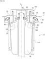
- the strut 12 comprises a shock absorber 14 of axis “A” comprising a body 16 in which a rod 18 is mounted telescopically axially along the axis A.
- a lower end of the body 16 is linked with an associated steering wheel 20 of the vehicle, for example via a yoke (not shown), while the free upper end section 19 of the rod 18 is intended to be linked to a suspended structural element 22 of the vehicle, such as a bodywork element or a bodywork element, or any component attached and fixed to such an element.
- a suspended structural element 22 of the vehicle such as a bodywork element or a bodywork element, or any component attached and fixed to such an element.
- the spring 24 is threaded around the shock absorber rod 18 and these two elements are generally coaxial.
- the upper cup 28 is linked to the structural element 22 via a rotating stop 30 which is here represented in the form of a stop ball, or alternatively a stop comprising a friction ring.
- the filtration assembly 36 is subjected only to the forces passing through the telescopic rod 18 of the shock absorber 16. The filtration assembly 36 does not receive any force coming from the helical spring 24.
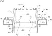
- the annular lower radial partition 76 is centrally pierced by a hole 78 for the passage of the upper end section 19 of the telescopic rod 18.
- the annular lower radial partition 76 is presented as an intermediate partition which divides the internal cavity of the multifunction support 60 in two to axially delimit the two upper filtration cavities 66 and lower shock 68.
- the lower cylindrical barrel 80 has a rib 82 which cooperates with a groove 39 facing the shock block 38.
- the lateral flange 72 for mounting the multifunction support 60 on the structural element 22 extends radially outwards from the external side wall of the multifunction support 60.
- the annular lateral flange 72 comprises a radially inner annular fixing cheek 84 which is extended by a radially outer lateral flange 86 of tubular shape which laterally surrounds the rotating stop 30.
- the washer has circularly positioned openings on the upper surface.
- the openings are in the form of slots regularly distributed circularly, and through which the hooks 92 of the upper end of the filtration barrel 74 pass. Each hook 92 passes through the slot opposite the washer 94.
- Each clamping screw 101 is mounted screwed into a tapped hole 99 of the side mounting flange 72 of the multifunction support 60 and whose clamping head is capable of cooperating with the opposite portion 23 of the structural element 22 for the tighten axially against a portion facing the upper face 87 the side mounting flange 72.
- the hydraulic shock absorber transmits its force to the structural element 22, 23 via the rod 18, the filter block 36, the multifunction support 60 and the nut 100.
- the rotating stop 30 is a ball stop which surrounds the filtration cavity which houses the filter block 36.
- the multifunction support 60 does not include an internal radial partition which delimits between them the upper filtration cavities 66 and lower 68 shock cavities.
- the multifunction support 60 is internally stepped and its lower section 80 of larger diameter delimits the impact cavity 68.
Landscapes
- Engineering & Computer Science (AREA)
- General Engineering & Computer Science (AREA)
- Mechanical Engineering (AREA)
- Vehicle Body Suspensions (AREA)
- Fluid-Damping Devices (AREA)
Claims (9)
- Kraftfahrzeug, welches ein Federbein (12) und ein Strukturelement (22) umfasst, wobei das Federbein (12) dazu bestimmt ist, an einer Aufhängung eines Rades (20) des Fahrzeugs eingesetzt zu werden, wobei das Federbein (12) aufweist:- einen Stoßdämpfer (16), der mit einer axialen Teleskopstange (18) ausgestattet ist, von der ein oberer Endabschnitt (19) mit dem Strukturelement (22) des Kraftfahrzeugs verbunden ist;- eine Schraubenfeder (24), welche die Teleskopstange (18) umgibt;- einen oberen Federteller (28) zur axialen Abstützung des oberen Endes der Schraubenfeder (24);- einen Drehanschlag (30), der axial zwischen dem oberen Federteller (28) und dem Strukturelement (22) angeordnet ist und der einen oberen Ring (31), der bezüglich des Strukturelements (22) ortsfest ist, und einen drehbaren unteren Ring (29), der die Kraft der Schraubenfeder (24) aufnimmt, aufweist;- einen Stoßblock (38), der die Teleskopstange (18) umgibt und von dem ein oberer Abschnitt (37) seine Kraft auf das Strukturelement (22) überträgt;- eine Filteranordnung (36), welche eine radial äußere zylindrische Hülle (40), die an dem Strukturelement (22) befestigt ist, einen dazwischenliegend angeordneten Filterblock (42) und ein radial inneres Befestigungselement (44, 46), an dem der obere Endabschnitt (19) der Teleskopstange (18) befestigt ist, aufweist, wobei das Federbein dadurch definiert ist, dass es einen einstückigen Multifunktionsträger (60) aufweist, welcher aufweist:- einen axial nach oben offenen Filtrationshohlraum (66), in dem die äußere Hülle (40) der Filteranordnung (36) befestigt ist;- einen axial nach unten offenen Stoßhohlraum (68), in dem der obere Abschnitt des Stoßblocks angebracht ist;- eine seitliche Aufnahme (70), in welcher der Drehanschlag (30) angebracht ist;- und einen seitlichen Flansch (72) zur Montage des Multifunktionsträgers (60) an dem Strukturelement (22), und wobei das Federbein dadurch definiert ist, dass es aufweist:- ein oberes Element (94), das eine Vorspannkraft auf den Filterblock (42, 98) ausübt;- mindestens ein Element (100) zur Befestigung des Multifunktionsträgers (60) an dem Strukturelement (22) durch axiales Verspannen seines seitlichen Montageflansches (102) mit einem gegenüberliegenden Abschnitt (23) des Strukturelements (22), und dadurch, dass der Multifunktionsträger (60) aufweist:- eine axial nach oben offene zylindrische Filtrationshülse (74), die aus einem seitlichen zylindrischen Mantel (74) besteht, der den Filtrationshohlraum (66) seitlich begrenzt, und dadurch, dass das obere Element eine runde Scheibe (94) ist, die durch elastisches Aufstecken auf das obere Ende (92) der Filtrationshülse (74) befestigt ist und von der eine Unterseite (96) eine Vorspannkraft auf den Filterblock (42, 98) ausübt,dadurch gekennzeichnet, dass ein oberes Ende der Filtrationshülse (74) mit Haken (92) versehen ist, wobei die runde Scheibe (94) eine Oberseite aufweist, die mit Öffnungen versehen ist, die von den Haken (92) des oberen Endes der Filtrationshülse (74) in der auf dem Multifunktionsträger (60) montierten Position der runden Scheibe (94) durchquert werden,wobei das Federbein (12) außerdem dadurch definiert ist, dass in der auf dem Multifunktionsträger (60) montierten Position der runden Scheibe (94) die ringförmige Unterseite (96) der runden Scheibe (94) eine bestimmte Vorspannkraft auf den Filterblock (42) ausübt, wodurch der Wert der auf den Filterblock ausgeübten Vorspannkraft geändert werden kann, indem die Abmessungen der oberen runden Scheibe (94) geändert werden, wobei das mindestens eine Element zur Befestigung des Multifunktionsträgers (60) an dem Strukturelement (22) eine Mutter (100) zum axialen Festspannen ist, die durch Aufschrauben auf einen mit einem Außengewinde versehenen Abschnitt (73) der zylindrischen Befestigungshülse (74) angebracht ist, und dadurch, dass der Wert der Vorspannkraft, die von der runden Scheibe (94) auf den Filterblock ausgeübt wird, unabhängig von der Spannposition der Mutter (100) ist.
- Kraftfahrzeug nach Anspruch 1, dadurch gekennzeichnet, dass der Multifunktionsträger (60) aufweist:- eine axial nach oben offene zylindrische Filtrationshülse (74), die aus einem seitlichen zylindrischen Mantel (74) und einer unteren radialen Trennwand (76) besteht, die den Filtrationshohlraum (66) seitlich und axial nach unten begrenzen, und deren untere radiale Trennwand (76) für den Durchgang des oberen Endabschnitts (19) der Teleskopstange (18) mittig durchbohrt (78) ist;
eine axial nach unten offene zylindrische Stoßhülse (68), die aus einem seitlichen zylindrischen Mantel (68) und der radialen Trennwand (76) besteht, die den Stoßhohlraum (68) seitlich und axial nach oben begrenzen;- den seitlichen Flansch (72) zur Montage des Multifunktionsträgers (60) an dem Strukturelement (22), der sich radial nach außen erstreckt, von dem eine Unterseite (88) die seitliche Aufnahme (70) axial nach oben begrenzt und gegenüber von dem der obere Ring (31) des Drehanschlags (30) angeordnet ist;- ein komplementäres ringförmiges Teil (29, 104), das unter dem seitlichen Montageflansch (72) angebracht ist und das mit dem seitlichen Montageflansch (72) die seitliche Aufnahme (70) begrenzt. - Kraftfahrzeug nach einem der vorhergehenden Ansprüche, dadurch gekennzeichnet, dass der Drehanschlag (30) axial unterhalb des Filtrationshohlraums (66) angeordnet ist.
- Kraftfahrzeug nach einem der Ansprüche 1 und 2, dadurch gekennzeichnet, dass der Drehanschlag (30) den Filtrationshohlraum (66) umgibt.
- Kraftfahrzeug nach einem der vorhergehenden Ansprüche, dadurch gekennzeichnet, dass der Stoßhohlraum (68) Mittel (82) zum Anhängen des oberen Abschnitts (37) des Stoßblocks (38) aufweist.
- Kraftfahrzeug nach Anspruch 1, dadurch gekennzeichnet, dass die Mutter (100) zum axialen Festspannen, die durch Aufschrauben auf einen mit einem Außengewinde versehenen Abschnitt (73) der zylindrischen Befestigungshülse (74) angebracht ist, einen unteren seitlichen Spannkragen (102) aufweist, der geeignet ist, mit einem gegenüberliegenden Abschnitt (84) des seitlichen Flansches (72) zur Montage des Multifunktionsträgers (60) zusammenzuwirken, um einen Abschnitt (23) des Strukturelements (22) mit einem gegenüberliegenden Abschnitt des seitlichen Montageflansches (72) axial zu verspannen.
- Kraftfahrzeug nach Anspruch 1, dadurch gekennzeichnet, dass die radial äußere zylindrische Hülle (40) der Filteranordnung (36) eine Buchse ist, die durch axiales Einpressen im Inneren der Filtrationshülse (74) des Multifunktionsträgers (60) angebracht ist.
- Kraftfahrzeug nach Anspruch 1, dadurch gekennzeichnet, dass der Drehanschlag (30) ein Druckkugellager ist, das in der seitlichen Aufnahme (70) zwischen dem seitlichen Flansch (72) und dem komplementären ringförmigen Teil (104), das unter dem seitlichen Flansch (72) angebracht ist, aufgenommen ist.
- Kraftfahrzeug nach Anspruch 1, dadurch gekennzeichnet, dass der Drehanschlag (30) ein Reibring-Anschlag (32) ist, der axial zwischen dem oberen Ring (31) des Drehanschlags (30) angeordnet ist, der unter dem seitlichen Montageflansch (72) befestigt ist, und dadurch, dass das komplementäre ringförmige Teil, das unter dem seitlichen Montageflansch (72) angebracht ist, den drehbaren unteren Ring (29) des Drehanschlags (30) bildet.
Applications Claiming Priority (1)
| Application Number | Priority Date | Filing Date | Title |
|---|---|---|---|
| FR2013602A FR3117943B3 (fr) | 2020-12-18 | 2020-12-18 | Jambe de force de suspension de vehicule automobile |
Publications (2)
| Publication Number | Publication Date |
|---|---|
| EP4015263A1 EP4015263A1 (de) | 2022-06-22 |
| EP4015263B1 true EP4015263B1 (de) | 2024-07-10 |
Family
ID=74347444
Family Applications (1)
| Application Number | Title | Priority Date | Filing Date |
|---|---|---|---|
| EP21215657.4A Active EP4015263B1 (de) | 2020-12-18 | 2021-12-17 | Kraftfahrzeug |
Country Status (2)
| Country | Link |
|---|---|
| EP (1) | EP4015263B1 (de) |
| FR (1) | FR3117943B3 (de) |
Families Citing this family (2)
| Publication number | Priority date | Publication date | Assignee | Title |
|---|---|---|---|---|
| FR3137610B1 (fr) * | 2022-07-07 | 2024-06-28 | Ntn Snr Roulements | Sous-ensemble filtrant pour un Assemblage de butée SUPÉRIEURE d’une jambe de suspension de véhicule automobile, assemblage, jambe de suspension et procédé d’assemblage associés |
| US11872859B1 (en) * | 2022-08-03 | 2024-01-16 | GM Global Technology Operations LLC | Top mount hydraulic bump stop |
Family Cites Families (11)
| Publication number | Priority date | Publication date | Assignee | Title |
|---|---|---|---|---|
| JP4378983B2 (ja) * | 2003-03-25 | 2009-12-09 | オイレス工業株式会社 | ストラット滑り軸受 |
| DE10335956A1 (de) * | 2003-08-04 | 2005-02-24 | Basf Ag | Federkonstruktion |
| DE102007023886A1 (de) * | 2007-05-23 | 2008-12-11 | Woco Avs Gmbh | Einsatzlagerteil, elastisches Einsatzlager und Federbeinlageranordnung |
| US8931768B2 (en) * | 2012-06-12 | 2015-01-13 | GM Global Technology Operations LLC | Mount assembly for suspension damper |
| DE102014218800A1 (de) * | 2014-09-18 | 2016-03-24 | Bayerische Motoren Werke Aktiengesellschaft | Dämpferanordnung eines Fahrzeuges |
| DE102016214179B4 (de) * | 2016-08-01 | 2021-11-18 | Bayerische Motoren Werke Aktiengesellschaft | Stützlager eines Schwingungsdämpfers in der Radaufhängung eines Fahrzeugs |
| DE102017205091A1 (de) * | 2017-03-27 | 2018-09-27 | Bayerische Motoren Werke Aktiengesellschaft | Stützlager eines Schwingungsdämpfers in der Radaufhängung eines Fahrzeugs |
| DE102017009601A1 (de) * | 2017-10-16 | 2018-05-09 | Daimler Ag | Dämperbein für ein Fahrzeug |
| DE102017009600A1 (de) * | 2017-10-16 | 2018-05-09 | Daimler Ag | Dämpferbein für ein Fahrzeug |
| DE102017221651A1 (de) * | 2017-12-01 | 2019-06-06 | Volkswagen Aktiengesellschaft | Dämpferlager |
| DE202019106036U1 (de) * | 2019-10-30 | 2019-12-02 | Vibracoustic Ag | Lagerstrukturbauteil |
-
2020
- 2020-12-18 FR FR2013602A patent/FR3117943B3/fr active Active
-
2021
- 2021-12-17 EP EP21215657.4A patent/EP4015263B1/de active Active
Also Published As
| Publication number | Publication date |
|---|---|
| FR3117943A3 (fr) | 2022-06-24 |
| FR3117943B3 (fr) | 2022-12-23 |
| EP4015263A1 (de) | 2022-06-22 |
Similar Documents
| Publication | Publication Date | Title |
|---|---|---|
| EP0126006B1 (de) | Verbindungsvorrichtung zwischen dem Aufbau eines Fahrzeuges und einem Aufhängungsbein | |
| EP4015262A1 (de) | Federbein einer fahrzeugaufhängung | |
| FR2936580A1 (fr) | Butee de suspension et jambe de force associee | |
| EP1243446B1 (de) | Axialwälzlager für eine Fahrzeugaufhängung mit Rückhaltemittel | |
| FR2461147A1 (fr) | Coussinet composite pour articulation a rotule | |
| EP4015263A1 (de) | Federbein der aufhängung eines kraftfahrzeugs | |
| EP2904889B1 (de) | Rad, das ein verbessertes landwirtschaftliches gerät bildet | |
| WO2020016347A1 (fr) | Butée de suspension de véhicule automobile | |
| FR2654406A1 (fr) | Fourche avant de motocyclette. | |
| FR3052433A1 (fr) | Systeme de suspension arriere pour velo | |
| EP1029719B1 (de) | Obere Federbeinsbefestigung für eine MacPherson-Typ-Aufhängung, und Aufhängung mit einer solchen Befestigung | |
| FR2839471A1 (fr) | Butee de suspension pour roue motrice de vehicule automobile | |
| EP1378682A1 (de) | Hydroelastisches axialwirkendes Gelenk | |
| FR2768659A1 (fr) | Dispositif de suspension de roue de vehicule | |
| EP0292371B1 (de) | Radsatz für lenkbare Räder eines Kraftfahrzeuges mit teleskopischen Federbeinen mit Schrägfedern | |
| FR3121210A1 (fr) | Ensemble comportant un support et un capteur de la vitesse de rotation d’une roue de vehicule automobile | |
| EP4313651B1 (de) | Auspuffstrangaufhängung eines fahrzeugs | |
| FR2789134A1 (fr) | Ensemble pour le calage d'un roulement a contact oblique sur un arbre, module de roulement et agencement de l'arbre dans un support au moyen de l'ensemble de calage | |
| EP3098149B1 (de) | Fahrradrahmen | |
| FR2783203A1 (fr) | Dispositif d'appui superieur d'un amortisseur de suspension avant d'un vehicule automobile | |
| EP1892130A1 (de) | Vorrichtung zur obenseitigen Befestigung eines Stossdämpfers an der Karosserie eines Fahrzeugs | |
| EP3828434B1 (de) | Federbeinanordnung eines kraftfahrzeuges | |
| EP3385152B1 (de) | Fahrradgabel und gabelschaft und gabelkopf, aus dem diese besteht | |
| EP0343035B1 (de) | Winkelreguliereinrichtung eines Rades auf der Lenksäule eines Kraftfahrzeuges | |
| FR2827551A3 (fr) | Element d'assemblage superieur pour ressort pneumatique de vehicule automobile |
Legal Events
| Date | Code | Title | Description |
|---|---|---|---|
| PUAI | Public reference made under article 153(3) epc to a published international application that has entered the european phase |
Free format text: ORIGINAL CODE: 0009012 |
|
| STAA | Information on the status of an ep patent application or granted ep patent |
Free format text: STATUS: THE APPLICATION HAS BEEN PUBLISHED |
|
| AK | Designated contracting states |
Kind code of ref document: A1 Designated state(s): AL AT BE BG CH CY CZ DE DK EE ES FI FR GB GR HR HU IE IS IT LI LT LU LV MC MK MT NL NO PL PT RO RS SE SI SK SM TR |
|
| RAP3 | Party data changed (applicant data changed or rights of an application transferred) |
Owner name: RENAULT S.A.S |
|
| STAA | Information on the status of an ep patent application or granted ep patent |
Free format text: STATUS: REQUEST FOR EXAMINATION WAS MADE |
|
| 17P | Request for examination filed |
Effective date: 20221221 |
|
| RBV | Designated contracting states (corrected) |
Designated state(s): AL AT BE BG CH CY CZ DE DK EE ES FI FR GB GR HR HU IE IS IT LI LT LU LV MC MK MT NL NO PL PT RO RS SE SI SK SM TR |
|
| STAA | Information on the status of an ep patent application or granted ep patent |
Free format text: STATUS: EXAMINATION IS IN PROGRESS |
|
| 17Q | First examination report despatched |
Effective date: 20230614 |
|
| P01 | Opt-out of the competence of the unified patent court (upc) registered |
Effective date: 20230608 |
|
| GRAP | Despatch of communication of intention to grant a patent |
Free format text: ORIGINAL CODE: EPIDOSNIGR1 |
|
| STAA | Information on the status of an ep patent application or granted ep patent |
Free format text: STATUS: GRANT OF PATENT IS INTENDED |
|
| INTG | Intention to grant announced |
Effective date: 20240206 |
|
| GRAS | Grant fee paid |
Free format text: ORIGINAL CODE: EPIDOSNIGR3 |
|
| GRAA | (expected) grant |
Free format text: ORIGINAL CODE: 0009210 |
|
| STAA | Information on the status of an ep patent application or granted ep patent |
Free format text: STATUS: THE PATENT HAS BEEN GRANTED |
|
| AK | Designated contracting states |
Kind code of ref document: B1 Designated state(s): AL AT BE BG CH CY CZ DE DK EE ES FI FR GB GR HR HU IE IS IT LI LT LU LV MC MK MT NL NO PL PT RO RS SE SI SK SM TR |
|
| REG | Reference to a national code |
Ref country code: CH Ref legal event code: EP |
|
| REG | Reference to a national code |
Ref country code: DE Ref legal event code: R096 Ref document number: 602021015429 Country of ref document: DE |
|
| REG | Reference to a national code |
Ref country code: LT Ref legal event code: MG9D |
|
| REG | Reference to a national code |
Ref country code: NL Ref legal event code: MP Effective date: 20240710 |
|
| PG25 | Lapsed in a contracting state [announced via postgrant information from national office to epo] |
Ref country code: PT Free format text: LAPSE BECAUSE OF FAILURE TO SUBMIT A TRANSLATION OF THE DESCRIPTION OR TO PAY THE FEE WITHIN THE PRESCRIBED TIME-LIMIT Effective date: 20241111 |
|
| REG | Reference to a national code |
Ref country code: AT Ref legal event code: MK05 Ref document number: 1701753 Country of ref document: AT Kind code of ref document: T Effective date: 20240710 |
|
| PG25 | Lapsed in a contracting state [announced via postgrant information from national office to epo] |
Ref country code: NL Free format text: LAPSE BECAUSE OF FAILURE TO SUBMIT A TRANSLATION OF THE DESCRIPTION OR TO PAY THE FEE WITHIN THE PRESCRIBED TIME-LIMIT Effective date: 20240710 |
|
| PG25 | Lapsed in a contracting state [announced via postgrant information from national office to epo] |
Ref country code: PT Free format text: LAPSE BECAUSE OF FAILURE TO SUBMIT A TRANSLATION OF THE DESCRIPTION OR TO PAY THE FEE WITHIN THE PRESCRIBED TIME-LIMIT Effective date: 20241111 Ref country code: NL Free format text: LAPSE BECAUSE OF FAILURE TO SUBMIT A TRANSLATION OF THE DESCRIPTION OR TO PAY THE FEE WITHIN THE PRESCRIBED TIME-LIMIT Effective date: 20240710 |
|
| PG25 | Lapsed in a contracting state [announced via postgrant information from national office to epo] |
Ref country code: NO Free format text: LAPSE BECAUSE OF FAILURE TO SUBMIT A TRANSLATION OF THE DESCRIPTION OR TO PAY THE FEE WITHIN THE PRESCRIBED TIME-LIMIT Effective date: 20241010 |
|
| PG25 | Lapsed in a contracting state [announced via postgrant information from national office to epo] |
Ref country code: FI Free format text: LAPSE BECAUSE OF FAILURE TO SUBMIT A TRANSLATION OF THE DESCRIPTION OR TO PAY THE FEE WITHIN THE PRESCRIBED TIME-LIMIT Effective date: 20240710 Ref country code: GR Free format text: LAPSE BECAUSE OF FAILURE TO SUBMIT A TRANSLATION OF THE DESCRIPTION OR TO PAY THE FEE WITHIN THE PRESCRIBED TIME-LIMIT Effective date: 20241011 Ref country code: PL Free format text: LAPSE BECAUSE OF FAILURE TO SUBMIT A TRANSLATION OF THE DESCRIPTION OR TO PAY THE FEE WITHIN THE PRESCRIBED TIME-LIMIT Effective date: 20240710 |
|
| PG25 | Lapsed in a contracting state [announced via postgrant information from national office to epo] |
Ref country code: BG Free format text: LAPSE BECAUSE OF FAILURE TO SUBMIT A TRANSLATION OF THE DESCRIPTION OR TO PAY THE FEE WITHIN THE PRESCRIBED TIME-LIMIT Effective date: 20240710 |
|
| PG25 | Lapsed in a contracting state [announced via postgrant information from national office to epo] |
Ref country code: LV Free format text: LAPSE BECAUSE OF FAILURE TO SUBMIT A TRANSLATION OF THE DESCRIPTION OR TO PAY THE FEE WITHIN THE PRESCRIBED TIME-LIMIT Effective date: 20240710 |
|
| PG25 | Lapsed in a contracting state [announced via postgrant information from national office to epo] |
Ref country code: AT Free format text: LAPSE BECAUSE OF FAILURE TO SUBMIT A TRANSLATION OF THE DESCRIPTION OR TO PAY THE FEE WITHIN THE PRESCRIBED TIME-LIMIT Effective date: 20240710 Ref country code: IS Free format text: LAPSE BECAUSE OF FAILURE TO SUBMIT A TRANSLATION OF THE DESCRIPTION OR TO PAY THE FEE WITHIN THE PRESCRIBED TIME-LIMIT Effective date: 20241110 |
|
| PG25 | Lapsed in a contracting state [announced via postgrant information from national office to epo] |
Ref country code: HR Free format text: LAPSE BECAUSE OF FAILURE TO SUBMIT A TRANSLATION OF THE DESCRIPTION OR TO PAY THE FEE WITHIN THE PRESCRIBED TIME-LIMIT Effective date: 20240710 |
|
| PG25 | Lapsed in a contracting state [announced via postgrant information from national office to epo] |
Ref country code: ES Free format text: LAPSE BECAUSE OF FAILURE TO SUBMIT A TRANSLATION OF THE DESCRIPTION OR TO PAY THE FEE WITHIN THE PRESCRIBED TIME-LIMIT Effective date: 20240710 Ref country code: RS Free format text: LAPSE BECAUSE OF FAILURE TO SUBMIT A TRANSLATION OF THE DESCRIPTION OR TO PAY THE FEE WITHIN THE PRESCRIBED TIME-LIMIT Effective date: 20241010 |
|
| PG25 | Lapsed in a contracting state [announced via postgrant information from national office to epo] |
Ref country code: RS Free format text: LAPSE BECAUSE OF FAILURE TO SUBMIT A TRANSLATION OF THE DESCRIPTION OR TO PAY THE FEE WITHIN THE PRESCRIBED TIME-LIMIT Effective date: 20241010 Ref country code: PL Free format text: LAPSE BECAUSE OF FAILURE TO SUBMIT A TRANSLATION OF THE DESCRIPTION OR TO PAY THE FEE WITHIN THE PRESCRIBED TIME-LIMIT Effective date: 20240710 Ref country code: NO Free format text: LAPSE BECAUSE OF FAILURE TO SUBMIT A TRANSLATION OF THE DESCRIPTION OR TO PAY THE FEE WITHIN THE PRESCRIBED TIME-LIMIT Effective date: 20241010 Ref country code: LV Free format text: LAPSE BECAUSE OF FAILURE TO SUBMIT A TRANSLATION OF THE DESCRIPTION OR TO PAY THE FEE WITHIN THE PRESCRIBED TIME-LIMIT Effective date: 20240710 Ref country code: IS Free format text: LAPSE BECAUSE OF FAILURE TO SUBMIT A TRANSLATION OF THE DESCRIPTION OR TO PAY THE FEE WITHIN THE PRESCRIBED TIME-LIMIT Effective date: 20241110 Ref country code: HR Free format text: LAPSE BECAUSE OF FAILURE TO SUBMIT A TRANSLATION OF THE DESCRIPTION OR TO PAY THE FEE WITHIN THE PRESCRIBED TIME-LIMIT Effective date: 20240710 Ref country code: GR Free format text: LAPSE BECAUSE OF FAILURE TO SUBMIT A TRANSLATION OF THE DESCRIPTION OR TO PAY THE FEE WITHIN THE PRESCRIBED TIME-LIMIT Effective date: 20241011 Ref country code: FI Free format text: LAPSE BECAUSE OF FAILURE TO SUBMIT A TRANSLATION OF THE DESCRIPTION OR TO PAY THE FEE WITHIN THE PRESCRIBED TIME-LIMIT Effective date: 20240710 Ref country code: ES Free format text: LAPSE BECAUSE OF FAILURE TO SUBMIT A TRANSLATION OF THE DESCRIPTION OR TO PAY THE FEE WITHIN THE PRESCRIBED TIME-LIMIT Effective date: 20240710 Ref country code: BG Free format text: LAPSE BECAUSE OF FAILURE TO SUBMIT A TRANSLATION OF THE DESCRIPTION OR TO PAY THE FEE WITHIN THE PRESCRIBED TIME-LIMIT Effective date: 20240710 Ref country code: AT Free format text: LAPSE BECAUSE OF FAILURE TO SUBMIT A TRANSLATION OF THE DESCRIPTION OR TO PAY THE FEE WITHIN THE PRESCRIBED TIME-LIMIT Effective date: 20240710 |
|
| REG | Reference to a national code |
Ref country code: DE Ref legal event code: R097 Ref document number: 602021015429 Country of ref document: DE |
|
| PG25 | Lapsed in a contracting state [announced via postgrant information from national office to epo] |
Ref country code: RO Free format text: LAPSE BECAUSE OF FAILURE TO SUBMIT A TRANSLATION OF THE DESCRIPTION OR TO PAY THE FEE WITHIN THE PRESCRIBED TIME-LIMIT Effective date: 20240710 Ref country code: DK Free format text: LAPSE BECAUSE OF FAILURE TO SUBMIT A TRANSLATION OF THE DESCRIPTION OR TO PAY THE FEE WITHIN THE PRESCRIBED TIME-LIMIT Effective date: 20240710 Ref country code: SM Free format text: LAPSE BECAUSE OF FAILURE TO SUBMIT A TRANSLATION OF THE DESCRIPTION OR TO PAY THE FEE WITHIN THE PRESCRIBED TIME-LIMIT Effective date: 20240710 |
|
| PG25 | Lapsed in a contracting state [announced via postgrant information from national office to epo] |
Ref country code: EE Free format text: LAPSE BECAUSE OF FAILURE TO SUBMIT A TRANSLATION OF THE DESCRIPTION OR TO PAY THE FEE WITHIN THE PRESCRIBED TIME-LIMIT Effective date: 20240710 |
|
| PG25 | Lapsed in a contracting state [announced via postgrant information from national office to epo] |
Ref country code: CZ Free format text: LAPSE BECAUSE OF FAILURE TO SUBMIT A TRANSLATION OF THE DESCRIPTION OR TO PAY THE FEE WITHIN THE PRESCRIBED TIME-LIMIT Effective date: 20240710 |
|
| PG25 | Lapsed in a contracting state [announced via postgrant information from national office to epo] |
Ref country code: SK Free format text: LAPSE BECAUSE OF FAILURE TO SUBMIT A TRANSLATION OF THE DESCRIPTION OR TO PAY THE FEE WITHIN THE PRESCRIBED TIME-LIMIT Effective date: 20240710 Ref country code: IT Free format text: LAPSE BECAUSE OF FAILURE TO SUBMIT A TRANSLATION OF THE DESCRIPTION OR TO PAY THE FEE WITHIN THE PRESCRIBED TIME-LIMIT Effective date: 20240710 |
|
| PLBE | No opposition filed within time limit |
Free format text: ORIGINAL CODE: 0009261 |
|
| STAA | Information on the status of an ep patent application or granted ep patent |
Free format text: STATUS: NO OPPOSITION FILED WITHIN TIME LIMIT |
|
| 26N | No opposition filed |
Effective date: 20250411 |
|
| PG25 | Lapsed in a contracting state [announced via postgrant information from national office to epo] |
Ref country code: MC Free format text: LAPSE BECAUSE OF FAILURE TO SUBMIT A TRANSLATION OF THE DESCRIPTION OR TO PAY THE FEE WITHIN THE PRESCRIBED TIME-LIMIT Effective date: 20240710 |
|
| REG | Reference to a national code |
Ref country code: CH Ref legal event code: PL |
|
| PG25 | Lapsed in a contracting state [announced via postgrant information from national office to epo] |
Ref country code: LU Free format text: LAPSE BECAUSE OF NON-PAYMENT OF DUE FEES Effective date: 20241217 |
|
| PG25 | Lapsed in a contracting state [announced via postgrant information from national office to epo] |
Ref country code: SE Free format text: LAPSE BECAUSE OF FAILURE TO SUBMIT A TRANSLATION OF THE DESCRIPTION OR TO PAY THE FEE WITHIN THE PRESCRIBED TIME-LIMIT Effective date: 20240710 |
|
| REG | Reference to a national code |
Ref country code: BE Ref legal event code: MM Effective date: 20241231 |
|
| PG25 | Lapsed in a contracting state [announced via postgrant information from national office to epo] |
Ref country code: BE Free format text: LAPSE BECAUSE OF NON-PAYMENT OF DUE FEES Effective date: 20241231 |
|
| PG25 | Lapsed in a contracting state [announced via postgrant information from national office to epo] |
Ref country code: CH Free format text: LAPSE BECAUSE OF NON-PAYMENT OF DUE FEES Effective date: 20241231 |
|
| PG25 | Lapsed in a contracting state [announced via postgrant information from national office to epo] |
Ref country code: IE Free format text: LAPSE BECAUSE OF NON-PAYMENT OF DUE FEES Effective date: 20241217 |
|
| PGFP | Annual fee paid to national office [announced via postgrant information from national office to epo] |
Ref country code: DE Payment date: 20251211 Year of fee payment: 5 |
|
| PGFP | Annual fee paid to national office [announced via postgrant information from national office to epo] |
Ref country code: GB Payment date: 20251219 Year of fee payment: 5 |
|
| PGFP | Annual fee paid to national office [announced via postgrant information from national office to epo] |
Ref country code: FR Payment date: 20251229 Year of fee payment: 5 |
|
| PG25 | Lapsed in a contracting state [announced via postgrant information from national office to epo] |
Ref country code: CY Free format text: LAPSE BECAUSE OF FAILURE TO SUBMIT A TRANSLATION OF THE DESCRIPTION OR TO PAY THE FEE WITHIN THE PRESCRIBED TIME-LIMIT Effective date: 20240710 |