EP4015341A1 - Train de roulement pour un véhicule de transport sur rails - Google Patents
Train de roulement pour un véhicule de transport sur rails Download PDFInfo
- Publication number
- EP4015341A1 EP4015341A1 EP21211190.0A EP21211190A EP4015341A1 EP 4015341 A1 EP4015341 A1 EP 4015341A1 EP 21211190 A EP21211190 A EP 21211190A EP 4015341 A1 EP4015341 A1 EP 4015341A1
- Authority
- EP
- European Patent Office
- Prior art keywords
- running gear
- roller
- chassis
- pivot
- axis
- Prior art date
- Legal status (The legal status is an assumption and is not a legal conclusion. Google has not performed a legal analysis and makes no representation as to the accuracy of the status listed.)
- Granted
Links
Images


Classifications
-
- B—PERFORMING OPERATIONS; TRANSPORTING
- B61—RAILWAYS
- B61F—RAIL VEHICLE SUSPENSIONS, e.g. UNDERFRAMES, BOGIES OR ARRANGEMENTS OF WHEEL AXLES; RAIL VEHICLES FOR USE ON TRACKS OF DIFFERENT WIDTH; PREVENTING DERAILING OF RAIL VEHICLES; WHEEL GUARDS, OBSTRUCTION REMOVERS OR THE LIKE FOR RAIL VEHICLES
- B61F5/00—Constructional details of bogies; Connections between bogies and vehicle underframes; Arrangements or devices for adjusting or allowing self-adjustment of wheel axles or bogies when rounding curves
- B61F5/50—Other details
-
- B—PERFORMING OPERATIONS; TRANSPORTING
- B61—RAILWAYS
- B61F—RAIL VEHICLE SUSPENSIONS, e.g. UNDERFRAMES, BOGIES OR ARRANGEMENTS OF WHEEL AXLES; RAIL VEHICLES FOR USE ON TRACKS OF DIFFERENT WIDTH; PREVENTING DERAILING OF RAIL VEHICLES; WHEEL GUARDS, OBSTRUCTION REMOVERS OR THE LIKE FOR RAIL VEHICLES
- B61F5/00—Constructional details of bogies; Connections between bogies and vehicle underframes; Arrangements or devices for adjusting or allowing self-adjustment of wheel axles or bogies when rounding curves
- B61F5/38—Arrangements or devices for adjusting or allowing self- adjustment of wheel axles or bogies when rounding curves, e.g. sliding axles, swinging axles
-
- B—PERFORMING OPERATIONS; TRANSPORTING
- B65—CONVEYING; PACKING; STORING; HANDLING THIN OR FILAMENTARY MATERIAL
- B65G—TRANSPORT OR STORAGE DEVICES, e.g. CONVEYORS FOR LOADING OR TIPPING, SHOP CONVEYOR SYSTEMS OR PNEUMATIC TUBE CONVEYORS
- B65G39/00—Rollers, e.g. drive rollers, or arrangements thereof incorporated in roller-ways or other types of mechanical conveyors
- B65G39/10—Arrangements of rollers
- B65G39/20—Arrangements of rollers attached to moving belts or chains
-
- B—PERFORMING OPERATIONS; TRANSPORTING
- B65—CONVEYING; PACKING; STORING; HANDLING THIN OR FILAMENTARY MATERIAL
- B65G—TRANSPORT OR STORAGE DEVICES, e.g. CONVEYORS FOR LOADING OR TIPPING, SHOP CONVEYOR SYSTEMS OR PNEUMATIC TUBE CONVEYORS
- B65G35/00—Mechanical conveyors not otherwise provided for
-
- B—PERFORMING OPERATIONS; TRANSPORTING
- B60—VEHICLES IN GENERAL
- B60B—VEHICLE WHEELS; CASTORS; AXLES FOR WHEELS OR CASTORS; INCREASING WHEEL ADHESION
- B60B19/00—Wheels not otherwise provided for or having characteristics specified in one of the subgroups of this group
- B60B19/12—Roller-type wheels
-
- B—PERFORMING OPERATIONS; TRANSPORTING
- B60—VEHICLES IN GENERAL
- B60B—VEHICLE WHEELS; CASTORS; AXLES FOR WHEELS OR CASTORS; INCREASING WHEEL ADHESION
- B60B33/00—Castors in general ; Anti-clogging castors
-
- B—PERFORMING OPERATIONS; TRANSPORTING
- B61—RAILWAYS
- B61D—BODY DETAILS OR KINDS OF RAILWAY VEHICLES
- B61D3/00—Wagons or vans
-
- B—PERFORMING OPERATIONS; TRANSPORTING
- B61—RAILWAYS
- B61F—RAIL VEHICLE SUSPENSIONS, e.g. UNDERFRAMES, BOGIES OR ARRANGEMENTS OF WHEEL AXLES; RAIL VEHICLES FOR USE ON TRACKS OF DIFFERENT WIDTH; PREVENTING DERAILING OF RAIL VEHICLES; WHEEL GUARDS, OBSTRUCTION REMOVERS OR THE LIKE FOR RAIL VEHICLES
- B61F9/00—Rail vehicles characterised by means for preventing derailing, e.g. by use of guide wheels
-
- B—PERFORMING OPERATIONS; TRANSPORTING
- B60—VEHICLES IN GENERAL
- B60B—VEHICLE WHEELS; CASTORS; AXLES FOR WHEELS OR CASTORS; INCREASING WHEEL ADHESION
- B60B17/00—Wheels characterised by rail-engaging elements
Definitions
- the present invention relates to a chassis for a rail-mounted transport vehicle for transporting goods, in particular in intralogistics, the chassis having at least one chassis axis and at least one load-bearing roller, the roller being rotatably mounted in a swivel arm about a roller axis of rotation for rolling on a rail and the swivel arm together with the roller is pivotably mounted on the chassis axle by means of a swivel joint.
- rail-bound transport vehicles are used in the prior art, which drive on a rail system with a corresponding chassis in order to transport goods from one place to another within a company premises and in particular within a warehouse to transport.
- the running gear must also be suitable for driving along curves in the rail system.
- the chassis for such rail-bound transport vehicles must be built relatively flat over the rails as a rule.
- the transport vehicles are driven inductively, relatively small tolerances must be taken into account.
- the swivel joints must be made of relatively expensive angular contact ball bearings, so that the loads produced by the transport vehicle and the goods transported therein can be transmitted via the swivel joint to the roller and thus to the rail.
- the task is to improve a generic chassis in such a way that the relatively expensive angular contact ball bearings in the swivel joint can be dispensed with.
- the invention proposes that the swivel arm is additionally supported by means of a support bearing on the chassis axis and the roller is arranged between the swivel joint and the support bearing.
- the chassis according to the invention can have a single chassis axle, but also several chassis axles, which are connected to one another via the transport vehicle itself or a corresponding longitudinal beam.
- the chassis axles could also be referred to as support axles or beams. They are conveniently elongated in themselves.
- the transport vehicle is arranged on the chassis in a manner known per se.
- two swivel arms, each with a roller are pivotably mounted on the chassis axis by means of a swivel joint.
- Each roller is preferably mounted rotatably about a roller axis of rotation in the respective pivot arm for rolling on one of the rails.
- each swivel arm is advantageously additionally supported on the chassis axle by means of a support bearing.
- the swivel arms together with the rollers are preferably arranged at opposite ends of the chassis axis. It is advantageously provided that a pivot axis of the pivot joint, about which the pivot arm can pivot, is arranged parallel to a support direction, the pivot arm being supported by the support bearing on the chassis axis in the support direction. Both the pivot axis and the support direction are advantageously arranged normal to a respective surface of the rails on which the rollers roll during operation of the running gear.
- the support bearing is preferably a sliding bearing, which allows the swivel arm to be swiveled by means of the swivel joint. It is advantageous if the plain bearing has two sliding surfaces which slide along one another when the pivot arm is pivoted.
- the plain bearing can transmit the forces generated by the load well.
- it allows the pivoting arm and roller to pivot with as little friction as possible, so that the Chassis or the transport vehicle can also drive around curves of the rail system with as little friction as possible.
- the coefficients of friction in the sliding bearing or between the sliding surfaces, based on the static friction are preferably in the range from 0.05 to 0.45.
- one of the sliding surfaces has metal, preferably steel, or consists of metal, preferably steel, and the other of the sliding surfaces has plastic or consists of plastic.
- Plastics such as polyamide, polyoxymethylene (POM), polyphenylene sulfide (PPS), polyethylene terephthalate (PET), polybutylene terephthalate (PBT), polyolefins, in particular high density polyethylene (HD-PE) or ultra high molecular weight polyethylene (UHMW-PE) are used.
- the slide bearing has built-in lubrication.
- Fluoropolymers, polyolefins or silicones, for example, can be used as incorporated lubricants in plain bearings.
- the sliding surfaces are advantageously at least partially, preferably completely flat.
- a surface normal to the flat area of one of the sliding surfaces is advantageously arranged parallel to the pivot axis of the pivot joint, about which the pivot arm can pivot. This preferably applies to both sliding surfaces.
- roller axis of rotation is arranged orthogonally to the pivot axis of the pivot joint, about which the pivot arm can be pivoted.
- the running gear additionally has at least one guide roller arranged on the running gear axis, which is elastically pretensioned in the direction towards the rail by means of a pretensioning device.
- the guide rollers ensure that the chassis with its rollers is always optimally guided along the rails.
- the roller axis of rotation of a respective roller is favorably orthogonal to the guide roller axis of rotation of a corresponding guide roller. Provision is also particularly preferably made for a running surface of the running roller pointing to the rail to be arranged orthogonally to a corresponding running surface of the guide roller pointing to the rail.
- a helical spring is provided as the pretensioning device, which pretensions the guide roller in the direction towards the rail.
- the guide roller is linearly biased by the biasing device in a direction normal to the rail.
- the spring force applied by the pretensioning device is advantageously in the range between 0 and 1000 Newtons.
- a vibration damper is integrated into the pretensioning device.
- This can be a pneumatic damper, for example.
- a spring, in particular a helical spring, of the prestressing device is particularly preferably arranged within the damper housing of the vibration damper.
- the damper housing can be connected to the environment by means of at least one throttle opening. The air pushed through the throttle opening then produces the desired damping effect.
- the pretensioning device preferably without tools, can be fastened to and removed from the chassis axle.
- chassis axles are usually made of metal in the prior art
- preferred variants of the invention provide that the chassis axle consists at least largely of a plastic. It is particularly preferably a fiber-reinforced plastic. Suitable plastics for this are e.g. The modulus of elasticity of the chassis axle is favorably in the range between 2000 MPa (MegaPascal) and 40,000 MPa.
- fibre-reinforced plastics e.g. glass fibres, carbon fibres, aramid fibers and/or basalt fibers can be used as fibers.
- the swivel joint with which the swivel arm is pivotably mounted on the chassis axis, can be of relatively simple design.
- it may have a simple pivot slide bearing to allow pivot movement.
- one of the sliding surfaces of this pivoting slide bearing has metal, preferably steel, or consists of metal, preferably steel, and the other of the sliding surfaces of this pivoting slide bearing has plastic or consists of plastic.
- the plastics and/or incorporated lubricants already mentioned above with regard to the sliding bearing can advantageously be used.
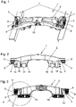
- chassis axle 2 of a chassis 1 shows a chassis axle 2 of a chassis 1 according to the invention, which can roll along with its rollers 3 on two rails 4.
- the chassis 1 can consist of a single chassis axle 2 of this type. However, several such chassis axles 2 can also be connected to one another to form a chassis 1 via the connection 33, for example by means of at least one longitudinal member or the like.
- a corresponding transport vehicle for transporting goods, in particular in intralogistics, is attached to the chassis 1 .
- the transport vehicle is known per se in the prior art in a wide variety of configurations and is not shown here.
- Running gears (1) according to the invention can be formed in a wide variety of configurations.
- the chassis axle(s) 2 can also be integrated directly into a floor of the transport vehicle or the like.
- the running gear 1 has two load-bearing rollers 3 .
- the rollers 3 are each rotatably mounted in a swivel arm 5 about a roller axis of rotation 6 for rolling on one of the rails 4 .
- the swivel arms 5 are each pivotably mounted on the chassis axis 2 together with the rollers 3 by means of a swivel joint 7 .
- the swivel arms 5 are each additionally supported by means of a support bearing 8 on the chassis axle 2 and the rollers 3 are arranged between the swivel joint 7 and the support bearing 8 .
- 2 shows a front view of the chassis axis 2, 3 a longitudinal section through this chassis axis 2.
- the running gear 1 in this exemplary embodiment has 2 guide rollers 14 arranged on the running gear axle 2, which are elastically pretensioned by means of a pretensioning device 15, which will be explained in detail later, in the direction of the respective rail 4 on which they rest. 4 shows area A 3 enlarged.
- the roller 3 is mounted on the swivel arm 5 so that it can rotate about its roller axis of rotation 6 by means of a ball bearing 20 .
- the guide roller 14 is also rotatably mounted about its guide roller axis of rotation 21 by means of a ball bearing 20 .
- the ball bearings 20 can also be replaced by other suitable bearings.
- roller axis of rotation 6 and the guide roller axis of rotation 21 are preferably orthogonal to one another. The same preferably also applies to the running surfaces of the running roller 3 on the one hand and the guide roller 14 on the other hand.
- the rails 4 are suitably formed with a corresponding right-angled bend in cross section, as shown here.
- the inventive design of the chassis 1 is particularly good in the front view according to figure 5 and in the sectional view arranged parallel thereto in 6 to see. It is easy to see here that the swivel arm 5 is pivotably mounted on the chassis axle 2 by means of the swivel joint 7 and is additionally supported on the chassis axle 2 by means of a support bearing 8, with the roller 3 being arranged between the swivel joint 7 and the support bearing 8. As a result, the loads resting on the chassis 1 or on the chassis axis 2 are entered symmetrically on both sides of the roller in the swivel arm 5, so that in the swivel joint 7 expensive angular ball bearings that are otherwise necessary in the prior art can be dispensed with.
- the pivot axis 9 of the pivot joint 7 about which the pivot arm 5 can be pivoted, runs parallel to the support direction 10 .
- the support bearing 8 is designed as a slide bearing. It allows the swivel arm 5 to be swiveled by means of the swivel joint 7 .
- the plain bearing has two sliding surfaces 11 and 12 which slide along one another when the pivot arm 5 is pivoted about the pivot axis 9 .
- one of the sliding surfaces, here the sliding surface 11 on the chassis axle 2 is made of metal, in particular steel.
- the other of the sliding surfaces, here the sliding surface 12 on the swivel arm 5 is advantageously made of a plastic. Suitable plastics were mentioned at the beginning. The coefficient of friction is favorably in the range of values mentioned at the outset.
- both sliding surfaces 11 and 12 are flat.
- the surface normal 13 to the flat areas of the sliding surfaces 11 and 12 runs parallel to the pivot axis 9 of the pivot joint 7.
- the roller axis of rotation 6, on the other hand, runs orthogonally to the pivot axis 9.
- the swivel joint 7 can also be of relatively simple design.
- it comprises a pivot slide bearing 22 in which two surfaces 23 and 24 slide against each other to allow pivotal movement.
- One of the surfaces, here the surface 23, is advantageously made of metal, in particular steel, and the other of the surfaces, here the surface 24, is again advantageously made of plastic.
- Both the surfaces 23 and 24 of this pivot slide bearing 22 and the sliding surfaces 11 and 12 of the support bearing 8 advantageously incorporate lubrication. How this can be configured specifically has already been explained at the outset.
- the Figures 7 to 10 show a preferred embodiment of a guide roller 14 used here in this exemplary embodiment, which is pressed against the rail by a pretensioning device 15.
- this prestressing device 15 also has a vibration damper 16 .
- 7 shows a view from the outside of the housing 17 or pressure piece, in which the guide roller 14, which is rotatable about its guide roller axis of rotation 21, is mounted in a linearly displaceable manner.
- the guide roller 14 is rotatably mounted with its ball bearing 20 in a roller carrier 25 .
- This role bearer 25 is mounted displaceably in the housing 17 together with the guide roller 14 in the longitudinal direction 34 .
- the biasing device 15 here has a helical biasing spring 26 which biases the plate 28 in the direction away from the throttle openings 30 .
- the roller carrier 25 and thus the guide roller 14 are supported on this plate 28 and thus on the prestressing spring 26 of the prestressing device 15 .
- a damping piston 27 is arranged on it on the side facing away from the guide roller 14, which is slidably mounted in a guide channel 35 of the damper housing 31 in the longitudinal direction 34.
- the damper housing 31 is designed here as a partial area of the housing 17, which of course does not necessarily have to be the case.
- the plate 28 is in any case sealed against the damper housing 31 by means of the seal 29 .
- a pressure chamber is formed in the damper housing 31, which is only connected to the environment via the throttle openings 30.
- this partial volume between the plate 28 and the throttle openings 30 within the damper housing 31 forms a pneumatic vibration damper 16.
- the opening cross sections of the throttle openings 30 can be selected such that the desired damping effect is achieved. The damping effect arises when compressing and thus when reducing the partial volume between plate 28 and throttle openings 30, in that the air can only escape through the throttle openings 30 to the outside in a slowed down manner.
- the throttle openings 30 also have a throttling effect when air enters the partial volume between plate 28 and throttle opening 30 from the outside, so that the desired damping effect also occurs in this direction.
- the integration of pretensioning device 15 and vibration damper 16 results in this exemplary embodiment from the fact that, on the one hand, the prestressing spring 26 is arranged in the interior of the damper housing 31 and, on the other hand, the described vibration damper 16 is also positively coupled to the prestressing device 15.
- the variant of the pretensioning device 15 shown here as an example acts linearly in a longitudinal direction 34 on the guide roller 14 in order to press it against the rail 4 .
- the guide roller 14 with its housing 17 or pressure piece can be fastened to the chassis axle 2 without tools and can also be removed from it again.
- this is achieved in that the housing 17 is held between fastening clamps 18 and a support 19 of the chassis axle 2 and can thus be removed from the chassis axle 2 at any time and replaced by another guide roller 14 with its housing 17, optionally with a stronger or weaker pretensioning device 15, can be exchanged.
- the chassis axle 2 preferably consists at least largely of a plastic, particularly preferably of a fiber-reinforced plastic.
- the chassis axis can be built very light and yet very stable, whereby the forces of inertia to be overcome when accelerating and braking the transport vehicle be reduced.
- such chassis axles made of plastic or fiber-reinforced plastic can be produced relatively cheaply.
Landscapes
- Engineering & Computer Science (AREA)
- Mechanical Engineering (AREA)
- Transportation (AREA)
- Bearings For Parts Moving Linearly (AREA)
- Rolling Contact Bearings (AREA)
Applications Claiming Priority (1)
| Application Number | Priority Date | Filing Date | Title |
|---|---|---|---|
| ATA280/2020A AT524624B1 (de) | 2020-12-21 | 2020-12-21 | Fahrwerk für ein schienengebundenes Transportfahrzeug |
Publications (3)
| Publication Number | Publication Date |
|---|---|
| EP4015341A1 true EP4015341A1 (fr) | 2022-06-22 |
| EP4015341C0 EP4015341C0 (fr) | 2024-05-22 |
| EP4015341B1 EP4015341B1 (fr) | 2024-05-22 |
Family
ID=78819820
Family Applications (1)
| Application Number | Title | Priority Date | Filing Date |
|---|---|---|---|
| EP21211190.0A Active EP4015341B1 (fr) | 2020-12-21 | 2021-11-30 | Train de roulement pour un véhicule de transport sur rails |
Country Status (5)
| Country | Link |
|---|---|
| US (1) | US20220194439A1 (fr) |
| EP (1) | EP4015341B1 (fr) |
| CN (1) | CN114644197A (fr) |
| AT (1) | AT524624B1 (fr) |
| ES (1) | ES2983167T3 (fr) |
Families Citing this family (1)
| Publication number | Priority date | Publication date | Assignee | Title |
|---|---|---|---|---|
| AT527639A1 (de) | 2023-09-28 | 2025-04-15 | Faigle Kunststoffe Gmbh | Laufrollenanordnung |
Citations (3)
| Publication number | Priority date | Publication date | Assignee | Title |
|---|---|---|---|---|
| DE849568C (de) * | 1942-12-17 | 1952-09-15 | Brown Ag | Einrichtung zur Erzielung eines stossfreien Laufes der Radsaetze von schweren Schienen-Triebfahrzeugen |
| DE1150403B (de) * | 1957-01-29 | 1963-06-20 | Krauss Maffei Ag | Achslenker zum Fuehren der Radsaetze von Schienen- und Strassenfahrzeugen in Laengs-und Querrichtung |
| WO2016068705A1 (fr) | 2014-10-28 | 2016-05-06 | Vanderlande Industries B.V. | Dispositif pour acheminer des produits |
Family Cites Families (9)
| Publication number | Priority date | Publication date | Assignee | Title |
|---|---|---|---|---|
| DE3709530C2 (de) * | 1987-03-23 | 1998-05-20 | Mannesmann Ag | Fahrwerk mit Laufrädern |
| CH687616A5 (de) * | 1994-06-08 | 1997-01-15 | Grapha Holding Ag | Wagenkette fuer eine Sortieranlage. |
| KR101013126B1 (ko) * | 2010-06-03 | 2011-02-10 | 재단법인 한국계면공학연구소 | 철도 차량용 자기 조향 장치 |
| US8851267B2 (en) * | 2012-03-26 | 2014-10-07 | Mantissa Corporation | High efficiency sorting conveyor with improved friction drive motor assembly |
| DE102012214929A1 (de) * | 2012-08-22 | 2014-02-27 | Wirtgen Gmbh | Straßenfräsmaschine zum Bearbeiten von Straßenbelägen, sowie Verfahren zum Verschwenken eines Laufwerks einer Straßenfräsmaschine |
| CN109835364B (zh) * | 2017-11-24 | 2020-11-27 | 比亚迪汽车工业有限公司 | 一种转向架及具有其的轨道交通系统 |
| AT520732B1 (de) * | 2018-07-05 | 2019-07-15 | Faigle Kunststoffe Gmbh | Einrichtung umfassend eine Laufrolle und eine die Laufrolle tragende Aufhängung |
| DE102018116992A1 (de) * | 2018-07-13 | 2020-01-16 | Beckhoff Automation Gmbh | Transportsystem und Transportvorrichtung |
| US12703406B2 (en) * | 2022-04-29 | 2026-08-11 | Zhuzhou Times New Material Technology Co., Ltd. | Method for improving curvilinear running speed of railway vehicle and smart tilting system |
-
2020
- 2020-12-21 AT ATA280/2020A patent/AT524624B1/de active
-
2021
- 2021-11-30 EP EP21211190.0A patent/EP4015341B1/fr active Active
- 2021-11-30 ES ES21211190T patent/ES2983167T3/es active Active
- 2021-12-21 CN CN202111571257.9A patent/CN114644197A/zh active Pending
- 2021-12-21 US US17/557,202 patent/US20220194439A1/en not_active Abandoned
Patent Citations (3)
| Publication number | Priority date | Publication date | Assignee | Title |
|---|---|---|---|---|
| DE849568C (de) * | 1942-12-17 | 1952-09-15 | Brown Ag | Einrichtung zur Erzielung eines stossfreien Laufes der Radsaetze von schweren Schienen-Triebfahrzeugen |
| DE1150403B (de) * | 1957-01-29 | 1963-06-20 | Krauss Maffei Ag | Achslenker zum Fuehren der Radsaetze von Schienen- und Strassenfahrzeugen in Laengs-und Querrichtung |
| WO2016068705A1 (fr) | 2014-10-28 | 2016-05-06 | Vanderlande Industries B.V. | Dispositif pour acheminer des produits |
Also Published As
| Publication number | Publication date |
|---|---|
| EP4015341C0 (fr) | 2024-05-22 |
| EP4015341B1 (fr) | 2024-05-22 |
| AT524624A1 (de) | 2022-07-15 |
| US20220194439A1 (en) | 2022-06-23 |
| CN114644197A (zh) | 2022-06-21 |
| AT524624B1 (de) | 2023-09-15 |
| ES2983167T3 (es) | 2024-10-22 |
Similar Documents
| Publication | Publication Date | Title |
|---|---|---|
| WO2021175389A1 (fr) | Chariot de transport pour un convoyeur distributeur et ensemble de raccordement pour fixer un chariot de transport à un moyen d'entraînement d'un convoyeur distributeur | |
| DE102012100287B4 (de) | Fahrzeugsitz | |
| EP3752694B1 (fr) | Dispositif de stationnement de voiture | |
| DE102008029275A1 (de) | Lineareinheit | |
| EP1457692B1 (fr) | Guidage linéaire | |
| EP4015341B1 (fr) | Train de roulement pour un véhicule de transport sur rails | |
| DE2817741A1 (de) | Umlenkbeschlag fuer sicherheitsgurte, insbesondere fuer kraftfahrzeuge | |
| EP3283411B1 (fr) | Dispositif de liaison, chariot de transport et système de transport | |
| DE19519153C2 (de) | Führung für verstellbare Fahrzeugsitze | |
| EP4530093B1 (fr) | Dispositif de galet de roulement | |
| DE102007013516B4 (de) | Linearwälzlager | |
| EP0779174A2 (fr) | Réglage en longueur d'un siège | |
| DE102020210443A1 (de) | Laufwagenanordnung mit wälzlagergeführter Kraftabtragung in Verschieberichtung sowie Fenster oder Tür mit einer solchen Laufwagenanordnung | |
| DE202012004830U1 (de) | Betätigungseinheit für eine Sortiervorrichtung von Stückgütern | |
| EP4313832B1 (fr) | Guidage à rouleaux permettant de guider une cabine d'ascenseur ou un contrepoids d'ascenseur | |
| DE202019104015U1 (de) | Schwenkbare Beförderungsvorrichtung | |
| DE102020102828B4 (de) | Raupenantrieb für lagerfahrzeug | |
| WO2019110323A1 (fr) | Chemin de roulement, dispositif de transport et procédé de montage d'un chemin de roulement | |
| DE102004062764A1 (de) | Rollenwagen | |
| DE102022205320A1 (de) | Vorrichtung zum Sortieren von Stückgütern | |
| DE4330133A1 (de) | Schienenführung für Fahrzeugsitze | |
| DE102014206384B4 (de) | Rollenwagen | |
| EP4045438B1 (fr) | Dispositif d'entraînement pour un chariot d'un système de transport | |
| DE19746776A1 (de) | Vorrichtung zur verschiebbaren Lagerung von Aufzugstürblättern | |
| DE102018116672A1 (de) | Rückensteife Stauförderkette |
Legal Events
| Date | Code | Title | Description |
|---|---|---|---|
| PUAI | Public reference made under article 153(3) epc to a published international application that has entered the european phase |
Free format text: ORIGINAL CODE: 0009012 |
|
| STAA | Information on the status of an ep patent application or granted ep patent |
Free format text: STATUS: THE APPLICATION HAS BEEN PUBLISHED |
|
| AK | Designated contracting states |
Kind code of ref document: A1 Designated state(s): AL AT BE BG CH CY CZ DE DK EE ES FI FR GB GR HR HU IE IS IT LI LT LU LV MC MK MT NL NO PL PT RO RS SE SI SK SM TR |
|
| STAA | Information on the status of an ep patent application or granted ep patent |
Free format text: STATUS: REQUEST FOR EXAMINATION WAS MADE |
|
| 17P | Request for examination filed |
Effective date: 20221031 |
|
| RBV | Designated contracting states (corrected) |
Designated state(s): AL AT BE BG CH CY CZ DE DK EE ES FI FR GB GR HR HU IE IS IT LI LT LU LV MC MK MT NL NO PL PT RO RS SE SI SK SM TR |
|
| P01 | Opt-out of the competence of the unified patent court (upc) registered |
Effective date: 20230512 |
|
| GRAP | Despatch of communication of intention to grant a patent |
Free format text: ORIGINAL CODE: EPIDOSNIGR1 |
|
| STAA | Information on the status of an ep patent application or granted ep patent |
Free format text: STATUS: GRANT OF PATENT IS INTENDED |
|
| INTG | Intention to grant announced |
Effective date: 20240301 |
|
| GRAS | Grant fee paid |
Free format text: ORIGINAL CODE: EPIDOSNIGR3 |
|
| GRAA | (expected) grant |
Free format text: ORIGINAL CODE: 0009210 |
|
| STAA | Information on the status of an ep patent application or granted ep patent |
Free format text: STATUS: THE PATENT HAS BEEN GRANTED |
|
| AK | Designated contracting states |
Kind code of ref document: B1 Designated state(s): AL AT BE BG CH CY CZ DE DK EE ES FI FR GB GR HR HU IE IS IT LI LT LU LV MC MK MT NL NO PL PT RO RS SE SI SK SM TR |
|
| REG | Reference to a national code |
Ref country code: GB Ref legal event code: FG4D Free format text: NOT ENGLISH |
|
| REG | Reference to a national code |
Ref country code: CH Ref legal event code: EP |
|
| REG | Reference to a national code |
Ref country code: DE Ref legal event code: R096 Ref document number: 502021003789 Country of ref document: DE |
|
| REG | Reference to a national code |
Ref country code: IE Ref legal event code: FG4D Free format text: LANGUAGE OF EP DOCUMENT: GERMAN |
|
| P04 | Withdrawal of opt-out of the competence of the unified patent court (upc) registered |
Free format text: CASE NUMBER: APP_33276/2024 Effective date: 20240604 |
|
| U01 | Request for unitary effect filed |
Effective date: 20240605 |
|
| U07 | Unitary effect registered |
Designated state(s): AT BE BG DE DK EE FI FR IT LT LU LV MT NL PT SE SI Effective date: 20240620 |
|
| PG25 | Lapsed in a contracting state [announced via postgrant information from national office to epo] |
Ref country code: IS Free format text: LAPSE BECAUSE OF FAILURE TO SUBMIT A TRANSLATION OF THE DESCRIPTION OR TO PAY THE FEE WITHIN THE PRESCRIBED TIME-LIMIT Effective date: 20240922 |
|
| PG25 | Lapsed in a contracting state [announced via postgrant information from national office to epo] |
Ref country code: HR Free format text: LAPSE BECAUSE OF FAILURE TO SUBMIT A TRANSLATION OF THE DESCRIPTION OR TO PAY THE FEE WITHIN THE PRESCRIBED TIME-LIMIT Effective date: 20240522 |
|
| PG25 | Lapsed in a contracting state [announced via postgrant information from national office to epo] |
Ref country code: GR Free format text: LAPSE BECAUSE OF FAILURE TO SUBMIT A TRANSLATION OF THE DESCRIPTION OR TO PAY THE FEE WITHIN THE PRESCRIBED TIME-LIMIT Effective date: 20240823 |
|
| REG | Reference to a national code |
Ref country code: ES Ref legal event code: FG2A Ref document number: 2983167 Country of ref document: ES Kind code of ref document: T3 Effective date: 20241022 |
|
| U20 | Renewal fee for the european patent with unitary effect paid |
Year of fee payment: 4 Effective date: 20240918 |
|
| PG25 | Lapsed in a contracting state [announced via postgrant information from national office to epo] |
Ref country code: PL Free format text: LAPSE BECAUSE OF FAILURE TO SUBMIT A TRANSLATION OF THE DESCRIPTION OR TO PAY THE FEE WITHIN THE PRESCRIBED TIME-LIMIT Effective date: 20240522 |
|
| PG25 | Lapsed in a contracting state [announced via postgrant information from national office to epo] |
Ref country code: PL Free format text: LAPSE BECAUSE OF FAILURE TO SUBMIT A TRANSLATION OF THE DESCRIPTION OR TO PAY THE FEE WITHIN THE PRESCRIBED TIME-LIMIT Effective date: 20240522 Ref country code: NO Free format text: LAPSE BECAUSE OF FAILURE TO SUBMIT A TRANSLATION OF THE DESCRIPTION OR TO PAY THE FEE WITHIN THE PRESCRIBED TIME-LIMIT Effective date: 20240822 Ref country code: IS Free format text: LAPSE BECAUSE OF FAILURE TO SUBMIT A TRANSLATION OF THE DESCRIPTION OR TO PAY THE FEE WITHIN THE PRESCRIBED TIME-LIMIT Effective date: 20240922 Ref country code: HR Free format text: LAPSE BECAUSE OF FAILURE TO SUBMIT A TRANSLATION OF THE DESCRIPTION OR TO PAY THE FEE WITHIN THE PRESCRIBED TIME-LIMIT Effective date: 20240522 Ref country code: GR Free format text: LAPSE BECAUSE OF FAILURE TO SUBMIT A TRANSLATION OF THE DESCRIPTION OR TO PAY THE FEE WITHIN THE PRESCRIBED TIME-LIMIT Effective date: 20240823 Ref country code: RS Free format text: LAPSE BECAUSE OF FAILURE TO SUBMIT A TRANSLATION OF THE DESCRIPTION OR TO PAY THE FEE WITHIN THE PRESCRIBED TIME-LIMIT Effective date: 20240822 |
|
| PG25 | Lapsed in a contracting state [announced via postgrant information from national office to epo] |
Ref country code: CZ Free format text: LAPSE BECAUSE OF FAILURE TO SUBMIT A TRANSLATION OF THE DESCRIPTION OR TO PAY THE FEE WITHIN THE PRESCRIBED TIME-LIMIT Effective date: 20240522 |
|
| PG25 | Lapsed in a contracting state [announced via postgrant information from national office to epo] |
Ref country code: SK Free format text: LAPSE BECAUSE OF FAILURE TO SUBMIT A TRANSLATION OF THE DESCRIPTION OR TO PAY THE FEE WITHIN THE PRESCRIBED TIME-LIMIT Effective date: 20240522 Ref country code: RO Free format text: LAPSE BECAUSE OF FAILURE TO SUBMIT A TRANSLATION OF THE DESCRIPTION OR TO PAY THE FEE WITHIN THE PRESCRIBED TIME-LIMIT Effective date: 20240522 |
|
| PGFP | Annual fee paid to national office [announced via postgrant information from national office to epo] |
Ref country code: ES Payment date: 20241216 Year of fee payment: 4 |
|
| PG25 | Lapsed in a contracting state [announced via postgrant information from national office to epo] |
Ref country code: SK Free format text: LAPSE BECAUSE OF FAILURE TO SUBMIT A TRANSLATION OF THE DESCRIPTION OR TO PAY THE FEE WITHIN THE PRESCRIBED TIME-LIMIT Effective date: 20240522 Ref country code: RO Free format text: LAPSE BECAUSE OF FAILURE TO SUBMIT A TRANSLATION OF THE DESCRIPTION OR TO PAY THE FEE WITHIN THE PRESCRIBED TIME-LIMIT Effective date: 20240522 Ref country code: CZ Free format text: LAPSE BECAUSE OF FAILURE TO SUBMIT A TRANSLATION OF THE DESCRIPTION OR TO PAY THE FEE WITHIN THE PRESCRIBED TIME-LIMIT Effective date: 20240522 |
|
| PGFP | Annual fee paid to national office [announced via postgrant information from national office to epo] |
Ref country code: CH Payment date: 20241201 Year of fee payment: 4 |
|
| REG | Reference to a national code |
Ref country code: DE Ref legal event code: R097 Ref document number: 502021003789 Country of ref document: DE |
|
| PLBE | No opposition filed within time limit |
Free format text: ORIGINAL CODE: 0009261 |
|
| STAA | Information on the status of an ep patent application or granted ep patent |
Free format text: STATUS: NO OPPOSITION FILED WITHIN TIME LIMIT |
|
| 26N | No opposition filed |
Effective date: 20250225 |
|
| PG25 | Lapsed in a contracting state [announced via postgrant information from national office to epo] |
Ref country code: MC Free format text: LAPSE BECAUSE OF FAILURE TO SUBMIT A TRANSLATION OF THE DESCRIPTION OR TO PAY THE FEE WITHIN THE PRESCRIBED TIME-LIMIT Effective date: 20240522 |
|
| PG25 | Lapsed in a contracting state [announced via postgrant information from national office to epo] |
Ref country code: IE Free format text: LAPSE BECAUSE OF NON-PAYMENT OF DUE FEES Effective date: 20241130 |
|
| PG25 | Lapsed in a contracting state [announced via postgrant information from national office to epo] |
Ref country code: CY Free format text: LAPSE BECAUSE OF FAILURE TO SUBMIT A TRANSLATION OF THE DESCRIPTION OR TO PAY THE FEE WITHIN THE PRESCRIBED TIME-LIMIT; INVALID AB INITIO Effective date: 20211130 |
|
| PG25 | Lapsed in a contracting state [announced via postgrant information from national office to epo] |
Ref country code: SM Free format text: LAPSE BECAUSE OF FAILURE TO SUBMIT A TRANSLATION OF THE DESCRIPTION OR TO PAY THE FEE WITHIN THE PRESCRIBED TIME-LIMIT; INVALID AB INITIO Effective date: 20211130 |
|
| PG25 | Lapsed in a contracting state [announced via postgrant information from national office to epo] |
Ref country code: TR Free format text: LAPSE BECAUSE OF FAILURE TO SUBMIT A TRANSLATION OF THE DESCRIPTION OR TO PAY THE FEE WITHIN THE PRESCRIBED TIME-LIMIT Effective date: 20240522 |
|
| PG25 | Lapsed in a contracting state [announced via postgrant information from national office to epo] |
Ref country code: HU Free format text: LAPSE BECAUSE OF FAILURE TO SUBMIT A TRANSLATION OF THE DESCRIPTION OR TO PAY THE FEE WITHIN THE PRESCRIBED TIME-LIMIT; INVALID AB INITIO Effective date: 20211130 |
|
| REG | Reference to a national code |
Ref country code: CH Ref legal event code: H13 Free format text: ST27 STATUS EVENT CODE: U-0-0-H10-H13 (AS PROVIDED BY THE NATIONAL OFFICE) Effective date: 20260623 |
|
| U90 | Renewal fees not paid: noting of loss of rights |
Free format text: RENEWAL FEE NOT PAID FOR YEAR 05 Effective date: 20260616 |
|
| PG25 | Lapsed in a contracting state [announced via postgrant information from national office to epo] |
Ref country code: CH Free format text: LAPSE BECAUSE OF NON-PAYMENT OF DUE FEES Effective date: 20251130 |