EP4016094A1 - Procédé et dispositif de détection des tensions électriques et/ou des courants électriques - Google Patents
Procédé et dispositif de détection des tensions électriques et/ou des courants électriques Download PDFInfo
- Publication number
- EP4016094A1 EP4016094A1 EP21213754.1A EP21213754A EP4016094A1 EP 4016094 A1 EP4016094 A1 EP 4016094A1 EP 21213754 A EP21213754 A EP 21213754A EP 4016094 A1 EP4016094 A1 EP 4016094A1
- Authority
- EP
- European Patent Office
- Prior art keywords
- electrical
- data
- calculated data
- detection
- spatial positions
- Prior art date
- Legal status (The legal status is an assumption and is not a legal conclusion. Google has not performed a legal analysis and makes no representation as to the accuracy of the status listed.)
- Granted
Links
Images


Classifications
-
- G—PHYSICS
- G01—MEASURING; TESTING
- G01R—MEASURING ELECTRIC VARIABLES; MEASURING MAGNETIC VARIABLES
- G01R29/00—Arrangements for measuring or indicating electric quantities not covered by groups G01R19/00 - G01R27/00
- G01R29/12—Measuring electrostatic fields or voltage-potential
- G01R29/14—Measuring field distribution
Definitions
- the present invention relates to a method and a device for detecting electrical current and/or electrical voltage by recognizing the position and/or the technical and physical properties of current-carrying or voltage-carrying objects and components in an environment, e.g. using methods based on artificial intelligence .
- Line detectors are known from the prior art, which detect power lines hidden in walls. Among other things, this helps to prevent a line from being unexpectedly hit when drilling holes in walls, for example, which could result in an electrical accident.
- a locating device also known as a line locator, line finder, beam finder or multi-detector
- a locating device is used, especially in the context of building services, to locate invisible objects within walls, ceilings and floors such as electrical lines, but also water and gas lines, iron reinforcements or stand constructions .
- detection is mostly based on the detection of electric, magnetic or electromagnetic fields induced by electric currents.
- the electrical, magnetic or electromagnetic fields of the aforementioned measuring devices are usually determined using a single method.
- an electric field can be determined using a capacitive method.
- WO 2018/111474 A1 describes a warning device for detecting electrically charged conductors.
- One or more field-detecting sensors are configured to detect a charged conductor that is proximate to the location of the warning device by sensing appropriate electric and/or magnetic fields.
- an approximate direction in which the conductor is located in relation to the location of the warning device is recognized.
- EP 3 144 686 A1 describes a safety element against the risk of electric shock.
- the security element comprises detection means for detecting measurement signals of an electric field and alarm means for generating a warning signal.
- detection means for detecting measurement signals of an electric field
- alarm means for generating a warning signal.
- movement measuring element for measuring a movement of the protective device and a control unit which processes the detected electric field measuring signals and calculates their variation when the personal protective device is moved through the electric field.
- EP 3 124 983 B1 describes a personal safety system that attaches to a protective helmet and includes a voltage detector to detect an ambient electric field and a signaling system to send a signaling signal to a person when the voltage detector detects an ambient electric field that is greater than a detection threshold .
- the invention includes a method for the automated detection of one or more electrical voltages and/or electrical currents.
- the method here comprises providing calculated data on the one or more electrical voltages and/or electrical currents, the calculated data comprising the spatial positions of at least one carrier of the one or more electrical voltages and/or electrical currents and the calculated Data have been calculated from a set of measurement data for a plurality of first detections of the one or more electrical voltages and/or the electrical currents.
- the method further includes performing a second detection of the one or more electrical voltages and/or the electrical currents, measurement data for the second detection being generated during the second detection, and calculated data being updated from the measurement data of the second detection and the calculated data the one or more electrical voltages and/or the electrical currents are generated.
- the circumnavigation additionally comprises outputting the updated calculated data to indicate the spatial positions and/or the properties of the at least one carrier of the one or more electrical voltages and/or the electrical currents.
- the invention includes a device for the automated detection of one or more electrical voltages and / or electrical currents, comprising means for providing calculated data on the one or more electrical voltages and / or electrical currents, the calculated data the spatial Positions of at least one carrier of the one or more electrical voltages and/or the electrical currents and wherein the calculated data have been calculated from a set of measurement data for a plurality of first detections of the one or more electrical voltages and/or the electrical currents.
- the device also includes means for performing a second detection of the one or more electrical voltages and/or the electrical currents, with measurement data relating to the second detection being performed in the second detection Detection are generated, and updated calculated data on the one or more electrical voltages and / or electrical currents are generated from the measurement data of the second detection and the calculated data.
- the device additionally comprises means for outputting the updated calculated data in order to display the spatial positions and/or the properties of the at least one carrier of the one or more electrical voltages and/or the electrical currents.
- the invention comprises a display device for outputting at least one signal, comprising the device according to any one of the preceding claims, wherein the at least one signal comprises the at least one output signal according to any one of the preceding claims.
- FIG. 1 shows a schematic of a transformer station, as is used, for example, to convert supply voltages in electrical supply networks.
- the parts that carry electricity would be the electrical lines 1 and the transformer 2.
- a power accident can be caused not only by direct contact with live or live components, but also as a result of an arc that can occur , if a person gets too close to the high-voltage inputs 4 on the transformer 2, for example.
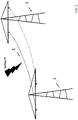
- FIG. 2 a section of an overhead power line is shown.
- the high-voltage lines 1 are stretched between two transmission masts 3, which lines can, for example, comprise three separate lines for the transmission of three-phase alternating current.
- a danger to people can, for example, be that if one of the lines 1 is switched off in the course of work to be carried out (which is FIG. 2 represented by the dashed line) a person mistakenly charged the high-voltage line 1 (in FIG. 2 shown as a solid line) comes too close and an arc flash accident may occur.
- FIG. 3 shows a transformer station in which two high-voltage cells 5 and 6 are supplied by a transformer 2 via a busbar 8.
- Cell 5 is connected to the transformer 2 and is fully live, as is the busbar 8, whereas cell 6 is disconnected from the transformer 2 by a switch, ie is only partially live, ie in the upper access part.
- a person who has to work in the switched-off cell 6 can erroneously enter the live cell 5 that has not been switched off, for example as a result of confusion or carelessness, and suffer an electrical accident there.
- a timely warning to the person concerned, for example when approaching or entering cell 5, can be displayed in this case of life-saving importance.
- the person is at risk of suffering an electrical accident from the upper parts of the switched-off cell 6 being live
- FIG. 4 shows the transformer station FIG. 3 , in which a defect 7 has occurred in the switched-off cell 6, the defect 7 bringing about the effect that the cell 6 is still completely under voltage despite having been switched off.
- This can lead to a life-threatening situation for the aforementioned person, who is actually in the correct assumption that the cell 6 is not live in the lower area and work carried out in accordance with the regulations does not pose a danger, if they enter the defective cell 6 and use the work is started. In this case, too, a timely warning to the person would be of crucial importance.
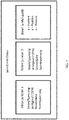
- the method includes providing calculated data on one or more electrical voltages and/or electrical currents, as in FIG. 5 shown in method step 10.
- the calculated data include the spatial positions of at least one carrier of one or more electrical voltages and / or electrical currents, such as the spatial positions of the current-carrying lines 1 from the FIG. 1 and 2 or cells 5 and 6 from the FIG. 3 and 4 .
- the electrical currents can include direct currents and alternating currents.
- the calculated data are calculated from a set of measurement data for a plurality of first detections of the one or more electrical voltages and/or the electrical currents, for example the currents in the lines 1 or the cells 5 and 6 .
- the method according to the invention further comprises, in a method step 11, carrying out a second detection of the one or more electrical voltages and/or the electrical currents, such as the currents in the lines 1, measurement data being generated in a method step 12 during the second detection, and in in a method step 13, updated calculated data on the one or more electrical voltages and/or the electrical currents, for example on the electrical currents in the lines 1 or the cells 5 and 6, are generated from the measurement data of the second detection and the calculated data.
- the calculated data as well as the updated calculated data can be in electronic and/or machine-readable form and in such formats or can be converted that they can be read by software programs, for example from an evaluation means 104 FIG. 6 applied, read and processed.
- the updated calculated data are displayed, for example, on a screen such as screen 105 FIG. 17 , issued to about a person's spatial Display positions and / or the properties of at least one carrier of the one or more electrical voltages and / or electrical currents.
- the majority of the first detections can be carried out in a method that is completely separate from the second detection.
- the majority of the first detections can be carried out with a different measuring device than in the case of the second detection.
- the first and the second detection can be carried out at different points in time.
- the calculation of the updated set of calculated data can be done using self-learning systems and artificial intelligence.
- the method further comprises the provision of a plurality of detection means for detecting a plurality of measured variables, the plurality of measured variables being properties of the one or more electrical voltages and/or electrical currents, such as the electrical currents in the lines 1 of FIG. 1 and 2 or in cells 5 and 6 in den FIG. 3 and 4 , Determine and wherein at least one measured variable quantitatively determines the properties of electric and / or magnetic and / or electromagnetic fields.
- the spatial positions or locations of the at least one carrier of the one or more electrical voltages and/or the electrical current, such as the spatial positions of the lines 1 or the cells 5 and 6, are determined from at least one measured variable, and the spatial positions from at least one measured variable Positions of the plurality of detection means, wherein the detection means may be attached to a movable support such as a person.
- the spatial positions can also include states of motion.
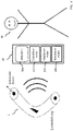
- the detection means 101 and 102 can detect measured variables in connection with electrical and/or magnetic and/or electromagnetic fields, which indicate the presence of electrical voltages and currents in the lines 1 or the cells 5 and 6, for example.
- the spatial positions and locations of the electrical lines 1 or the cells 5 and 6 can then be determined from these measured variables.
- Physical variables such as current and voltage can be determined from the aforementioned measured variables.
- B. in the case of malfunction 7 in the shutdown of the cell 6 in FIG. 4 occur can be detected.
- the detection means 101 and 102 can detect damage to electrical systems or their possible malfunctions, which are approximately schematically illustrated by the malfunction 7 in the switched-off cell 6 in FIG. 4 are shown.
- the detection means 101, 102 and 103 can also detect measured variables which indicate environmental conditions, such as B. the air pressure, which prevails in the vicinity of the lines 1.
- the detection means 103 can, for example, detect a measured variable in connection with the spatial position and/or a state of motion of the device 100 or at least one of the detection means 101 or 102. The corresponding spatial positions and/or the movement states of the device 100 and the detection means 101, 102 and 103 can then be determined from this. For example, it can be determined at what height a person is currently located on the transfer mast 3 when this person is just climbing up the transfer mast 3 and is carrying the device 100 with them. In this way, the distance that the person currently has from the lines 1 can also be determined.
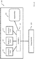
- the method involves the provision of at least one evaluation means 104 to obtain measurement data from the plurality of measured variables, for example on the spatial positions of the at least one carrier of the one or more electrical voltages and/or the electrical currents and/or on the spatial positions and/or the states of motion of the plurality of detection means, such as the detection means 101, 102 and 103.
- the device further includes the provision of an output means 105 to generate at least one output signal, wherein the at least one output signal is generated based on the calculated data and the measurement data of the second detection and/or the updated calculated data.
- the output means 105 is integrated into the device, as in FIG. 6 shown schematically, and may for example comprise a loudspeaker which emits an acoustic warning signal when a person comes too close to live lines 1 or cells 5 and 6.
- the output means 105 can comprise a screen on which the spatial position of the voltage-carrying and current-carrying components present in the area is displayed (see screen 105 of FIG. 17 ), such as the lines 1 in the FIG. 1 and 2 or cells 5 and 6 in den FIG. 3 and 4 .
- Device 100 may include memory for storing data 106, as discussed in more detail below.
- the position and the technical and physical properties of the components such as the lines 1 or the cells 5 and 6 are calculated, for example, by the device 100, for example using the evaluation means 104, on the basis of the calculated data and the measurement data of the second detection.
- the calculated data can be available to the device 100 and/or the evaluation means 104 without the device 100 and/or the evaluation means 104 having to perform further calculations with regard to the calculated data.
- the calculated data and/or the updated calculated data can include further properties of the electrical voltages and/or the electrical currents present in the carriers.
- some further properties are shown as examples, which are included. These are approximately the corresponding current intensities and current voltages which are applied to the lines 1 and the cell 5 that is not switched off.
- the calculated data for a measuring device for example the device 100, does not contain any additional data on other properties in addition to the data on the spatial position.
- the calculated data on the gauge may also include such additional data as data on the environmental conditions of the conductors.
- At least one measured variable can be a field strength, a flux density, a change in field strength, a change in flux density, a capacitance, a sound associated with the presence of one or more electrical voltages and/or currents and/or a temporal and/or spatial change in the aforementioned measured variables and/or measured variables derived from the aforementioned measured variables.
- the at least one measured variable associated with the spatial positions of the plurality of detection means 101, 102 and 103 can be the geomagnetic field occurring at the spatial positions of the plurality of detection means 101, 102 and 103 and/or the at the spatial positions of the plurality of Detection means 101, 102 and 103 occurring air pressure and / or at spatial positions of the plurality of detection means occurring ultrasound.
- the detection means can comprise a device for measuring the ambient air pressure. For example, by measuring a height-dependent air pressure, the height can be determined at which a person is currently located when they are about one of the pylons 3 in the FIG. 3 climbs up to do work on the pylon 3, for example. Should the altitude air pressure indicate that a certain altitude has been exceeded and that the person is close to the live lines 1 threatens to come too close and there is a risk of an electric arc, then a warning can be displayed to the person via the output means 105 .
- the measured variable detected by the detection means 101 is an electric field caused by capacitances in a DC system (e.g. battery, fuel cell, solar system).
- a DC system e.g. battery, fuel cell, solar system
- an electric field can also be generated by a voltage which is applied to a component, for example the defect 7 in the switched-off cell 6, due to a malfunction or damage.
- the measured variable detected by the detection means 102 includes, for example, a sound pressure, such as is generated by the structure-borne noise of a component (eg an electric motor) through which electric current flows.
- the measured variable detected by the detection means 102 for example, can also include the magnetic field generated by the electric current.
- the measured variable detected by the detection means 103 can include a current flow induced by the earth's magnetic field or the position of an antenna connected to the detection means 103 as part of a GPS-based position determination.
- the detection means 103 can also include measured variables relating to the ambient air pressure or to IMU data.
- the calculated data can additionally, as is shown schematically in FIG. 9 is shown, comprising the spatial movement and/or the acceleration of the plurality of detection means.
- the spatial movement can include translational and rotational components.
- the spatial movement is the first derivation of the spatial position over time, i.e. it includes different spatial positions of the detection means at different measurement times, and the acceleration is the second derivation of the spatial position over time, i.e. it includes the difference between two spatial positions that lead to the Difference of the corresponding measurement times occurs.
- the spatial movement and the acceleration can be determined using the orientation of the device 100 and/or the detection means 101, 102, 103 to the gravitational vector.
- the detection means 101, 103, 103 can also include motion and acceleration sensors, which are based, for example, on MEMS technology or include gyrometers or piezoelectric elements.
- the evaluation means 104 can comprise a program-controlled computer which is integrated into the device 100 according to the invention.
- the evaluation means 104 can be integrated in the device 100, as in FIG FIG. 6 shown, and in yet another embodiment, the evaluation means 104 can be located at a location remote from the device 100, for example at a central server station.
- FIG. 10 the embodiment is shown schematically in which the evaluation means 104 is located at a location remote from the device 100 .
- the device 100 can include an interface 107 via which data, such as measurement data, are transmitted from the device 100 to the evaluation means 104 .
- the transmission can be wired and/or wireless.
- a wireless transmission can be carried out, for example, via radio or via infrared radiation.
- the interface 107 can also be used to transmit the calculated data generated from the measurement data to the device 100 in order, for example, to display the local positions of the lines 1 or the position of a carrier of the device 100 or to issue a warning.
- the output means 105 can be located at a location remote from the device 100, for example at the location where the personnel for possible repair and maintenance work are located, whereas the device 100 is located, for example, on a remote-controlled or autonomously moving, mobile robot unit is located.
- Data can be transmitted between the device 100 and the output means 105 via the interface 107 .
- the transmission can be wired and/or wireless.
- a wireless transmission can be carried out, for example, via radio or via infrared radiation.
- the output means 105 comprises a screen, for example to display the location of those components in a relevant environment that carry electrical voltages or carry electrical currents.
- the display means 105 can comprise a head-up display, which is mounted on a helmet, such as a safety helmet, for example. In such a head-up display, for example, the position of the voltage-carrying and current-carrying components can be projected as a three-dimensional structure (3D), which overlaps with the area visible through the head-up display.
- the display means 105 can comprise a loudspeaker which, for example, emits an acoustic warning signal.
- the display means 105 can comprise a vibration unit for outputting a haptic signal.
- the display means 105 can comprise a combination of the aforementioned embodiments.
- both the evaluation means 104 and the output means 105 can be located at locations remote from the device 100, as in FIG FIG. 12 shown schematically.
- data can be transmitted between the device 100 and the evaluation means 104 and/or the output means 105 via the interface 107 .
- the transmission can be wired and/or wireless.
- a wireless transmission can be carried out, for example, via radio or via infrared radiation.
- the interface 107 can use a wired or wireless local area network (LAN) or a wired or wireless metropolitan area network (MAN) or a wired or wireless wide area network (WAN) such as the Internet or a combination of the aforementioned network technologies for the transmission.
- LAN local area network
- MAN wired or wireless metropolitan area network
- WAN wide area network
- the aforementioned network technologies are implemented using suitable communication and network protocols.
- the at least one measured variable associated with the spatial positions of the plurality of detection means 101, 102, 103 also includes the determination of the spatial movement and/or the acceleration of the plurality of detection means 101, 102, 103.
- a spatial movement and/or acceleration can take place, for example, through a movement of the person to whom the plurality of detection means 101, 102 and 103 is attached.
- the spatial movement and/or acceleration can also be carried out, for example, by a mobile, remote-controlled or autonomously moving robot unit, as is shown schematically in FIG. 13 is represented by the robot unit 300 and on which the device 100 together with plurality of Detection means 101, 102 and 103 (in FIG. 13 not shown) attached, take place.
- an acceleration can be measured, for example, by means of acceleration sensors based on MEMS technology, by means of gyroscopes and piezoelectric sensors.
- the method further includes the calculation and updating of the calculated data using methods based on artificial intelligence, such as methods based on machine learning, the set of measurement data for a plurality of first detections being used as training data for the methods based on machine learning.
- the calculation of updated calculated data 403 is shown schematically.
- the method employed by system 400 may be based on learning algorithms, which may consist of supervised learning, semi-supervised learning, unsupervised learning, reinforcement learning, feature learning, even low-dictionary learning, anomaly detection, decision tree learning, association rule learning, and so on.
- the machine learning algorithm is based on support vector machines, Bayesian networks, genetic algorithms, etc.
- the calculated data obtained by methods of artificial intelligence such as machine learning and/or updated calculated data are used in one embodiment to identify live and live objects, the location of live and live objects and components in an environment, but also to identify associated Properties associated with objects and components, such as direct current or alternating current, are used to detect objects' surroundings or to detect damage.
- the calculated data and/or updated calculated data are also used to determine the state of movement of the device 100 or of the detection means 101, 102 and 103.
- the calculated data and/or updated In another embodiment, the calculated data is also used to generate the output signal, such as a warning signal.
- the computer is included in a computer platform that is remote from the device 100, so that the device 100 for detecting one or more electrical currents and/or electrical voltages only uses the calculated data and/or the updated calculated data and not the latter itself calculated.
- system 400 can include a central computer, in which case this computer can be included in the evaluation means 104 .
- system 400 may also include a distributed computing system interconnected by a network.
- the method further includes storing the calculated data in a device for storing data.
- the device for storing data can be embodied as a data memory 106, which is part of the evaluation means 104, as shown schematically in FIG. 15 is shown.
- the data memory 106 can be designed as a separate unit from the evaluation means 104 .
- the transmission of the calculated data and other data can be wired and/or wireless. A wireless transmission can be carried out, for example, via radio or via infrared radiation.
- a wired or wireless local area network (LAN) or a wired or wireless metropolitan area network (MAN) or a wired or wireless wide area network (WAN) such as the Internet or a combination of the aforementioned network technologies can be used for transmission.
- the aforementioned network technologies are implemented using suitable communication and network protocols.
- the data memory 106 can exchange data with the evaluation means 104, as in FIG. 16 shown.
- data store 106 may communicate with any other component of device 100 as well.
- Data storage 106 may include volatile and non-volatile, removable and non-removable tangible media implemented in any method or technology for storage of information, such as computer-readable instructions, data structures, program modules, or other data.
- Computer-readable storage media may also include random access memory (RAM), read only memory (ROM), erasable programmable read only memory (EPROM), electrically erasable programmable read only memory (EEPROM), flash memory or other solid state storage technology, compact disc portable read only memory (CD ROM) or other optical memory, magnetic cassette, magnetic tape, magnetic disk memory or other magnetic storage device, or any other medium that can be used to store the desired information and which can be read by a computer.
- the device for storing data can include a cloud, which can be understood as a computer cloud or data cloud.
- the output signal includes information about the spatial positions or the position of the carrier of the electrical voltages and/or the electrical currents.
- the output signal can be, for example, an optical or acoustic warning that a live or live component is in the vicinity of a person.
- an acoustic warning signal can be emitted if the person concerned, as already stated above, accidentally enters the cell 5 of the transformer system that has not been switched off in the course of assembly and maintenance work FIG. 3 enters and threatens to come into contact with electrically charged components.
- warning signals may be issued when electrical components in an electric car or solar array are approached.
- the warning signal can be output if, for example, in an artificial intelligence method described above, the evaluation of the measurement data and the calculated data has shown that a required minimum distance from a person is required to a hazardous electrical component has been undercut.
- the warning signals can be output in stages. In this way, an initial alarm can be issued first. If the person continues to approach the hazardous component, an increase alarm can be issued. If the person concerned still does not react and continues to approach the hazardous component concerned, an intensive continuous alarm can finally be issued.
- the warning signal can include an acoustic signal such as a buzzing tone, a beep or a siren signal, which is generated by a loudspeaker.
- the warning signal may include a visual signal, such as the illumination of an LED, or the display of a visual warning signal on a screen, such as a red flashing signal, or the display of the word "DANGER!, "WARNING!, "CAUTION! or "DANGER!.
- the warning signal can also include a haptic signal, such as when the device is worn directly on the body. In another embodiment, several different warning signals can also be output redundantly.
- a device for detecting one or more electrical voltages and/or electrical currents in a display device includes.
- the display device is a portable device 20, which is carried by a person 30, for example a member of the technical staff, and when one or more electrical voltages and/or electrical currents occur, a representation of the position of the carrier of these one or emits multiple electrical voltages and/or currents in the appropriate environment, as in FIG. 17 shown.
- the representation can include a 3D representation.
- a warning signal can also be issued, as in FIG. 18 shown.
- the portable device 20 can be worn by the person 30 directly on the body, for example by means of a bracelet or a headband.
- the device 20 comprises a screen as the output means 105 and a text signal as the output signal, in FIG. 18 exemplified by the word "DANGER! shown, on.
- a text signal as the output signal
- FIG. 18 exemplified by the word "DANGER!” shown, on.
- other words such as "DANGER!, "WARNING! or "CAUTION!” are displayed.
- an acoustic warning signal for example a high-pitched beep or a haptic signal, can be output, for example when the person 30 is wearing the device 20 directly on their body.
- several different warning signals can also be output redundantly.
- the device 20 can comprise a smartphone or a smartwatch, which receives the evaluation signal 11 by means of a Bluetooth-based transmission system and outputs a text signal, for example as described above, or any other suitable warning signal on a screen as an output signal.
Landscapes
- Physics & Mathematics (AREA)
- General Physics & Mathematics (AREA)
- Emergency Alarm Devices (AREA)
- Measurement Of Current Or Voltage (AREA)
Applications Claiming Priority (1)
| Application Number | Priority Date | Filing Date | Title |
|---|---|---|---|
| DE102020134199.7A DE102020134199A1 (de) | 2020-12-18 | 2020-12-18 | Verfahren und vorrichtung zur detektion von elektrischen spannungen und/oder elektrischen strömen |
Publications (3)
| Publication Number | Publication Date |
|---|---|
| EP4016094A1 true EP4016094A1 (fr) | 2022-06-22 |
| EP4016094C0 EP4016094C0 (fr) | 2024-02-07 |
| EP4016094B1 EP4016094B1 (fr) | 2024-02-07 |
Family
ID=78829736
Family Applications (1)
| Application Number | Title | Priority Date | Filing Date |
|---|---|---|---|
| EP21213754.1A Active EP4016094B1 (fr) | 2020-12-18 | 2021-12-10 | Procédé et dispositif de détection des tensions électriques et/ou des courants électriques |
Country Status (3)
| Country | Link |
|---|---|
| EP (1) | EP4016094B1 (fr) |
| DE (1) | DE102020134199A1 (fr) |
| ES (1) | ES2977344T3 (fr) |
Citations (6)
| Publication number | Priority date | Publication date | Assignee | Title |
|---|---|---|---|---|
| US20070279067A1 (en) * | 2006-06-02 | 2007-12-06 | Wiswell Daniel C | Stray voltage detecting |
| US20110184679A1 (en) * | 2010-01-26 | 2011-07-28 | Power Survey Llc | Method and apparatus for discrimination of sources in stray voltage detection |
| EP3144686A1 (fr) | 2015-09-18 | 2017-03-22 | Sofamel, SL | Dispositif personnel de protection et methode pour detecter des champs electriques et/ou tension |
| WO2018111474A1 (fr) | 2016-12-12 | 2018-06-21 | Safeguard Equipment, Inc. | Dispositif d'avertissement de détection d'énergie |
| US20180225946A1 (en) * | 2017-02-06 | 2018-08-09 | Power Survey Llc | Apparatus and method for detection of hazardously energized objects |
| EP3124983B1 (fr) | 2015-07-29 | 2019-12-11 | Fameca Electronics | Système de sécurité individuelle comprenant un détecteur de tension et un système d'éclairage et ensemble de sécurité individuelle comprenant un tel système |
Family Cites Families (4)
| Publication number | Priority date | Publication date | Assignee | Title |
|---|---|---|---|---|
| DE2653057A1 (de) | 1976-11-23 | 1978-05-24 | Heinz Wiesner | Naeherungsschaltgeraet fuer hochspannungsanlagen |
| CA1199386A (fr) | 1983-07-25 | 1986-01-14 | Marius Cloutier | Methode et systeme de detection de proximite de lignes electriques |
| DE4307453A1 (de) | 1993-03-10 | 1994-09-15 | Ruhrgas Ag | Verfahren und Vorrichtung zum Orten einer Leitung |
| US5553407A (en) | 1995-06-19 | 1996-09-10 | Vermeer Manufacturing Company | Excavator data acquisition and control system and method of use |
-
2020
- 2020-12-18 DE DE102020134199.7A patent/DE102020134199A1/de active Pending
-
2021
- 2021-12-10 EP EP21213754.1A patent/EP4016094B1/fr active Active
- 2021-12-10 ES ES21213754T patent/ES2977344T3/es active Active
Patent Citations (6)
| Publication number | Priority date | Publication date | Assignee | Title |
|---|---|---|---|---|
| US20070279067A1 (en) * | 2006-06-02 | 2007-12-06 | Wiswell Daniel C | Stray voltage detecting |
| US20110184679A1 (en) * | 2010-01-26 | 2011-07-28 | Power Survey Llc | Method and apparatus for discrimination of sources in stray voltage detection |
| EP3124983B1 (fr) | 2015-07-29 | 2019-12-11 | Fameca Electronics | Système de sécurité individuelle comprenant un détecteur de tension et un système d'éclairage et ensemble de sécurité individuelle comprenant un tel système |
| EP3144686A1 (fr) | 2015-09-18 | 2017-03-22 | Sofamel, SL | Dispositif personnel de protection et methode pour detecter des champs electriques et/ou tension |
| WO2018111474A1 (fr) | 2016-12-12 | 2018-06-21 | Safeguard Equipment, Inc. | Dispositif d'avertissement de détection d'énergie |
| US20180225946A1 (en) * | 2017-02-06 | 2018-08-09 | Power Survey Llc | Apparatus and method for detection of hazardously energized objects |
Also Published As
| Publication number | Publication date |
|---|---|
| DE102020134199A1 (de) | 2022-06-23 |
| ES2977344T3 (es) | 2024-08-22 |
| EP4016094C0 (fr) | 2024-02-07 |
| EP4016094B1 (fr) | 2024-02-07 |
Similar Documents
| Publication | Publication Date | Title |
|---|---|---|
| EP3701340B1 (fr) | Dispositif de surveillance, équipement industriel, procédé de surveillance et programme informatique | |
| EP3297794A1 (fr) | Procédé et dispositif de commande/régulation d'une articulation de robot entraînée par actionneur | |
| EP3271231B1 (fr) | Procédé et dispositif pour surveiller une trajectoire de consigne à parcourir par un véhicule au sujet de l'absence de collision | |
| WO2009127411A1 (fr) | Dispositif de surveillance de la position de personnes | |
| DE102015218686A1 (de) | Verfahren zum Modellieren eines dreidimensionalen Bewegungsraumes zumindest einer Lastentransporteinrichtung und/oder zumindest einer Komponente der Lastentransporteinrichtung und/oder zumindest eines von der Lastentransporteinrichtung transportierten Transportguts, Verfahren zum Betreiben einer Lastentransporteinrichtung sowie Vorrichtung | |
| EP3546419B1 (fr) | Procédé et système permettant d'éviter les collisions dans une zone dangereuse d'un dispositif de logistique des marchandises | |
| EP2730492A1 (fr) | Accumulateur électrique avec capteur d'eau | |
| EP2922039A2 (fr) | Système lumineux de secours et procédé correspondant | |
| EP4016094B1 (fr) | Procédé et dispositif de détection des tensions électriques et/ou des courants électriques | |
| DE202019105667U1 (de) | Kamerabasierte Absicherung für Fahrzeugbehandlungsanlagen | |
| DE102013111559B4 (de) | Seilwinde für eine an einen Hubschrauber angehängte Last und Hubschrauber mit einer solchen Seilwinde | |
| DE102015220044A1 (de) | Dienstleistungsroboter | |
| DE102015215101A1 (de) | Verfahren und System zum Betreiben einer selbsttätig mobilen Plattform | |
| DE102018101162A1 (de) | Messsystem und Verfahren zur extrinsischen Kalibrierung | |
| EP4418056B1 (fr) | Unité de commande et procédé de commande d'une installation dotée d'une unité de commande | |
| EP3855190B1 (fr) | Mesure de courant basée sur le son | |
| DE202012103265U1 (de) | Lokalisierungssystem | |
| DE102022105478A1 (de) | Sicherheitssystem | |
| DE102012201769B4 (de) | Verfahren und Gerät zum Schutz von Rettungskräften vor Stromschlägen | |
| DE202017005259U1 (de) | Einsatzfahrzeug mit Überkopfbeleuchtung | |
| DE102008056508B3 (de) | Universelle optoelektronische Schließkantensicherung | |
| AT528317B1 (de) | Warnvorrichtung und Verfahren zum Schutz von Personen | |
| WO2021175641A1 (fr) | Agencement pour détection d'obstacle et avertissement de collision | |
| EP4279928B1 (fr) | Dispositif d'avertissement de tension et procédé de protection contre les chocs électriques dans une zone noyée | |
| AT528398B1 (de) | Warnvorrichtung zum Erkennen einer Annäherung an eine elektrische Anlage |
Legal Events
| Date | Code | Title | Description |
|---|---|---|---|
| PUAI | Public reference made under article 153(3) epc to a published international application that has entered the european phase |
Free format text: ORIGINAL CODE: 0009012 |
|
| STAA | Information on the status of an ep patent application or granted ep patent |
Free format text: STATUS: THE APPLICATION HAS BEEN PUBLISHED |
|
| AK | Designated contracting states |
Kind code of ref document: A1 Designated state(s): AL AT BE BG CH CY CZ DE DK EE ES FI FR GB GR HR HU IE IS IT LI LT LU LV MC MK MT NL NO PL PT RO RS SE SI SK SM TR |
|
| STAA | Information on the status of an ep patent application or granted ep patent |
Free format text: STATUS: REQUEST FOR EXAMINATION WAS MADE |
|
| 17P | Request for examination filed |
Effective date: 20221213 |
|
| RBV | Designated contracting states (corrected) |
Designated state(s): AL AT BE BG CH CY CZ DE DK EE ES FI FR GB GR HR HU IE IS IT LI LT LU LV MC MK MT NL NO PL PT RO RS SE SI SK SM TR |
|
| GRAP | Despatch of communication of intention to grant a patent |
Free format text: ORIGINAL CODE: EPIDOSNIGR1 |
|
| STAA | Information on the status of an ep patent application or granted ep patent |
Free format text: STATUS: GRANT OF PATENT IS INTENDED |
|
| INTG | Intention to grant announced |
Effective date: 20231002 |
|
| GRAS | Grant fee paid |
Free format text: ORIGINAL CODE: EPIDOSNIGR3 |
|
| GRAA | (expected) grant |
Free format text: ORIGINAL CODE: 0009210 |
|
| STAA | Information on the status of an ep patent application or granted ep patent |
Free format text: STATUS: THE PATENT HAS BEEN GRANTED |
|
| AK | Designated contracting states |
Kind code of ref document: B1 Designated state(s): AL AT BE BG CH CY CZ DE DK EE ES FI FR GB GR HR HU IE IS IT LI LT LU LV MC MK MT NL NO PL PT RO RS SE SI SK SM TR |
|
| REG | Reference to a national code |
Ref country code: GB Ref legal event code: FG4D Free format text: NOT ENGLISH |
|
| REG | Reference to a national code |
Ref country code: CH Ref legal event code: EP |
|
| REG | Reference to a national code |
Ref country code: IE Ref legal event code: FG4D Free format text: LANGUAGE OF EP DOCUMENT: GERMAN |
|
| REG | Reference to a national code |
Ref country code: DE Ref legal event code: R096 Ref document number: 502021002639 Country of ref document: DE |
|
| U01 | Request for unitary effect filed |
Effective date: 20240307 |
|
| U07 | Unitary effect registered |
Designated state(s): AT BE BG DE DK EE FI FR IT LT LU LV MT NL PT SE SI Effective date: 20240314 |
|
| PG25 | Lapsed in a contracting state [announced via postgrant information from national office to epo] |
Ref country code: IS Free format text: LAPSE BECAUSE OF FAILURE TO SUBMIT A TRANSLATION OF THE DESCRIPTION OR TO PAY THE FEE WITHIN THE PRESCRIBED TIME-LIMIT Effective date: 20240607 |
|
| PG25 | Lapsed in a contracting state [announced via postgrant information from national office to epo] |
Ref country code: GR Free format text: LAPSE BECAUSE OF FAILURE TO SUBMIT A TRANSLATION OF THE DESCRIPTION OR TO PAY THE FEE WITHIN THE PRESCRIBED TIME-LIMIT Effective date: 20240508 |
|
| PG25 | Lapsed in a contracting state [announced via postgrant information from national office to epo] |
Ref country code: HR Free format text: LAPSE BECAUSE OF FAILURE TO SUBMIT A TRANSLATION OF THE DESCRIPTION OR TO PAY THE FEE WITHIN THE PRESCRIBED TIME-LIMIT Effective date: 20240207 Ref country code: RS Free format text: LAPSE BECAUSE OF FAILURE TO SUBMIT A TRANSLATION OF THE DESCRIPTION OR TO PAY THE FEE WITHIN THE PRESCRIBED TIME-LIMIT Effective date: 20240507 |
|
| PG25 | Lapsed in a contracting state [announced via postgrant information from national office to epo] |
Ref country code: RS Free format text: LAPSE BECAUSE OF FAILURE TO SUBMIT A TRANSLATION OF THE DESCRIPTION OR TO PAY THE FEE WITHIN THE PRESCRIBED TIME-LIMIT Effective date: 20240507 Ref country code: NO Free format text: LAPSE BECAUSE OF FAILURE TO SUBMIT A TRANSLATION OF THE DESCRIPTION OR TO PAY THE FEE WITHIN THE PRESCRIBED TIME-LIMIT Effective date: 20240507 Ref country code: IS Free format text: LAPSE BECAUSE OF FAILURE TO SUBMIT A TRANSLATION OF THE DESCRIPTION OR TO PAY THE FEE WITHIN THE PRESCRIBED TIME-LIMIT Effective date: 20240607 Ref country code: HR Free format text: LAPSE BECAUSE OF FAILURE TO SUBMIT A TRANSLATION OF THE DESCRIPTION OR TO PAY THE FEE WITHIN THE PRESCRIBED TIME-LIMIT Effective date: 20240207 Ref country code: GR Free format text: LAPSE BECAUSE OF FAILURE TO SUBMIT A TRANSLATION OF THE DESCRIPTION OR TO PAY THE FEE WITHIN THE PRESCRIBED TIME-LIMIT Effective date: 20240508 |
|
| PG25 | Lapsed in a contracting state [announced via postgrant information from national office to epo] |
Ref country code: PL Free format text: LAPSE BECAUSE OF FAILURE TO SUBMIT A TRANSLATION OF THE DESCRIPTION OR TO PAY THE FEE WITHIN THE PRESCRIBED TIME-LIMIT Effective date: 20240207 |
|
| REG | Reference to a national code |
Ref country code: ES Ref legal event code: FG2A Ref document number: 2977344 Country of ref document: ES Kind code of ref document: T3 Effective date: 20240822 |
|
| PG25 | Lapsed in a contracting state [announced via postgrant information from national office to epo] |
Ref country code: PL Free format text: LAPSE BECAUSE OF FAILURE TO SUBMIT A TRANSLATION OF THE DESCRIPTION OR TO PAY THE FEE WITHIN THE PRESCRIBED TIME-LIMIT Effective date: 20240207 |
|
| PG25 | Lapsed in a contracting state [announced via postgrant information from national office to epo] |
Ref country code: SM Free format text: LAPSE BECAUSE OF FAILURE TO SUBMIT A TRANSLATION OF THE DESCRIPTION OR TO PAY THE FEE WITHIN THE PRESCRIBED TIME-LIMIT Effective date: 20240207 |
|
| PG25 | Lapsed in a contracting state [announced via postgrant information from national office to epo] |
Ref country code: CZ Free format text: LAPSE BECAUSE OF FAILURE TO SUBMIT A TRANSLATION OF THE DESCRIPTION OR TO PAY THE FEE WITHIN THE PRESCRIBED TIME-LIMIT Effective date: 20240207 |
|
| PG25 | Lapsed in a contracting state [announced via postgrant information from national office to epo] |
Ref country code: SK Free format text: LAPSE BECAUSE OF FAILURE TO SUBMIT A TRANSLATION OF THE DESCRIPTION OR TO PAY THE FEE WITHIN THE PRESCRIBED TIME-LIMIT Effective date: 20240207 |
|
| PG25 | Lapsed in a contracting state [announced via postgrant information from national office to epo] |
Ref country code: SM Free format text: LAPSE BECAUSE OF FAILURE TO SUBMIT A TRANSLATION OF THE DESCRIPTION OR TO PAY THE FEE WITHIN THE PRESCRIBED TIME-LIMIT Effective date: 20240207 Ref country code: SK Free format text: LAPSE BECAUSE OF FAILURE TO SUBMIT A TRANSLATION OF THE DESCRIPTION OR TO PAY THE FEE WITHIN THE PRESCRIBED TIME-LIMIT Effective date: 20240207 Ref country code: RO Free format text: LAPSE BECAUSE OF FAILURE TO SUBMIT A TRANSLATION OF THE DESCRIPTION OR TO PAY THE FEE WITHIN THE PRESCRIBED TIME-LIMIT Effective date: 20240207 Ref country code: CZ Free format text: LAPSE BECAUSE OF FAILURE TO SUBMIT A TRANSLATION OF THE DESCRIPTION OR TO PAY THE FEE WITHIN THE PRESCRIBED TIME-LIMIT Effective date: 20240207 |
|
| REG | Reference to a national code |
Ref country code: DE Ref legal event code: R097 Ref document number: 502021002639 Country of ref document: DE |
|
| PLBE | No opposition filed within time limit |
Free format text: ORIGINAL CODE: 0009261 |
|
| STAA | Information on the status of an ep patent application or granted ep patent |
Free format text: STATUS: NO OPPOSITION FILED WITHIN TIME LIMIT |
|
| 26N | No opposition filed |
Effective date: 20241108 |
|
| U20 | Renewal fee for the european patent with unitary effect paid |
Year of fee payment: 4 Effective date: 20241219 |
|
| PG25 | Lapsed in a contracting state [announced via postgrant information from national office to epo] |
Ref country code: MC Free format text: LAPSE BECAUSE OF FAILURE TO SUBMIT A TRANSLATION OF THE DESCRIPTION OR TO PAY THE FEE WITHIN THE PRESCRIBED TIME-LIMIT Effective date: 20240207 |
|
| PG25 | Lapsed in a contracting state [announced via postgrant information from national office to epo] |
Ref country code: IE Free format text: LAPSE BECAUSE OF NON-PAYMENT OF DUE FEES Effective date: 20241210 |
|
| REG | Reference to a national code |
Ref country code: CH Ref legal event code: U11 Free format text: ST27 STATUS EVENT CODE: U-0-0-U10-U11 (AS PROVIDED BY THE NATIONAL OFFICE) Effective date: 20260101 |
|
| U20 | Renewal fee for the european patent with unitary effect paid |
Year of fee payment: 5 Effective date: 20251222 |
|
| PGFP | Annual fee paid to national office [announced via postgrant information from national office to epo] |
Ref country code: ES Payment date: 20260119 Year of fee payment: 5 |
|
| PGFP | Annual fee paid to national office [announced via postgrant information from national office to epo] |
Ref country code: CH Payment date: 20260101 Year of fee payment: 5 |