EP4016247B1 - Infrastruktursteuerung für eine infrastruktur und schlüsselsteuerung für einen schlüssel - Google Patents
Infrastruktursteuerung für eine infrastruktur und schlüsselsteuerung für einen schlüssel Download PDFInfo
- Publication number
- EP4016247B1 EP4016247B1 EP20215052.0A EP20215052A EP4016247B1 EP 4016247 B1 EP4016247 B1 EP 4016247B1 EP 20215052 A EP20215052 A EP 20215052A EP 4016247 B1 EP4016247 B1 EP 4016247B1
- Authority
- EP
- European Patent Office
- Prior art keywords
- ranging
- infrastructure
- key
- signal
- controller
- Prior art date
- Legal status (The legal status is an assumption and is not a legal conclusion. Google has not performed a legal analysis and makes no representation as to the accuracy of the status listed.)
- Active
Links
Images



Classifications
-
- G—PHYSICS
- G07—CHECKING-DEVICES
- G07C—TIME OR ATTENDANCE REGISTERS; REGISTERING OR INDICATING THE WORKING OF MACHINES; GENERATING RANDOM NUMBERS; VOTING OR LOTTERY APPARATUS; ARRANGEMENTS, SYSTEMS OR APPARATUS FOR CHECKING NOT PROVIDED FOR ELSEWHERE
- G07C9/00—Individual registration on entry or exit
- G07C9/00174—Electronically operated locks; Circuits therefor; Nonmechanical keys therefor, e.g. passive or active electrical keys or other data carriers without mechanical keys
- G07C9/00309—Electronically operated locks; Circuits therefor; Nonmechanical keys therefor, e.g. passive or active electrical keys or other data carriers without mechanical keys operated with bidirectional data transmission between data carrier and locks
-
- G—PHYSICS
- G06—COMPUTING OR CALCULATING; COUNTING
- G06F—ELECTRIC DIGITAL DATA PROCESSING
- G06F1/00—Details not covered by groups G06F3/00 - G06F13/00 and G06F21/00
- G06F1/26—Power supply means, e.g. regulation thereof
- G06F1/32—Means for saving power
- G06F1/3203—Power management, i.e. event-based initiation of a power-saving mode
- G06F1/3206—Monitoring of events, devices or parameters that trigger a change in power modality
- G06F1/3209—Monitoring remote activity, e.g. over telephone lines or network connections
-
- H—ELECTRICITY
- H04—ELECTRIC COMMUNICATION TECHNIQUE
- H04W—WIRELESS COMMUNICATION NETWORKS
- H04W4/00—Services specially adapted for wireless communication networks; Facilities therefor
- H04W4/02—Services making use of location information
- H04W4/029—Location-based management or tracking services
-
- G—PHYSICS
- G06—COMPUTING OR CALCULATING; COUNTING
- G06F—ELECTRIC DIGITAL DATA PROCESSING
- G06F1/00—Details not covered by groups G06F3/00 - G06F13/00 and G06F21/00
- G06F1/26—Power supply means, e.g. regulation thereof
- G06F1/32—Means for saving power
- G06F1/3203—Power management, i.e. event-based initiation of a power-saving mode
- G06F1/3234—Power saving characterised by the action undertaken
- G06F1/3287—Power saving characterised by the action undertaken by switching off individual functional units in the computer system
-
- G—PHYSICS
- G07—CHECKING-DEVICES
- G07C—TIME OR ATTENDANCE REGISTERS; REGISTERING OR INDICATING THE WORKING OF MACHINES; GENERATING RANDOM NUMBERS; VOTING OR LOTTERY APPARATUS; ARRANGEMENTS, SYSTEMS OR APPARATUS FOR CHECKING NOT PROVIDED FOR ELSEWHERE
- G07C9/00—Individual registration on entry or exit
- G07C9/00174—Electronically operated locks; Circuits therefor; Nonmechanical keys therefor, e.g. passive or active electrical keys or other data carriers without mechanical keys
- G07C9/00658—Electronically operated locks; Circuits therefor; Nonmechanical keys therefor, e.g. passive or active electrical keys or other data carriers without mechanical keys operated by passive electrical keys
-
- G—PHYSICS
- G07—CHECKING-DEVICES
- G07C—TIME OR ATTENDANCE REGISTERS; REGISTERING OR INDICATING THE WORKING OF MACHINES; GENERATING RANDOM NUMBERS; VOTING OR LOTTERY APPARATUS; ARRANGEMENTS, SYSTEMS OR APPARATUS FOR CHECKING NOT PROVIDED FOR ELSEWHERE
- G07C9/00—Individual registration on entry or exit
- G07C9/00174—Electronically operated locks; Circuits therefor; Nonmechanical keys therefor, e.g. passive or active electrical keys or other data carriers without mechanical keys
- G07C9/00896—Electronically operated locks; Circuits therefor; Nonmechanical keys therefor, e.g. passive or active electrical keys or other data carriers without mechanical keys specially adapted for particular uses
-
- G—PHYSICS
- G07—CHECKING-DEVICES
- G07C—TIME OR ATTENDANCE REGISTERS; REGISTERING OR INDICATING THE WORKING OF MACHINES; GENERATING RANDOM NUMBERS; VOTING OR LOTTERY APPARATUS; ARRANGEMENTS, SYSTEMS OR APPARATUS FOR CHECKING NOT PROVIDED FOR ELSEWHERE
- G07C9/00—Individual registration on entry or exit
- G07C9/20—Individual registration on entry or exit involving the use of a pass
-
- H—ELECTRICITY
- H04—ELECTRIC COMMUNICATION TECHNIQUE
- H04L—TRANSMISSION OF DIGITAL INFORMATION, e.g. TELEGRAPHIC COMMUNICATION
- H04L12/00—Data switching networks
- H04L12/28—Data switching networks characterised by path configuration, e.g. LAN [Local Area Networks] or WAN [Wide Area Networks]
- H04L12/40—Bus networks
-
- H—ELECTRICITY
- H04—ELECTRIC COMMUNICATION TECHNIQUE
- H04W—WIRELESS COMMUNICATION NETWORKS
- H04W4/00—Services specially adapted for wireless communication networks; Facilities therefor
- H04W4/80—Services using short range communication, e.g. near-field communication [NFC], radio-frequency identification [RFID] or low energy communication
-
- G—PHYSICS
- G07—CHECKING-DEVICES
- G07C—TIME OR ATTENDANCE REGISTERS; REGISTERING OR INDICATING THE WORKING OF MACHINES; GENERATING RANDOM NUMBERS; VOTING OR LOTTERY APPARATUS; ARRANGEMENTS, SYSTEMS OR APPARATUS FOR CHECKING NOT PROVIDED FOR ELSEWHERE
- G07C9/00—Individual registration on entry or exit
- G07C9/00174—Electronically operated locks; Circuits therefor; Nonmechanical keys therefor, e.g. passive or active electrical keys or other data carriers without mechanical keys
- G07C9/00309—Electronically operated locks; Circuits therefor; Nonmechanical keys therefor, e.g. passive or active electrical keys or other data carriers without mechanical keys operated with bidirectional data transmission between data carrier and locks
- G07C2009/00317—Electronically operated locks; Circuits therefor; Nonmechanical keys therefor, e.g. passive or active electrical keys or other data carriers without mechanical keys operated with bidirectional data transmission between data carrier and locks keyless data carrier having only one limited data transmission range
- G07C2009/00325—Electronically operated locks; Circuits therefor; Nonmechanical keys therefor, e.g. passive or active electrical keys or other data carriers without mechanical keys operated with bidirectional data transmission between data carrier and locks keyless data carrier having only one limited data transmission range and the lock having only one limited data transmission range
-
- G—PHYSICS
- G07—CHECKING-DEVICES
- G07C—TIME OR ATTENDANCE REGISTERS; REGISTERING OR INDICATING THE WORKING OF MACHINES; GENERATING RANDOM NUMBERS; VOTING OR LOTTERY APPARATUS; ARRANGEMENTS, SYSTEMS OR APPARATUS FOR CHECKING NOT PROVIDED FOR ELSEWHERE
- G07C9/00—Individual registration on entry or exit
- G07C9/00174—Electronically operated locks; Circuits therefor; Nonmechanical keys therefor, e.g. passive or active electrical keys or other data carriers without mechanical keys
- G07C2009/00753—Electronically operated locks; Circuits therefor; Nonmechanical keys therefor, e.g. passive or active electrical keys or other data carriers without mechanical keys operated by active electrical keys
- G07C2009/00769—Electronically operated locks; Circuits therefor; Nonmechanical keys therefor, e.g. passive or active electrical keys or other data carriers without mechanical keys operated by active electrical keys with data transmission performed by wireless means
-
- G—PHYSICS
- G07—CHECKING-DEVICES
- G07C—TIME OR ATTENDANCE REGISTERS; REGISTERING OR INDICATING THE WORKING OF MACHINES; GENERATING RANDOM NUMBERS; VOTING OR LOTTERY APPARATUS; ARRANGEMENTS, SYSTEMS OR APPARATUS FOR CHECKING NOT PROVIDED FOR ELSEWHERE
- G07C2209/00—Indexing scheme relating to groups G07C9/00 - G07C9/38
- G07C2209/60—Indexing scheme relating to groups G07C9/00174 - G07C9/00944
- G07C2209/61—Signal comprising different frequencies, e.g. frequency hopping
-
- H—ELECTRICITY
- H04—ELECTRIC COMMUNICATION TECHNIQUE
- H04L—TRANSMISSION OF DIGITAL INFORMATION, e.g. TELEGRAPHIC COMMUNICATION
- H04L12/00—Data switching networks
- H04L12/28—Data switching networks characterised by path configuration, e.g. LAN [Local Area Networks] or WAN [Wide Area Networks]
- H04L12/40—Bus networks
- H04L2012/40208—Bus networks characterized by the use of a particular bus standard
- H04L2012/40215—Controller Area Network CAN
-
- Y—GENERAL TAGGING OF NEW TECHNOLOGICAL DEVELOPMENTS; GENERAL TAGGING OF CROSS-SECTIONAL TECHNOLOGIES SPANNING OVER SEVERAL SECTIONS OF THE IPC; TECHNICAL SUBJECTS COVERED BY FORMER USPC CROSS-REFERENCE ART COLLECTIONS [XRACs] AND DIGESTS
- Y02—TECHNOLOGIES OR APPLICATIONS FOR MITIGATION OR ADAPTATION AGAINST CLIMATE CHANGE
- Y02D—CLIMATE CHANGE MITIGATION TECHNOLOGIES IN INFORMATION AND COMMUNICATION TECHNOLOGIES [ICT], I.E. INFORMATION AND COMMUNICATION TECHNOLOGIES AIMING AT THE REDUCTION OF THEIR OWN ENERGY USE
- Y02D10/00—Energy efficient computing, e.g. low power processors, power management or thermal management
Definitions
- the present disclosure relates to an infrastructure controller for an infrastructure such as a building or a vehicle to which a user desires access, and a key controller for a key, such as a key fob or a portable communications device, for gaining access to the infrastructure.
- US 2020/182996 A1 relates to a method and an electronic device for transmitting and receiving data via an ultrawideband in a wireless communication system.
- an infrastructure-controller for an infrastructure configured to:
- such an infrastructure-controller can reduce power consumption at the infrastructure because the length of time that the ranging nodes are activated for receiving the key-ranging-signal can be reduced. Additionally, ranging operations with a plurality of keys can be scheduled such that the key-ranging-signals signals for the individual keys do not clash with each other.
- the ranging-scheduling-signal is a BLE signal; and / or the key-ranging-signal is UWB signal.
- each of the ranging nodes comprises a ranging antenna.
- the infrastructure-controller is further configured to, for each of one or more second keys:
- the second-infrastructure-node-start-ranging-time may be set such that the ranging nodes are activated for the second key at a time that does not overlap with when the ranging nodes are activated for the first key and any other second keys if there are any.
- the second-ranging-scheduling-signal can have a frequency in the first RF frequency range.
- the second-key-ranging-signal can have a frequency in the second RF frequency range.
- the infrastructure-controller is configured to set one or more of: an infrastructure-node-start-ranging-time; an infrastructure-node-stop-ranging-time; an infrastructure-node-ranging-duration; a second-infrastructure-node-start-ranging-time; a second- infrastructure-node-stop-ranging-time; and a second-infrastructure-node-ranging-duration such that the ranging nodes are activated for the one or more second keys at a time that does not overlap with when the ranging nodes are activated for the first key or any other second keys if there are any.
- the infrastructure-controller is configured to: activate the one or more ranging nodes associated with the infrastructure by sending a node-activation-signal to the one or more ranging nodes over a Controller Area Network, "CAN", bus.
- CAN Controller Area Network
- the infrastructure-node-start-ranging-time equals the timing-information.
- the timing-information comprises an infrastructure-delay-period.
- the infrastructure-controller may be configured to determine the infrastructure-node-start-ranging-time by adding the infrastructure-delay-period to a clock-signal.
- the infrastructure-controller is configured to: deactivate the one or more ranging nodes associated with the infrastructure at an infrastructure-node-stop-ranging-time based on the timing-information.
- the infrastructure-controller is configured to determine the infrastructure-node-stop-ranging-time by adding a predetermined infrastructure-node-ranging-duration to the infrastructure-node-start-ranging-time.
- the timing-information may comprise the infrastructure-node-stop-ranging-time.
- the infrastructure is a vehicle or a building.
- the infrastructure-controller is configured to send an infrastructure-connection-signal to the key, to maintain a connection with the key.
- the infrastructure-connection-signal may have a frequency in the first RF frequency range.
- the infrastructure-controller is further configured to: determine a ranging result based on the received key-ranging-signal.
- the infrastructure-controller is configured to: provide a control-signal to an actuator associated with the infrastructure based on the ranging result.
- a key-controller configured to:
- the key-controller is further configured to send a key-connection-signal to the infrastructure, to maintain a connection with the infrastructure.
- the key-connection-signal may have a frequency in the first RF frequency range.
- the key-ranging-time equals the timing-information.
- the timing-information comprises a key-delay-period.
- the key-controller may be configured to determine the key-ranging-time by adding the key-delay-period to a clock-signal.
- the key-controller is associated with a key fob. In one or more embodiments the functionality of the key-controller is provided by a mobile communications device (such as a smartphone).
- an infrastructure including a vehicle, comprising any infrastructure-controller disclosed herein.
- a key including a key fob or a mobile communications device, comprising any key-controller disclosed herein.
- Ranging services can be used to determine the distance between an infrastructure (such as a building or a vehicle) and a key that is used to obtain access to the infrastructure.
- the functionality of the key can be provided by a key fob or by a portable communications device such as a smartphone. When the key is sufficiently close to the infrastructure, access can be granted by unlocking a door for example
- Such ranging services can result in a high burden of power consumption at the infrastructure in the way that a ranging operation can be initiated by the key.
- a radio frequency such as Bluetooth Low Energy (BLE)
- BLE Bluetooth Low Energy
- UWB ultra-wideband
- the initial communication event e.g. a BLE radio packet on the air
- the initial communication event can be the only synchronization event that the infrastructure and the key can use to start the ranging service in a synchronized way.
- FIG. 1 shows an example embodiment of the present disclosure that includes an infrastructure 102 and a key 104.
- the infrastructure 102 includes an infrastructure-controller 106.
- the key 104 includes a key-controller 108.
- the infrastructure could be a car, a building, a room, public transport (such as handsfree public transport) or any other environment including those mentioned in all applications discussed in CCC (car connectivity consortium) and the FiRa consortium.
- the key 104 can be a key fob, such that the key-controller 108 is associated with the key fob.
- the functionality of the key-controller 108 is provided by a mobile communications device such as a smartphone.
- the infrastructure 102 has one or more ranging nodes, and each ranging node can have a ranging antenna 112. In this example there are three ranging nodes / antennas 112. In the following description, each mention of a ranging antenna 112 can also be construed as applying to a corresponding ranging node. For example, any activation or deactivation of a ranging antenna can be considered as functionally equivalent to the activation or deactivation of a ranging node.
- the ranging nodes 112 are for receiving ranging signals from the key 104, such that the infrastructure-controller 106 can determine the distance between the infrastructure 102 and the key 104.
- the infrastructure-controller 106 is configured to send a ranging-scheduling-signal 110 to the key 104.
- the ranging-scheduling-signal 110 includes timing-information for a subsequent ranging operation. As will be discussed below, use of this timing-information to schedule the subsequent ranging operation can greatly reduce power consumption of the infrastructure 102.
- the infrastructure-controller 106 can then activate the one or more ranging antennas 112, for receiving a key-ranging-signal 113 from the key 104, at an infrastructure-antenna-start-ranging-time (or equivalently an infrastructure-node-start-ranging-time) based on the timing-information.
- a ranging antenna 112 can be activated in any one of a number of ways. For instance, the ranging antenna 112, or a processor / module associated with it, can be activated by a microcontroller unit (MCU) sending an out-of-band control signal to the ranging antenna 112. Such an out-of-band control signal can be sent over a Controller Area Network (CAN) bus, for example.
- MCU microcontroller unit
- CAN Controller Area Network
- the ranging-scheduling-signal 110 has a frequency in a first RF frequency range, and in this example is a BLE signal with a frequency of 2.4 GHz. This can represent a low power way of initiating the communication with the key 104.
- the key-ranging-signal 113 is in a second RF frequency range, which is different to the first RF frequency range. That is, the second RF frequency range can be considered as an out-of-band signal when compared with the first RF frequency range.
- the key-ranging-signal 113 is an ultra-wideband (UWB) signal with a frequency in the range of 3.1 to 10.6 GHz.
- UWB ultra-wideband
- Having a ranging antenna 112 at the infrastructure 102 that is enabled to receive the key-ranging-signal 113 can consume a relatively high amount of power, which can be especially problematic when the infrastructure 102 is battery powered (such as when the infrastructure 102 is a vehicle). Such high power consumption can also cause problems with excess heat generation.
- the key-controller 108 receives the ranging-scheduling-signal 110 from the infrastructure 102.
- the ranging-scheduling-signal 110 includes timing-information for a subsequent ranging operation.
- the key-controller 108 causes the key 104 to send a key-ranging-signal 113 to the infrastructure 102, at a key-ranging-time based on the timing-information.
- the key-ranging-time (at which the key-controller 108 sends the key-ranging-signal 113) and the infrastructure-antenna-start-ranging-time (at which time the one or more ranging antennas 112 at the infrastructure 102 are activated) can be set based on the timing-information such that the ranging antennas 112 can reliably receive the key-ranging-signal 113 without being enabled for an unduly long time, thereby not consuming an unduly high amount of power.
- the infrastructure-controller 106 also sends an infrastructure-connection-signal 114 to the key 104 to maintain a connection with the key 104.
- the key-controller 108 sends a key-connection-signal 116 to the infrastructure 102 to maintain a connection with the infrastructure 102.
- Such signals can be sent periodically, in accordance with a communications protocol that is being used.
- the infrastructure-connection-signal 114 and the key-connection-signal 116 have a frequency in the first RF frequency range, which in this example means that they are both BLE signals.
- the infrastructure-controller 106 can then determine a ranging result based on the received key-ranging-signal 113.
- the infrastructure-controller 106 can then provide a control-signal to an actuator (not shown) based on the ranging result. For instance, to grant access to the infrastructure 102 by unlocking a door.
- the infrastructure-controller 106 can determine the ranging result based on a plurality of received key-ranging-signals 113.
- the example of Figure 1 can therefore provide scheduling of a ranging service / ranging operations, which are performed at the infrastructure 102. This can provide one or more of the following advantages:
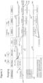
- Figure 2 shows schematically an example embodiment of a method for a key 204 to communicate with an infrastructure (in this example a car 202) to perform a ranging operation. Steps to the left of the vertical dashed line in Figure 2 are associated with the key 204. Steps to the right of the vertical dashed line in Figure 2 are associated with the car 202. As it is shown in Figure 2 , time increases in a vertically down direction.
- the key 204 is shown as having two columns in which method steps can occur.
- the first column relates to ranging operations performed by the key 204, which involves sending and receiving UWB signals in this example.
- UWB signals are shown with dotted lines (as shown in the legend in the top-right corner of the drawing) and also with boxes that are filled with a dotted pattern (as shown in the legend in the bottom-left corner of the drawing).
- the second column relates to communication operations performed by the key 204, which involves sending and receiving BLE signals in this example.
- BLE signals are shown with dashed lines (as shown in the legend in the top-right corner of the drawing).
- the car 202 is shown as having five columns in which method steps can occur.
- the first column relates to communication operations performed by the car 202, which involves sending and receiving BLE signals in this example. Such BLE signals are shown with dashed lines (again as shown in the legend in the top-right corner of the drawing).
- the second column relates to steps that are performed by an electronic control unit (ECU) of the car 202.
- the third to fifth columns relate to ranging operations that are performed by respective first to third ranging antennas associated with the car 202, and involve sending and receiving UWB signals in this example.
- UWB signals are again shown with dotted lines (as shown in the legend in the top-right corner of the drawing) and also with boxes that are filled with a dotted pattern (again as shown in the legend in the bottom-left corner of the drawing).
- a ranging operation is started by the car 202 at step 218.
- the ECU of the car 204 determines timing-information for the subsequent ranging operation.
- the timing-information may comprise an absolute time that the key 204 should send a key-ranging-signal 213 to the car 202 - for instance at 16:10:56 using the 24-hour clock.
- the timing-information may include a key-delay-period (which may also be referred to as a delta-t) that should be waited before the key 204 sends the key-ranging-signal 213 to the car 202.
- the timing-information can be set such that the car 202 has sufficient time to enable its ranging antennas, and also such that the key 204 has sufficient time to receive an instruction from the car 202 and begin transmitting the key-ranging-signal 213 to the car 202.
- the car 202 can then send a ranging-scheduling-signal 210 to the key 204, wherein the ranging-scheduling-signal 210 comprises the timing-information.
- the ranging-scheduling-signal 210 can be provided as part of a periodic car-connection-signal 214 that the car 202 sends to the key 204 to maintain a BLE connection between the car 202 and the key 204.
- the key 204 receives the ranging-scheduling-signal 210 from the car 202 and causes the key 204 to send the key-ranging-signal 213 to the car 202 at a key-ranging-time based on the timing-information.
- this is achieved by a BLE module in the key 204 sending a serial peripheral interface (SPI) message 211 to a UWB module in the key 204.
- SPI message 211 is shown with a dot-dashed line in Figure 2 (as shown in the legend in the top-right corner of the drawing).
- the key-ranging-time may equal the timing-information (i.e. the timing-information is an absolute time).
- the timing-information may comprise a key-delay-period, and the key 204 determines the key-ranging-time by adding the key-delay-period to a clock-signal.
- the key-ranging-time is illustrated schematically in Figure 2 with reference 220, as the instant in time that the key 204 sends the key-ranging-signal 213 to the car 202.
- the key 204 can also send a key-connection-signal 216 to the car 202 to maintain the BLE connection with the car 202.
- the car 202 activates the three ranging antennas that are shown in Figure 2 , at a car-antenna-start-ranging-time based on the timing-information.
- the ranging antennas are represented by the third to fifth columns of the car 202 in Figure 2 , and are for receiving instances of the key-ranging-signal 213 from the key 204.
- the ECU of the car 202 sends an antenna-activation-signal 222 to each of the ranging antennas over a Controller Area Network (CAN) bus.
- the ECU can provide at least some of the functionality of the infrastructure-controller of Figure 1 . Signals sent over the CAN bus are shown as thick lines in Figure 2 (as shown in the legend in the top-right corner of the drawing).
- the antenna-activation-signal 222 instructs each ranging antenna to prepare for ranging (step 224) and then activate the ranging antenna at the car-antenna-start-ranging-time, which is shown schematically in Figure 2 with reference 228.
- the car 202 can set the car-antenna-start-ranging-time 228 such that it equals the timing-information (i.e. the timing-information is an absolute time).
- the car-antenna-start-ranging-time 228 can be set such that it has an absolute time that matches the key-ranging-time 220, or the car-antenna-start-ranging-time 228 can be set such that it has an absolute time that is offset from (and later than) the key-ranging-time 220.
- a time buffer 230 can be provided between the key 204 sending the key-ranging-signal 213 and the ranging antennas being activated for receiving the key-ranging-signal 213.
- the timing-information can include a car-delay-period
- the car 202 can determine the car-antenna-start-ranging-time by adding the car-delay-period to a clock-signal.
- the car-delay-period may the same as, or different to, the key-delay-period.
- the car 202 can deactivate the one or more ranging antennas at a car-antenna-stop-ranging-time 232 (or equivalently an infrastructure-node-stop-ranging-time) based on the timing-information. For instance, the car 202 can determine the car-antenna-stop-ranging-time 232 by adding a predetermined car-antenna-ranging-duration (or equivalently an infrastructure-node-ranging-duration) to the car-antenna-start-ranging-time 228. In other examples, the timing-information comprises the car-antenna-stop-ranging-time 232.
- the length of time that the ranging antenna is activated is represented by the height of the box labelled as 226 in Figure 2 .
- This can also be referred to as a car-antenna-ranging-duration 226, and is the length of time between the car-antenna-start-ranging-time 228 and car-antenna-stop-ranging-time 232.
- At least the car-antenna-start-ranging-time 228 is set based on timing-information that is also used to set the key-ranging-time 220.
- the car 202 responds 234 to the key-ranging-signal 213 by sending a car-response-ranging signal 236 to the key 204.
- the car-response-ranging signal 236 is a UWB signal in this example.
- the car 202 can deactivate the ranging antennas (i.e. the car does not need to wait for a predetermined antenna-stop-ranging-time 232 before deactivating the ranging antennas). Then, in response to sending the car-response-ranging signal 236, the car 202 can reactivate the ranging antennas for receiving a key-response-ranging-signal 238 from the key 204. This reactivation of the ranging antennas is shown schematically in Figure 2 with boxes 240.
- the key 204 waits for the car-response-ranging signal 236 from the car 202 (the waiting is shown schematically as box 242 in Figure 2 ), and when it receives the one or more car-response-ranging signals 236 the key 204 responds with the key-response-ranging-signal 238.
- the key-response-ranging-signal 238 is also a UWB signal in this example. This exchange of UWB signals to complete the ranging operation is well-known in the art.
- the car 202 can determine a ranging result based on: (i) one or more instances of the received key-ranging-signal 213; and (ii) one or more instances of the received key-response-ranging-signal 238.
- the ranging result may be a distance between the key 204 and the car 202, as is known in the art.
- the car can then provide a control-signal (not shown) to an actuator associated with the car based on the ranging result (e.g. to unlock the car).
- Figure 3 shows schematically a method of a key 304 communicating with a car 302 to perform a ranging operation, in which timing-information is not exchanged in order to schedule the ranging operation.
- the length of time 326 that the ranging antenna is activated is much longer than the equivalent duration in Figure 2 .
- the ranging antennas are activated immediately in response to the initiation of the ranging operation. In practice this can result in the ranging antenna being activated for 25 seconds if the key 304 does not come within range of the car 302 to start exchanging UWB signals. For instance, if a user holding their key 204 is close enough to the car 202 for BLE communication to commence, but not close enough for UWB signals to be successfully exchanged, then the car can consume a significant amount of power in listening for UWB signals. In addition to the undesirable power consumption, this can also result in components associated with the ranging antennas overheating.
- Figure 4 shows an example of a timing diagram that illustrates BLE signals that can be sent from a car to schedule ranging operations with a first key and a second key, wherein the ranging operations include exchanging UWB signals.
- the ranging operations with the first key and the second key can be scheduled such that the UWB signals for the individual keys do not clash with each other. It will be appreciated that the functionality that will be described with reference to Figure 4 can be extended to a system that includes more than one second key (and therefore more than two keys in total).
- a BLE connection between the car and the first key (key 1) is shown with reference 450 in Figure 4 .
- This connection has periodic BLE connection events, which include at least a car-connection-signal 414'.
- the BLE connection events occur every 30 ms.
- a BLE connection between the car and the second key (key 2) is shown with reference 452 in Figure 4 .
- This connection also has periodic BLE connection events, which include at least a second-car-connection-signal 414" to maintain a connection with key 2.
- the BLE connection events occur every 60 ms.
- a ranging operation with key 1 is initiated, which causes the BLE connection with key 1 to also include a ranging-scheduling-signal 410'.
- the ranging-scheduling-signal 410' includes timing-information that will be used by key 1 to set a key-ranging-time, at which time key 1 will send a key-ranging-signal to the car.
- the car also uses the timing-information to set a car-antenna-start-ranging-time 428', at which time one or more ranging antennas associated with the car are activated for receiving the key-ranging-signal from key 1 and a ranging round is started.
- a car-delay-period (delta T1) is used to set the car-antenna-start-ranging-time 428'.
- the ranging antenna is scheduled to be activated at the car-antenna-start-ranging-time 428' relative to the ranging-scheduling-signal 414'.
- the ranging rounds for key 1 are shown in Figure 4 as having the car-antenna-start-ranging-time 428', a car-antenna-stop-ranging-time 432' and a car-antenna-ranging-duration 426'.
- the UWB ranging rounds for key 1 are periodic, occurring every 192 ms.
- the car-antenna-ranging-duration 426' is set such that there is sufficient time for a ranging round with multiple anchors / ranging antennas. For instance, there may be 8 anchors / ranging antennas on the car in one example.
- Figure 4 also shows that a ranging operation with key 2 is initiated, which causes the BLE connection with key 2 to also include a second-ranging-scheduling-signal 410".
- the second-ranging-scheduling-signal 410" includes second-timing-information that will be used by key 2 to set a second key-ranging-time, at which time key 2 will send a second-key-ranging-signal to the car.
- the car also uses the second-timing-information to set a second-car-antenna-start-ranging-time 428", at which time the one or more ranging antennas associated with the car are activated for receiving the second-key-ranging-signal from key 2 and a ranging round is started.
- a second-car-delay-period (delta T2) is used to set the second-car-antenna-start-ranging-time 428".
- the ranging antenna is scheduled to be activated at the second car-antenna-start-ranging-time 428" relative to the second-ranging-scheduling-signal 414".
- the ranging rounds for key 2 are shown in Figure 4 as having the second-car-antenna-start-ranging-time 428", a second-car-antenna-stop-ranging-time 432" and a car-antenna-ranging-duration 426".
- the UWB ranging rounds for key 2 are also periodic, occurring every 192 ms.
- the car for example a car-controller associated with the car
- the car can set the second-car-antenna-start-ranging-time such that the ranging antennas are activated for the second key at a time that does not overlap with when the ranging antennas are activated for the first key. In this way, the likelihood of any clashes between the ranging operations can be reduced or avoided.
- a car-controller associated with the car can negotiate delta T1 and delta T2 using BLE signals (i.e. out-of-band signals when compared with the UWB ranging signals) before any UWB ranging signals are exchanged.
- BLE signals i.e. out-of-band signals when compared with the UWB ranging signals
- a car-controller can set one or more of: a car-antenna-start-ranging-time, a car-antenna-stop-ranging-time, a car-antenna-ranging-duration, a second-car-antenna-start-ranging-time, a second-car-antenna-stop-ranging-time and a car-antenna-ranging-duration; such that the ranging antennas are activated for the second key at a time that does not overlap with when the ranging antennas are activated for the first key and any other second keys if there are any.
- One or more of the examples disclosed herein propose as a first step (one portable device is doing the ranging service) that via a connectivity radio a payload is sent out in order to propose a time value, which can be a delay between the out of band connectivity radio packet and the time when a portable device will send out its first ranging radio packet. This delay can be matched to the internal capabilities of the infrastructure and the delays in this distributed network.
- a car there can be several BLE anchors connected via CAN to a central microcontroller.
- This microcontroller can control distributed UWB anchors via the same CAN bus or over different gateways.
- the car can have access to predetermined values for the internal delays that occur when switching on the UWB receivers, and on this basis it can send out a proposed time window for the portable device (all of that relative to a radio connection event on the air (e.g. a BLE connection between car and key)).
- this portable device may not be synchronized at all to the other portable device.
- the infrastructure / car can have access to the timings of the communications between the two portable devices. Examples disclosed herein can schedule the second portable device relative to the first running ranging service with the first portable device. E.g. because the car knows the connectivity to portable device 1 and 2. An example disclosed herein can propose another slot (by sending out another delay to the portable device 2). In this way, the different ranging sessions (session 1 and 2) are scheduled to avoid collisions. If a third device is found and connected, then this procedure can of course be extended such that the ranging sessions of all three devices do not collide.
- Examples disclosed herein can be especially useful in a car access system.
- This includes a car access system with many UWB receivers for localisation and BLE nodes for communication, and several authorized keys that can legitimately approach the car (this can be considered as a private fleet).
- Communication can start with low power BLE radio and after some time UWB ranging starts for localisation.
- the car first enables its own UWB receivers and then requests the key device to initiate ranging.
- the car should enable UWB receivers early enough in order not to miss incoming UWB messages.
- the receive windows should be large enough since BLE communication delay and uncertainty may not be known - for instance they can variable based on the environment. However, advantageously this window can be reduced or minimized by executing both initiate and respond commands at known synchronized times. Thus, saving power on UWB nodes which are waiting for the incoming initiation message.
- the car does not a priori need to know which of a plurality of keys is the preferred key and has to try (range) all devices that are detected.
- This method can avoid unnecessary collisions with a retry method (hopping sequence) that is currently proposed by the Car Connectivity Consortium (CCC) because it can actively schedule the ranging activities leading to a defined and optimized system performance.
- CCC Car Connectivity Consortium
- examples disclosed herein can relate to active scheduling instead of hopping in time slots when collisions are detected.
- the scheduling can relate to scheduling ranging rounds to various keys / devices / tags.
- the set of instructions/method steps described above are implemented as functional and software instructions embodied as a set of executable instructions which are effected on a computer or machine which is programmed with and controlled by said executable instructions. Such instructions are loaded for execution on a processor (such as one or more CPUs).
- processor includes microprocessors, microcontrollers, processor modules or subsystems (including one or more microprocessors or microcontrollers), or other control or computing devices.
- a processor can refer to a single component or to plural components.
- the set of instructions/methods illustrated herein and data and instructions associated therewith are stored in respective storage devices, which are implemented as one or more non-transient machine or computer-readable or computer-usable storage media or mediums.
- Such computer-readable or computer usable storage medium or media is (are) considered to be part of an article (or article of manufacture).
- An article or article of manufacture can refer to any manufactured single component or multiple components.
- the non-transient machine or computer usable media or mediums as defined herein excludes signals, but such media or mediums may be capable of receiving and processing information from signals and/or other transient mediums.
- Example embodiments of the material discussed in this specification can be implemented in whole or in part through network, computer, or data based devices and/or services. These may include cloud, internet, intranet, mobile, desktop, processor, look-up table, microcontroller, consumer equipment, infrastructure, or other enabling devices and services. As may be used herein and in the claims, the following non-exclusive definitions are provided.
- one or more instructions or steps discussed herein are automated.
- the terms automated or automatically mean controlled operation of an apparatus, system, and/or process using computers and/or mechanical/electrical devices without the necessity of human intervention, observation, effort and/or decision.
- any components said to be coupled may be coupled or connected either directly or indirectly.
- additional components may be located between the two components that are said to be coupled.
Landscapes
- Engineering & Computer Science (AREA)
- Physics & Mathematics (AREA)
- General Physics & Mathematics (AREA)
- Computer Networks & Wireless Communication (AREA)
- Signal Processing (AREA)
- Theoretical Computer Science (AREA)
- General Engineering & Computer Science (AREA)
- Computer Hardware Design (AREA)
- Computing Systems (AREA)
- Lock And Its Accessories (AREA)
- Mobile Radio Communication Systems (AREA)
Claims (15)
- Infrastruktursteuereinheit (106) für eine Infrastruktur (102), wobei die Infrastruktursteuereinheit konfiguriert ist zum:Senden eines Bereichsplanungssignals (110) zu einem Schlüssel (104), wobei das Bereichsplanungssignal Zeitplaninformationen für eine nachfolgende Bereichsoperation umfasst; undAktivieren eines oder mehrerer Bereichsknoten (112), die mit der Infrastruktur assoziiert sind, zum Empfangen eines Schlüsselbereichssignals (113) von dem Schlüssel zu einem Zeitpunkt eines Startbereichs eines Infrastrukturknotens basierend auf den Zeitplaninformationen;wobei:wobei das Bereichsplanungssignal eine Frequenz in einem ersten HF-Frequenzbereich aufweist;wobei das Schlüsselbereichssignal eine Frequenz in einem zweiten HF-Frequenzbereich aufweist; undwobei der zweite HF-Frequenzbereich verschieden von dem ersten HF-Frequenzbereich ist.
- Infrastruktursteuereinheit nach Anspruch 1, wobei:das Bereichsplanungssignal ein BLE-Signal ist; unddas Schlüsselbereichssignal ein UWB-Signal ist.
- Infrastruktursteuereinheit nach Anspruch 1 oder Anspruch 2, wobei die Infrastruktursteuereinheit für jeden von einem oder mehreren zweiten Schlüsseln ferner konfiguriert ist zum:Senden eines zweiten Bereichsplanungssignals (410") zu dem zweiten Schlüssel, wobei das zweite Bereichsplanungssignal zweite Zeitplaninformationen für eine nachfolgende Bereichsoperation umfasst; undAktivieren des einen oder der mehreren Bereichsknoten, die mit der Infrastruktur assoziiert sind, zum Empfangen eines zweiten Schlüsselbereichssignals von dem zweiten Schlüssel zu einem zweiten Zeitpunkt eines Startbereichs eines Infrastrukturknotens basierend auf den zweiten Zeitplaninformationen;wobei:der zweite Zeitpunkt eines Startbereichs eines Infrastrukturknotens so eingestellt ist, dass die Bereichsknoten für den zweiten Schlüssel zu einem Zeitpunkt aktiviert werden, der sich nicht damit überschneidet, wenn die Bereichsknoten für den ersten Schlüssel und beliebige andere zweite Schlüssel, falls vorhanden, aktiviert sind;wobei das zweite Bereichsplanungssignal eine Frequenz in dem ersten HF-Frequenzbereich aufweist; undwobei das zweite Schlüsselbereichssignal eine Frequenz in dem zweiten HF-Frequenzbereich aufweist.
- Infrastruktursteuereinheit nach Anspruch 3, wobei die Infrastruktursteuereinheit konfiguriert ist zum Einstellen eines oder mehrerer von: einem Zeitpunkt eines Startbereichs eines Infrastrukturknotens; einem Zeitpunkt eines Stoppbereichs eines Infrastrukturknotens, einer Bereichsdauer des Infrastrukturknotens, einem zweiten Zeitpunkt eines Startbereichs eines Infrastrukturknotens, einem zweiten Zeitpunkt eines Stoppbereichs eines Infrastrukturknotens und einer zweiten Bereichsdauer des Infrastrukturknotens, sodass die Bereichsknoten für den einen oder die mehreren zweiten Schlüssel zu einem Zeitpunkt aktiviert werden, der sich nicht damit überschneidet, wenn die Bereichsknoten für den ersten Schlüssel und beliebige andere zweite Schlüssel, falls vorhanden, aktiviert sind.
- Infrastruktursteuereinheit nach einem der vorhergehenden Ansprüche, wobei die Infrastruktursteuereinheit konfiguriert ist zum:
Aktivieren des einen oder der mehreren Bereichsknoten, die mit der Infrastruktur assoziiert sind, indem ein Knotenaktivierungssignal (222) über einen CAN-Bus, "Controller Area Network" Bus, zu dem einen oder den mehreren Bereichsknoten gesendet werden. - Infrastruktursteuereinheit nach einem der vorhergehenden Ansprüche, wobei der Zeitpunkt eines Startbereichs eines Infrastrukturknotens gleich den Zeitplaninformationen ist.
- Infrastruktursteuereinheit nach einem der Ansprüche 1 bis 5, wobei:die Zeitplaninformationen eine Infrastrukturverzögerungsperiode umfassen; unddie Infrastruktursteuereinheit konfiguriert ist zum Ermitteln des Zeitpunkts eines Startbereichs eines Infrastrukturknotens, indem die Infrastrukturverzögerungsperiode zu einem Taktsignal addiert wird.
- Infrastruktursteuereinheit nach einem der vorhergehenden Ansprüche, wobei die Infrastruktur ein Fahrzeug oder ein Gebäude ist.
- Infrastruktursteuereinheit nach einem der vorhergehenden Ansprüche, wobei:die Infrastruktursteuereinheit konfiguriert ist zum Senden eines Infrastrukturverbindungssignals (114) zu dem Schlüssel, um eine Verbindung mit dem Schlüssel aufrechtzuerhalten; unddas Infrastrukturverbindungssignal eine Frequenz in dem ersten HF-Frequenzbereich aufweist.
- Infrastruktursteuereinheit nach einem der vorhergehenden Ansprüche, wobei die Infrastruktursteuereinheit ferner konfiguriert ist zum:
Ermitteln eines Bereichsergebnisses basierend auf dem empfangenen Schlüsselbereichssignal. - Infrastruktursteuereinheit nach einem der vorhergehenden Ansprüche, wobei die Infrastruktursteuereinheit konfiguriert ist zum:Aktivieren einer Vielzahl von Bereichsknoten, die mit der Infrastruktur assoziiert sind, um eine Vielzahl von Instanzen des Schlüsselbereichssignals von dem Schlüssel zu empfangen;Aktivieren der Vielzahl von Bereichsknoten, die mit der Infrastruktur assoziiert sind, um eine Vielzahl von Instanzen des Schlüsselantwortbereichssignals von dem Schlüssel zu empfangen; undErmitteln des Bereichsergebnisses basierend auf: einer oder mehreren der Vielzahl von Instanzen des empfangenen Schlüsselbereichssignals und einer oder mehreren der Vielzahl von Instanzen des empfangenen Schlüsselantwortbereichssignals.
- Infrastruktursteuereinheit nach Anspruch 11, wobei die Infrastruktursteuereinheit konfiguriert ist zum:
Bereitstellen, basierend auf dem Bereichsergebnis, eines Steuersignals für ein Stellglied, das mit der Infrastruktur assoziiert ist. - Schlüsselsteuereinheit (108), die konfiguriert ist zum:Empfangen eines Bereichsplanungssignals (110) von einer Infrastruktur (102), wobei das Bereichsplanungssignal Zeitplaninformationen für eine nachfolgende Bereichsoperation umfasst; undVeranlassen eines Schlüssels (104) zum Senden eines Schlüsselbereichssignals (113) zu der Infrastruktur zu einem Schlüsselbereichszeitpunkt basierend auf den Zeitplaninformationen;wobei:wobei das Bereichsplanungssignal eine Frequenz in einem ersten HF-Frequenzbereich aufweist;das Schlüsselbereichssignal in einem zweiten HF-Frequenzbereich liegt; undwobei der zweite HF-Frequenzbereich verschieden von dem ersten HF-Frequenzbereich ist.
- Computerimplementiertes Verfahren für eine Infrastruktur (102), wobei das Verfahren umfasst:Senden eines Bereichsplanungssignals (110) zu einem Schlüssel (104), wobei das Bereichsplanungssignal Zeitplaninformationen für eine nachfolgende Bereichsoperation umfasst; undAktivieren eines oder mehrerer Bereichsknoten (112), die mit der Infrastruktur assoziiert sind, zum Empfangen eines Schlüsselbereichssignals (113) von dem Schlüssel zu einem Zeitpunkt eines Startbereichs eines Infrastrukturknotens basierend auf den Zeitplaninformationen;wobei:wobei das Bereichsplanungssignal eine Frequenz in einem ersten HF-Frequenzbereich aufweist;das Schlüsselbereichssignal in einem zweiten HF-Frequenzbereich liegt; undwobei der zweite HF-Frequenzbereich verschieden von dem ersten HF-Frequenzbereich ist.
- Computerimplementiertes Verfahren für einen Schlüssel (104), wobei das Verfahren umfasst:Empfangen eines Bereichsplanungssignals (110) von einer Infrastruktur (102), wobei das Bereichsplanungssignal Zeitplaninformationen für eine nachfolgende Bereichsoperation umfasst; undVeranlassen eines Schlüssels zum Senden eines Schlüsselbereichssignals (113) zu der Infrastruktur zu einem Schlüsselbereichszeitpunkt basierend auf den Zeitplaninformationen;wobei:wobei das Bereichsplanungssignal eine Frequenz in einem ersten HF-Frequenzbereich aufweist;das Schlüsselbereichssignal in einem zweiten HF-Frequenzbereich liegt; undwobei der zweite HF-Frequenzbereich verschieden von dem ersten HF-Frequenzbereich ist.
Priority Applications (3)
| Application Number | Priority Date | Filing Date | Title |
|---|---|---|---|
| EP20215052.0A EP4016247B1 (de) | 2020-12-17 | 2020-12-17 | Infrastruktursteuerung für eine infrastruktur und schlüsselsteuerung für einen schlüssel |
| US17/504,767 US11875619B2 (en) | 2020-12-17 | 2021-10-19 | Infrastructure controller for an infrastructure and a key controller for a key |
| CN202111337550.9A CN114650506A (zh) | 2020-12-17 | 2021-11-10 | 用于基础设施的基础设施控制器和用于钥匙的钥匙控制器 |
Applications Claiming Priority (1)
| Application Number | Priority Date | Filing Date | Title |
|---|---|---|---|
| EP20215052.0A EP4016247B1 (de) | 2020-12-17 | 2020-12-17 | Infrastruktursteuerung für eine infrastruktur und schlüsselsteuerung für einen schlüssel |
Publications (2)
| Publication Number | Publication Date |
|---|---|
| EP4016247A1 EP4016247A1 (de) | 2022-06-22 |
| EP4016247B1 true EP4016247B1 (de) | 2025-06-18 |
Family
ID=73855368
Family Applications (1)
| Application Number | Title | Priority Date | Filing Date |
|---|---|---|---|
| EP20215052.0A Active EP4016247B1 (de) | 2020-12-17 | 2020-12-17 | Infrastruktursteuerung für eine infrastruktur und schlüsselsteuerung für einen schlüssel |
Country Status (3)
| Country | Link |
|---|---|
| US (1) | US11875619B2 (de) |
| EP (1) | EP4016247B1 (de) |
| CN (1) | CN114650506A (de) |
Families Citing this family (4)
| Publication number | Priority date | Publication date | Assignee | Title |
|---|---|---|---|---|
| JP7639366B2 (ja) * | 2021-01-28 | 2025-03-05 | 株式会社デンソー | 電子キーシステム |
| DE102023206058A1 (de) * | 2023-06-27 | 2025-01-02 | Continental Automotive Technologies GmbH | Verfahren und Vorrichtungen zur Kontrolle des Zugangs zu einem Fahrzeug; Zeitlich konfigurierbares Relay Attack Defense System |
| CN120282110A (zh) * | 2024-01-05 | 2025-07-08 | 蔚来移动科技有限公司 | Uwb数字钥匙的通信碰撞处理方法、设备、钥匙及介质 |
| FR3165139A1 (fr) * | 2024-07-23 | 2026-01-30 | Valeo Comfort And Driving Assistance | Planification de localisations UWB avec décalage |
Family Cites Families (20)
| Publication number | Priority date | Publication date | Assignee | Title |
|---|---|---|---|---|
| US9747736B2 (en) * | 2014-08-05 | 2017-08-29 | Texas Instruments Deutschland Gmbh | Multiple-band identification and ranging |
| US9775034B2 (en) * | 2015-02-06 | 2017-09-26 | Nxp B.V. | Communications with distance authentication |
| JP6814752B2 (ja) | 2015-03-07 | 2021-01-20 | ベリティ ストゥディオス アーゲー | 分散された位置特定システムおよび方法ならびに自己位置特定装置 |
| US10111044B2 (en) | 2015-05-29 | 2018-10-23 | Verity Studios Ag | Methods and systems for scheduling the transmission of localization signals and operating self-localizing apparatus |
| CN107923963B (zh) | 2015-05-29 | 2022-04-19 | 维里蒂工作室股份公司 | 用于调度定位信号传输和操作自定位装置的方法和系统 |
| US9967722B2 (en) | 2016-06-29 | 2018-05-08 | Silicon Laboratories Finland Oy | Packet transmission timing parameter discovery for wireless communication synchronization |
| CN106028272B (zh) | 2016-07-25 | 2019-06-14 | 广东乐心医疗电子股份有限公司 | 基于分布式ble通信协议无线传感系统时间同步方法与装置 |
| EP3335942B1 (de) * | 2016-12-14 | 2019-11-20 | Nxp B.V. | Sicheres ventilzugangssystem für fahrzeug, schlüssel, fahrzeug und verfahren dafür |
| US10486646B2 (en) * | 2017-09-29 | 2019-11-26 | Apple Inc. | Mobile device for communicating and ranging with access control system for automatic functionality |
| US10861327B2 (en) * | 2018-01-12 | 2020-12-08 | Qualcomm Incorporated | Vehicle ranging and positioning |
| KR102060172B1 (ko) | 2018-02-08 | 2020-01-21 | (주)라이즈넷 | 시간 동기화 무선 통신에서의 무선 멀티홉 네트워크 시스템 |
| KR102104104B1 (ko) | 2018-02-08 | 2020-04-28 | (주)라이즈넷 | 시간 동기화 무선 통신에서의 무선 멀티홉 네트워크 스케쥴링 관리 방법 |
| US10555119B2 (en) | 2018-07-06 | 2020-02-04 | Apple Inc. | Ranging priority indication |
| US10652925B2 (en) * | 2018-09-25 | 2020-05-12 | Apple Inc. | Medium access control and channel access for access operations |
| KR102564520B1 (ko) * | 2018-09-28 | 2023-08-08 | 애플 인크. | 모바일 디바이스들 사이의 레인징 |
| EP3841829B1 (de) * | 2018-12-07 | 2025-11-05 | Samsung Electronics Co., Ltd. | Verfahren und vorrichtung zum senden und empfangen von daten über uwb in einem drahtloskommunikationssystem |
| JP7210382B2 (ja) * | 2019-06-05 | 2023-01-23 | アルパイン株式会社 | 車両制御システム |
| US11427157B2 (en) * | 2019-06-07 | 2022-08-30 | Continental Automotive Systems, Inc. | Low frequency or ultra wide band control by BLE in identification device |
| US11052851B1 (en) * | 2020-03-24 | 2021-07-06 | Kiomars Anvari | Use of IoT network and IoT ranging device for a navigation and protection system |
| US11230260B2 (en) * | 2020-06-26 | 2022-01-25 | Denso International America, Inc. | Adaptive BLE and UWB based connection rate control for mobile access devices of vehicular passive access systems |
-
2020
- 2020-12-17 EP EP20215052.0A patent/EP4016247B1/de active Active
-
2021
- 2021-10-19 US US17/504,767 patent/US11875619B2/en active Active
- 2021-11-10 CN CN202111337550.9A patent/CN114650506A/zh active Pending
Also Published As
| Publication number | Publication date |
|---|---|
| US20220198850A1 (en) | 2022-06-23 |
| EP4016247A1 (de) | 2022-06-22 |
| US11875619B2 (en) | 2024-01-16 |
| CN114650506A (zh) | 2022-06-21 |
Similar Documents
| Publication | Publication Date | Title |
|---|---|---|
| US11875619B2 (en) | Infrastructure controller for an infrastructure and a key controller for a key | |
| US11671918B2 (en) | Implementation of traffic coexistence for collocated transceivers including Bluetooth transceivers | |
| TWI444069B (zh) | 通訊裝置與多層次傳輸功率控制方法 | |
| JP2024026068A (ja) | 自動機能のためにアクセス制御システムと通信及び測距を行うモバイルデバイス | |
| US20120322481A1 (en) | Band steering | |
| US20180332565A1 (en) | Wireless communication device, wireless communication system, wireless communication method and program | |
| KR20060007009A (ko) | 무선통신 시스템, 무선통신장치 및 무선통신방법과컴퓨터·프로그램 | |
| CN101426279A (zh) | 处理随机存取程序失败的方法及其相关通讯装置 | |
| CN109639692B (zh) | 离线登录的方法、装置、设备、系统和存储介质 | |
| EP2823675A1 (de) | Energiesparmechanismus für peer-to-peer-kommunikationsnetzwerke | |
| CN103959678A (zh) | 无线网络中的无线电装置共存 | |
| US20040142690A1 (en) | Wireless communication system and a hand-off method therefor | |
| CN106341899A (zh) | 基于非授权载波执行随机接入的方法及装置 | |
| US12513635B2 (en) | Data transmission method and related device | |
| WO2023025157A1 (zh) | 对讲中继系统及其射频收发控制方法、装置 | |
| CN107079488A (zh) | 一种随机接入方法及装置 | |
| CN115665888A (zh) | 建立蓝牙连接的方法、存储介质、芯片、耳机及设备系统 | |
| US11039457B2 (en) | Traffic coexistence for collocated transceivers including bluetooth transceivers | |
| JP2009055350A (ja) | 無線通信システム及び方法 | |
| WO2012122906A1 (zh) | 一种信道占用方法、移动ap和外接sta | |
| US8396422B2 (en) | Communication control device, method of determining communication control device, and storage medium for performing the method | |
| US20160081015A1 (en) | Wireless communication device and wireless communication control method | |
| WO2020078407A1 (zh) | Drx的配置方法及装置 | |
| US20250081238A1 (en) | Managing coexistence of communication protocols in user device | |
| CN111867122B (zh) | 随机接入方法、网络侧节点及终端 |
Legal Events
| Date | Code | Title | Description |
|---|---|---|---|
| PUAI | Public reference made under article 153(3) epc to a published international application that has entered the european phase |
Free format text: ORIGINAL CODE: 0009012 |
|
| STAA | Information on the status of an ep patent application or granted ep patent |
Free format text: STATUS: THE APPLICATION HAS BEEN PUBLISHED |
|
| AK | Designated contracting states |
Kind code of ref document: A1 Designated state(s): AL AT BE BG CH CY CZ DE DK EE ES FI FR GB GR HR HU IE IS IT LI LT LU LV MC MK MT NL NO PL PT RO RS SE SI SK SM TR |
|
| STAA | Information on the status of an ep patent application or granted ep patent |
Free format text: STATUS: REQUEST FOR EXAMINATION WAS MADE |
|
| 17P | Request for examination filed |
Effective date: 20221222 |
|
| RBV | Designated contracting states (corrected) |
Designated state(s): AL AT BE BG CH CY CZ DE DK EE ES FI FR GB GR HR HU IE IS IT LI LT LU LV MC MK MT NL NO PL PT RO RS SE SI SK SM TR |
|
| REG | Reference to a national code |
Ref country code: DE Ref legal event code: R079 Ipc: G06F0001320900 Ref document number: 602020052872 Country of ref document: DE Free format text: PREVIOUS MAIN CLASS: G06F0001320000 |
|
| RIC1 | Information provided on ipc code assigned before grant |
Ipc: G06F 1/3287 20190101ALI20250211BHEP Ipc: G06F 1/3209 20190101AFI20250211BHEP |
|
| GRAP | Despatch of communication of intention to grant a patent |
Free format text: ORIGINAL CODE: EPIDOSNIGR1 |
|
| STAA | Information on the status of an ep patent application or granted ep patent |
Free format text: STATUS: GRANT OF PATENT IS INTENDED |
|
| INTG | Intention to grant announced |
Effective date: 20250403 |
|
| GRAS | Grant fee paid |
Free format text: ORIGINAL CODE: EPIDOSNIGR3 |
|
| GRAA | (expected) grant |
Free format text: ORIGINAL CODE: 0009210 |
|
| STAA | Information on the status of an ep patent application or granted ep patent |
Free format text: STATUS: THE PATENT HAS BEEN GRANTED |
|
| AK | Designated contracting states |
Kind code of ref document: B1 Designated state(s): AL AT BE BG CH CY CZ DE DK EE ES FI FR GB GR HR HU IE IS IT LI LT LU LV MC MK MT NL NO PL PT RO RS SE SI SK SM TR |
|
| REG | Reference to a national code |
Ref country code: GB Ref legal event code: FG4D |
|
| REG | Reference to a national code |
Ref country code: CH Ref legal event code: EP |
|
| REG | Reference to a national code |
Ref country code: DE Ref legal event code: R096 Ref document number: 602020052872 Country of ref document: DE |
|
| REG | Reference to a national code |
Ref country code: CH Ref legal event code: EP |
|
| REG | Reference to a national code |
Ref country code: IE Ref legal event code: FG4D |
|
| PG25 | Lapsed in a contracting state [announced via postgrant information from national office to epo] |
Ref country code: FI Free format text: LAPSE BECAUSE OF FAILURE TO SUBMIT A TRANSLATION OF THE DESCRIPTION OR TO PAY THE FEE WITHIN THE PRESCRIBED TIME-LIMIT Effective date: 20250618 |
|
| REG | Reference to a national code |
Ref country code: LT Ref legal event code: MG9D |
|
| PG25 | Lapsed in a contracting state [announced via postgrant information from national office to epo] |
Ref country code: GR Free format text: LAPSE BECAUSE OF FAILURE TO SUBMIT A TRANSLATION OF THE DESCRIPTION OR TO PAY THE FEE WITHIN THE PRESCRIBED TIME-LIMIT Effective date: 20250919 Ref country code: NO Free format text: LAPSE BECAUSE OF FAILURE TO SUBMIT A TRANSLATION OF THE DESCRIPTION OR TO PAY THE FEE WITHIN THE PRESCRIBED TIME-LIMIT Effective date: 20250918 |
|
| PG25 | Lapsed in a contracting state [announced via postgrant information from national office to epo] |
Ref country code: BG Free format text: LAPSE BECAUSE OF FAILURE TO SUBMIT A TRANSLATION OF THE DESCRIPTION OR TO PAY THE FEE WITHIN THE PRESCRIBED TIME-LIMIT Effective date: 20250618 |
|
| PG25 | Lapsed in a contracting state [announced via postgrant information from national office to epo] |
Ref country code: HR Free format text: LAPSE BECAUSE OF FAILURE TO SUBMIT A TRANSLATION OF THE DESCRIPTION OR TO PAY THE FEE WITHIN THE PRESCRIBED TIME-LIMIT Effective date: 20250618 |
|
| PG25 | Lapsed in a contracting state [announced via postgrant information from national office to epo] |
Ref country code: RS Free format text: LAPSE BECAUSE OF FAILURE TO SUBMIT A TRANSLATION OF THE DESCRIPTION OR TO PAY THE FEE WITHIN THE PRESCRIBED TIME-LIMIT Effective date: 20250918 |
|
| REG | Reference to a national code |
Ref country code: NL Ref legal event code: MP Effective date: 20250618 |
|
| PG25 | Lapsed in a contracting state [announced via postgrant information from national office to epo] |
Ref country code: LV Free format text: LAPSE BECAUSE OF FAILURE TO SUBMIT A TRANSLATION OF THE DESCRIPTION OR TO PAY THE FEE WITHIN THE PRESCRIBED TIME-LIMIT Effective date: 20250618 |
|
| PG25 | Lapsed in a contracting state [announced via postgrant information from national office to epo] |
Ref country code: NL Free format text: LAPSE BECAUSE OF FAILURE TO SUBMIT A TRANSLATION OF THE DESCRIPTION OR TO PAY THE FEE WITHIN THE PRESCRIBED TIME-LIMIT Effective date: 20250618 |
|
| PG25 | Lapsed in a contracting state [announced via postgrant information from national office to epo] |
Ref country code: PT Free format text: LAPSE BECAUSE OF FAILURE TO SUBMIT A TRANSLATION OF THE DESCRIPTION OR TO PAY THE FEE WITHIN THE PRESCRIBED TIME-LIMIT Effective date: 20251020 |
|
| REG | Reference to a national code |
Ref country code: AT Ref legal event code: MK05 Ref document number: 1804796 Country of ref document: AT Kind code of ref document: T Effective date: 20250618 |
|
| PG25 | Lapsed in a contracting state [announced via postgrant information from national office to epo] |
Ref country code: IS Free format text: LAPSE BECAUSE OF FAILURE TO SUBMIT A TRANSLATION OF THE DESCRIPTION OR TO PAY THE FEE WITHIN THE PRESCRIBED TIME-LIMIT Effective date: 20251018 |
|
| PGFP | Annual fee paid to national office [announced via postgrant information from national office to epo] |
Ref country code: DE Payment date: 20251126 Year of fee payment: 6 |
|
| PG25 | Lapsed in a contracting state [announced via postgrant information from national office to epo] |
Ref country code: AT Free format text: LAPSE BECAUSE OF FAILURE TO SUBMIT A TRANSLATION OF THE DESCRIPTION OR TO PAY THE FEE WITHIN THE PRESCRIBED TIME-LIMIT Effective date: 20250618 Ref country code: SM Free format text: LAPSE BECAUSE OF FAILURE TO SUBMIT A TRANSLATION OF THE DESCRIPTION OR TO PAY THE FEE WITHIN THE PRESCRIBED TIME-LIMIT Effective date: 20250618 |
|
| PGFP | Annual fee paid to national office [announced via postgrant information from national office to epo] |
Ref country code: FR Payment date: 20251120 Year of fee payment: 6 |
|
| PG25 | Lapsed in a contracting state [announced via postgrant information from national office to epo] |
Ref country code: CZ Free format text: LAPSE BECAUSE OF FAILURE TO SUBMIT A TRANSLATION OF THE DESCRIPTION OR TO PAY THE FEE WITHIN THE PRESCRIBED TIME-LIMIT Effective date: 20250618 |
|
| PG25 | Lapsed in a contracting state [announced via postgrant information from national office to epo] |
Ref country code: PL Free format text: LAPSE BECAUSE OF FAILURE TO SUBMIT A TRANSLATION OF THE DESCRIPTION OR TO PAY THE FEE WITHIN THE PRESCRIBED TIME-LIMIT Effective date: 20250618 |
|
| PG25 | Lapsed in a contracting state [announced via postgrant information from national office to epo] |
Ref country code: EE Free format text: LAPSE BECAUSE OF FAILURE TO SUBMIT A TRANSLATION OF THE DESCRIPTION OR TO PAY THE FEE WITHIN THE PRESCRIBED TIME-LIMIT Effective date: 20250618 |
|
| PG25 | Lapsed in a contracting state [announced via postgrant information from national office to epo] |
Ref country code: RO Free format text: LAPSE BECAUSE OF FAILURE TO SUBMIT A TRANSLATION OF THE DESCRIPTION OR TO PAY THE FEE WITHIN THE PRESCRIBED TIME-LIMIT Effective date: 20250618 Ref country code: SK Free format text: LAPSE BECAUSE OF FAILURE TO SUBMIT A TRANSLATION OF THE DESCRIPTION OR TO PAY THE FEE WITHIN THE PRESCRIBED TIME-LIMIT Effective date: 20250618 |
|
| PG25 | Lapsed in a contracting state [announced via postgrant information from national office to epo] |
Ref country code: ES Free format text: LAPSE BECAUSE OF FAILURE TO SUBMIT A TRANSLATION OF THE DESCRIPTION OR TO PAY THE FEE WITHIN THE PRESCRIBED TIME-LIMIT Effective date: 20250618 |
|
| REG | Reference to a national code |
Ref country code: DE Ref legal event code: R097 Ref document number: 602020052872 Country of ref document: DE |
|
| PG25 | Lapsed in a contracting state [announced via postgrant information from national office to epo] |
Ref country code: DK Free format text: LAPSE BECAUSE OF FAILURE TO SUBMIT A TRANSLATION OF THE DESCRIPTION OR TO PAY THE FEE WITHIN THE PRESCRIBED TIME-LIMIT Effective date: 20250618 |
|
| PG25 | Lapsed in a contracting state [announced via postgrant information from national office to epo] |
Ref country code: IT Free format text: LAPSE BECAUSE OF FAILURE TO SUBMIT A TRANSLATION OF THE DESCRIPTION OR TO PAY THE FEE WITHIN THE PRESCRIBED TIME-LIMIT Effective date: 20250618 |
|
| PLBE | No opposition filed within time limit |
Free format text: ORIGINAL CODE: 0009261 |
|
| STAA | Information on the status of an ep patent application or granted ep patent |
Free format text: STATUS: NO OPPOSITION FILED WITHIN TIME LIMIT |
|
| REG | Reference to a national code |
Ref country code: CH Ref legal event code: L10 Free format text: ST27 STATUS EVENT CODE: U-0-0-L10-L00 (AS PROVIDED BY THE NATIONAL OFFICE) Effective date: 20260430 |