EP4018799A1 - Procédé de dépôt des portions de granulé sur un terrain agricole au moyen d'une machine d'épandage agricole - Google Patents
Procédé de dépôt des portions de granulé sur un terrain agricole au moyen d'une machine d'épandage agricole Download PDFInfo
- Publication number
- EP4018799A1 EP4018799A1 EP21212409.3A EP21212409A EP4018799A1 EP 4018799 A1 EP4018799 A1 EP 4018799A1 EP 21212409 A EP21212409 A EP 21212409A EP 4018799 A1 EP4018799 A1 EP 4018799A1
- Authority
- EP
- European Patent Office
- Prior art keywords
- granulate
- furrow
- deposit
- agricultural
- furrow opener
- Prior art date
- Legal status (The legal status is an assumption and is not a legal conclusion. Google has not performed a legal analysis and makes no representation as to the accuracy of the status listed.)
- Withdrawn
Links
Images







Classifications
-
- A—HUMAN NECESSITIES
- A01—AGRICULTURE; FORESTRY; ANIMAL HUSBANDRY; HUNTING; TRAPPING; FISHING
- A01C—PLANTING; SOWING; FERTILISING
- A01C5/00—Making or covering furrows or holes for sowing, planting or manuring
- A01C5/06—Machines for making or covering drills or furrows for sowing or planting
- A01C5/062—Devices for making drills or furrows
- A01C5/064—Devices for making drills or furrows with rotating tools
-
- A—HUMAN NECESSITIES
- A01—AGRICULTURE; FORESTRY; ANIMAL HUSBANDRY; HUNTING; TRAPPING; FISHING
- A01C—PLANTING; SOWING; FERTILISING
- A01C7/00—Sowing
- A01C7/06—Seeders combined with fertilising apparatus
-
- A—HUMAN NECESSITIES
- A01—AGRICULTURE; FORESTRY; ANIMAL HUSBANDRY; HUNTING; TRAPPING; FISHING
- A01C—PLANTING; SOWING; FERTILISING
- A01C5/00—Making or covering furrows or holes for sowing, planting or manuring
- A01C5/06—Machines for making or covering drills or furrows for sowing or planting
- A01C5/066—Devices for covering drills or furrows
- A01C5/068—Furrow packing devices, e.g. press wheels
-
- A—HUMAN NECESSITIES
- A01—AGRICULTURE; FORESTRY; ANIMAL HUSBANDRY; HUNTING; TRAPPING; FISHING
- A01C—PLANTING; SOWING; FERTILISING
- A01C7/00—Sowing
- A01C7/20—Parts of seeders for conducting and depositing seed
Definitions
- the invention relates to a method for depositing granulate portions on an agricultural area by means of an agricultural spreading machine according to the preamble of patent claim 1 and a device for depositing granulate portions on an agricultural area according to the preamble of patent claim 14.
- granules In a large number of applications, it is advantageous or even necessary for granules to be placed on an agricultural area in the form of portions.
- These granulate portions can be fertilizer portions, for example, in the vicinity of which a single seed grain is placed.
- the placement of fertilizer portions offers significant advantages over conventional band application in various sowing and fertilizer scenarios.
- the soil of the agricultural area When depositing granulate portions, it is common for the soil of the agricultural area to be pushed apart by means of a furrow opener of the agricultural spreading machine, so that a granulate deposit furrow having a furrow base is produced.
- the granulate portion previously produced by the agricultural spreading machine is then deposited in the granule deposit furrow that has been produced by means of a granulate depositing device of the agricultural spreading machine.
- the soil of the agricultural area is pushed apart by the furrow opener when it is pushed apart by means of the furrow opener in such a way that the granulate deposit furrow that is produced closes again when the furrow opener is absent.
- the energy introduced into the granulate portion has so far resulted in the granulate portions losing a considerable part of their packing density and partially falling apart when they hit the bottom of the furrow. Furthermore, due to the high kinetic energy in practice, granulate grains often jump out of the open granulate deposit furrow. However, in order to be able to exploit the agronomic advantage of depositing granulate portions, the granulate portions formed must be deposited as precisely as possible and at the same time be held together in a compact manner.
- the object on which the invention is based is therefore to maintain a compact portion of granules even at high dispensing speeds.
- the object is achieved by a method of the type mentioned at the outset, in which, within the scope of the method according to the invention, the granulate portion is discharged into the granulate deposit furrow that is produced in such a way that the granulate portion first passes through a coverage area before it reaches the bottom of the furrow, in which the granulate portion is in coverage at least on one side of the furrow opener, which prevents the closing of the granulate depositing furrow at least on one side, and then passes a catch area in which the granulate depositing furrow already closes due to the absence of the furrow opener.
- the granulate deposit furrow is therefore only temporarily open to receive the granulate portion. While the granulate portion is still passing through the granulate deposition furrow, the furrow wall collapses and furrow collapse occurs. The granulate portion is caught in the catch area in which the granule deposit furrow closes due to the absence of the furrow opener.
- the soil of the collapsing granule storage furrow absorbs the kinetic energy from the catch area Grains of the granulate portion, in that grains are pinched immediately after leaving the coverage area or are delimited by the ground in such a way that they can no longer roll and jump out of the granulate deposit furrow.
- the granulate deposit furrow is therefore a self-catching furrow, ie the granulate portion is slowed down by the granulate deposit furrow and held together.
- the furrow opener is preferably set up to only temporarily open the granule deposit furrow for a brief moment before the ground collapses again and furrow collapse occurs.
- the granules, which are released in portions into the granule deposit furrow can be, for example, fertilizer granules, seeds or plant protection product granules. Slug pellets, for example, can be used as plant protection product granules.
- the furrow opener can also prevent the granule deposition furrow from closing on both sides, so that the granulate portion is in the coverage of the furrow opener on both sides when passing the coverage area and is thus protected from contact with the ground on both sides in the coverage area by the furrow opener.
- the granulate portion is produced in a portioning device of the agricultural spreading machine.
- the portioning device can be an electrically pulsating valve or a fluid-actuated, in particular pressure-actuated, valve.
- the portioning device can have a portioning element that can be driven in rotation, which collects granules that flow into a housing of the portioning device during the rotary movement and brings them together to form a portion.
- the portion of granules produced in the portioning device is preferably guided into a granulate discharge channel of the granulate discharge device, which is connected to the portioning device, in the direction of the granulate deposit furrow.
- the granulate delivery channel preferably has a channel wall.
- the conveying cross section of the granulate discharge channel preferably changes in the direction of the granulate deposit furrow.
- the discharge opening of the granulate discharge channel runs obliquely upwards, for example.
- the granulate discharge channel is preferably designed in such a way that the granulate portion reaches the granulate deposit furrow in a bundled form.
- the granulate delivery channel can have specific geometrical dimensions, in particular a specific channel width, a specific channel radius and/or a specific channel curvature.
- the granulate delivery channel can have a conveying cross section of about 1250 mm 2 .
- the granule discharge channel can be rectangular. Alternatively, the granulate delivery channel can be round or rounded off on one or both sides.
- the width of the granulate delivery channel is preferably less than 6 cm.
- the granulate delivery channel preferably has a curvature, at least in sections, in order to collect grains that have moved away from the granulate portion again or to feed them back to the remaining granulate portion.
- the granulate delivery channel can have a constriction or taper transversely to the direction of travel in order to bundle the granulate portion transversely to the direction of travel.
- the portioning device is preferably attached to the furrow opener.
- the furrow opener can be arranged on a carrier frame or a holder of the spreading machine via a fastening mechanism, in particular a height adjustment and/or spring mechanism, so that the furrow opener and the portioning device can be moved together relative to the carrier frame or the holder.
- the furrow opener and the portioning device are preferably components of a spreading unit with a sowing coulter and/or a grain separating device for seeds.
- the furrow opener, together with the portioning device can be movable relative to the sowing coulter and/or to the grain separating device.
- the furrow base of the granule deposit furrow is, for example, about 10 cm below the surface of the agricultural area.
- the placement depth of the seeds is preferably in the range of 3 to 5 cm.
- the portioning device can also be attached directly to the support frame or to the holder.
- the portioning device can be arranged below or above the grain singling device.
- the portioning device can be arranged in front of or behind the grain singling device in the direction of travel.
- the grain separating device preferably has a separating element that can be driven in rotation, for example one that can be driven in rotation Separation disc, on.
- the rotationally drivable portioning element of the portioning device and the rotationally drivable separating element of the separating device have, for example, opposite or matching directions of rotation during a dispensing process.
- the granulate supply line via which granulate is supplied to the portioning device, is preferably set up to compensate for changes in the position of the portioning device.
- the granulate feed line is preferably a feed hose that is in particular flexible and/or elastically deformable.
- the granulate portion is accelerated pneumatically and/or mechanically in the portioning device and/or the granulate delivery channel.
- a high discharge speed is achieved, which cannot be achieved by acceleration solely through the action of gravity.
- External acceleration of the granulate portion occurs, which is not due to the effect of gravity.
- the pneumatic acceleration can take place by means of a flow of conveying air and/or via a blast of conveying air.
- the conveying air flow and/or the conveying air blast can be generated via an electrically pulsating valve or a fluid-actuated, in particular pressure-actuated, valve.
- the conveying air flow can be fed into the granulate delivery channel of the same.
- the mechanical acceleration can take place via a movable contact element, which comes into contact with the granulate portion and accelerates the granulate portion.
- the movable contact element can be a portioning element of the portioning device that can be driven in rotation.
- the soil of the agricultural area is pushed apart in order to create the granule deposit furrow by means of at least one cutting disc of the furrow opener, the at least one cutting disc of the furrow opener being arranged transversely adjacent to the granulate discharge channel.
- the furrow opener cutting discs have opposite or matching directions of rotation.
- the soil on the agricultural area is pushed apart preferably by means of a furrow opener which has two cutting discs and is designed as a double-disc coulter, with the granulate delivery channel running between the two cutting discs of the double-disc coulter.
- the furrow opener can also be a single disc coulter with a parallel depth control roller or with a parallel skid.
- the furrow opener can also be a tine share.
- the furrow opener can be combined with a furrow former, which is arranged at least partially behind the axis of rotation of the at least one cutting disk in the direction of travel.
- the at least one cutting disc can be aligned vertically or have an angle of inclination with respect to a vertical.
- a method according to the invention is preferred in which the granulate portion leaves the granulate discharge channel via a granulate discharge opening, the discharge speed at which the granulate portion emerges from the granulate discharge opening being preferably higher than the driving speed of the agricultural spreading machine.
- the discharge speed is preferably twice the driving speed of the agricultural spreading machine. If the delivery speed is high in relation to the driving speed, the granulate portion is only slightly elongated when it hits the bottom of the furrow, since only a comparatively short distance is covered between the impact of the first and last granule grain of the granulate portion.
- the ratio of delivery speed and driving speed can be between 2 and 5, for example.
- the portion of granules is accelerated by the portioning device and discharged into the granulate discharge channel at a conveying speed.
- the conveying speed can essentially correspond to the dispensing speed. Alternatively, the conveying speed can be higher or lower than the delivery speed.
- a method according to the invention is preferred in which a central axis running transversely to the direction of travel extends through the center point of the at least one cutting disk of the furrow opener, the Granulate discharge opening of the granulate discharge channel is arranged in the direction of travel behind the central axis. This ensures that the granulate portion leaves the coverage area in the direction of travel behind the central axis that extends through the center point of the at least one cutting disc of the furrow opener. This also ensures that the granulate portion passes the catching area in the direction of travel behind the central axis extending through the center point of the at least one cutting disc of the furrow opener.
- the granulate delivery channel is curved, with the outlet opening of the portioning device being offset in the direction of travel and/or in the direction of the inner curved wall of the granulate delivery channel compared to the granulate delivery opening of the granulate delivery channel.
- the granulate portion emerging from the portioning device is pressed against the inner area of the outer curved wall of the granulate discharge channel during a travel movement of the agricultural spreading machine, so that the risk of a granulate grain separating from the granulate portion is significantly reduced.
- a method according to the invention is also advantageous in which the portioning device has an outlet opening for produced granulate portions, the outlet opening of the portioning device being arranged in front of the granulate discharge opening of the granulate discharge channel in the direction of travel.
- the granulate portion is moved in the direction of travel in the granulate delivery channel.
- the portioning device can be arranged at a distance from the central axis of the furrow opener in the direction of travel.
- the portioning device can be arranged in front of or behind the central axis of the furrow opener in the direction of travel.
- a section of the furrow opener is located vertically above the portion of granules when the portion of granules reaches the bottom of the furrow.
- the delivery speed of the granulate portion, the relative position of the granulate delivery opening and the furrow opener and the dimensioning of the furrow opener must be coordinated with one another. If a Section of the furrow opener is located vertically above the granulate portion, when the granulate portion reaches the bottom of the furrow, the granulate deposit furrow collapses immediately above the granulate portion, so that the catching process can be optimized and thus a high packing density can be achieved when depositing the granulate portion.
- a method according to the invention is advantageous in which the soil of the agricultural area is pushed apart to open the granule deposit furrow by means of two cutting discs of the furrow opener set at an angle to one another, with the cutting discs preferably touching one another at a point of contact and the point of contact in the direction of travel in front of the central axis of the furrow opener.
- the point of contact of the two cutting discs is in the front, lower quarter of the cutting discs in the direction of travel.
- the contact point is between 7 and 8 o'clock.
- the cutting discs diverge behind the point of contact.
- the two cutting discs have an angle of attack in the range from 5 degrees to 20 degrees, for example 10 degrees, to one another.
- the granulate portion is delivered forward at a delivery angle to a transverse vertical plane in the direction of travel, the delivery angle being in a range between 1 degree and 15 degrees.
- the granulate portion is delivered rearwardly in the direction of travel at a delivery angle to a vertical axis running in the transverse direction, the delivery angle being in a range between 1 degree and 45 degrees.
- the granulate portion is dispensed at a forward incline of approximately 5 degrees.
- the granulate portion is dispensed approximately vertically downwards when the leaf spring coulter is in the extended state.
- the granulate portion With a leaf spring coulter in the compressed state, the granulate portion is released at a slight angle to the rear, for example.
- the impact angle of the granulate portion on the bottom of the furrow is preferably in a range between 5 degrees and 30 degrees.
- the granulate portion leaves the granulate discharge channel via a granulate discharge opening of the granulate discharge channel, with the Granulate discharge opening is located on the side next to or inside the furrow opener.
- the granulate discharge opening is preferably arranged laterally at the height of the cutting disc or cutting discs or in front of or behind the cutting disc or cutting discs in the direction of travel.
- the granulate discharge opening is preferably arranged below or above the axis of rotation of the cutting disk or cutting disks.
- the distance between the bottom of the furrow and the granulate discharge opening is at least half the radius of the cutting disc or cutting discs, so that blockages are avoided.
- a method according to the invention is advantageous in which the soil of the agricultural area is pushed apart by means of the furrow opener in such a way that the granule deposit furrow temporarily has a W-shaped, U-shaped, V-shaped, T-shaped or dovetail-shaped furrow cross-section having.
- the shape of the furrow cross-section can either be produced directly by the furrow opener or it can be realized by a furrow former that follows or leads in relation to the furrow opener.
- the granulate portion deposited in the granulate deposit furrow is decelerated in the granulate deposit furrow by means of a catching device of the agricultural spreading machine.
- a catching device can be a catching roller or a catching skid, for example.
- the catching device can also comprise one or more chain segments, tab segments and/or lamellar segments.
- the capture device preferably has a capture point.
- the granulate discharge channel or the granulate discharge opening can be designed in such a way that the granulate portion is discharged in the direction of the capture point.
- the capture point can be inside or outside the granule deposit furrow.
- the object on which the invention is based is also achieved by a device of the type mentioned at the outset, the device according to the invention being set up to insert the granulate portion into the produced granule deposit furrow that the granulate portion first passes through a coverage area before reaching the bottom of the furrow, in which the granulate portion is at least on one side in the coverage of the furrow opener, which prevents the closing of the granulate deposit furrow at least on one side and then passes a catch area in which the granulate deposit furrow is due to the absence of the furrow opener already closed.
- the device according to the invention is set up to carry out the method for depositing granulate portions according to one of the embodiments described above.
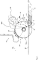
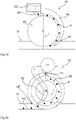
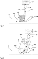
- the 1 shows a spreading unit 10, by means of which granulate portions P, namely portions of fertilizer, and isolated seed grains can be released onto an agricultural area N.
- the application unit 10 has a holder 12, via which the application unit 10 can be attached to a crossbeam of the agricultural application machine.
- the holder 12 has a parallelogram linkage 14, via which the machine components arranged on the parallelogram linkage 14 can execute a lifting movement.
- the dispensing unit 10 has a portioning device 22, a granulate delivery device 18 and a furrow opener 20, which are attached to the holder 12 via a common attachment mechanism 16.
- the fastening mechanism 16 is height-adjustable and allows the portioning device 22, the granulate dispensing device 18 and the furrow opener 20 to move in and out together.
- the furrow opener 20 is set up to push apart the soil E of the agricultural area N in order to produce a granulate deposit furrow AF having a furrow base FG.
- the granulate delivery device 18 is set up to deliver the granulate portions P produced by the portioning device 22 into the granulate deposition furrow AF that has been produced.
- the granulate delivery device 18 has a granulate delivery channel 24 which is connected to an outlet opening of the portioning device 22 .
- the granulate portion P is in the granulate discharge channel 24 in the direction of Granulate deposit furrow AF guided.
- the granulate discharge channel 24 has a channel wall, with the conveying cross section of the granulate discharge channel 24 changing in the direction of the granulate deposit furrow AF.
- the granulate discharge channel 24 has a bend, via which grains which have moved away from the granulate portion P produced are collected again or fed back to the granulate portion P.
- the portioning device 22 has a rotationally driven portioning element.
- the portioning element collects granules flowing into the portioning device 22 as it performs a rotary movement and brings them together to form a granulate portion P.
- the application unit 10 also has a grain separating device 26, by means of which seed grains are separated.
- the separated seeds are then placed on the agricultural area N by a coulter 28 .
- the separated seeds are guided via a grain delivery channel 30 in the direction of the seed furrow, which is produced by the seed coulter 28 .
- a pressure roller 34 is arranged behind the catching roller 32, via which the soil E of the agricultural area N is pressed down after the granulate portion P and the individual seeds have been deposited.
- the furrow former 20 is designed as a double-disc crowd and has two cutting discs 36a, 36b of which for the sake of clarity in the Figures 1 and 2 only one of the two is shown.
- a central axis Z extends through the centers of the cutting disks 36a, 36b of the furrow opener 20, the grain discharge channel 30 and its granulate discharge opening 44 being arranged behind the central axis Z in the direction of travel FR.
- the outlet opening of the portioning device 22 is offset in the direction of travel FR with respect to the granulate discharge opening 44 of the granulate discharge channel 24 .
- the inner curved wall of the granulate delivery channel 24 points against the direction of travel FR.
- the fastening mechanism 16 is articulated.
- the inner curved wall of the granulate delivery channel 24 now points in the direction of travel FR.
- the 3 shows that the portioning device 22 is fastened to a mounting body 38 of the furrow opener 20 via mounting members 40a, 40b.
- the mounting body 38 is a mounting plate which can be attached to a bracket 12 of a discharge unit 10 via the attachment mechanism 16 .
- the portioning device 22 is arranged behind the central axis Z of the furrow opener 20 in relation to the direction of travel FR. Furthermore, the 3 Section lines aa to ff, the associated sectional views in the Figures 5 to 10 are shown.
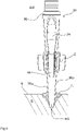
- the 4 shows a discharge path 42 along which the granulate portions P discharged from the granulate discharge opening 44 move in the direction of the furrow base FG of the granulate deposit furrow AF.
- the granulate portions P are delivered by the granulate delivery device 18 into the granulate deposit furrow AF created by the furrow opener 20 in such a way that the granulate portions P first pass through a coverage area D before reaching the furrow base FG, in which the granulate portions P are located on both sides in the coverage of the furrow opener 20. which prevents the closure of the granule deposition furrow AF in the coverage area D on both sides.
- the soil E of the agricultural area N is pushed apart by means of the furrow opener 20 by the cutting disks 36a, 36b of the furrow opener 20 in such a way that the generated granule deposition furrow AF closes in the absence of the furrow opener 20.
- the produced granulate portions P pass through a capture area F, in which the granulate deposition furrow AF already closes due to the absence of the furrow opener.
- the granule deposition furrow AF is therefore only temporarily open to accommodate the granule portions P. Even as the granulate portions P pass through the granulate deposition furrow AF, the furrow walls collapse and furrow collapse occurs.
- the granulate deposition furrow AF is therefore a self-catching furrow.
- a return flow zone Z 1 Immediately behind the cutting discs 36a, 36b of the furrow opener 20 is a return flow zone Z 1 in which the soil E previously displaced by the furrow opener 20 flows back into the granulate deposit furrow AF.
- the actual catching of the granulate portions P takes place in the reflux zone Z 1 .
- the granulate portions P are covered with soil E from above in the reflux zone Z 1 before they reach the bottom of the furrow FG.
- the furrow closure zone Z 2 adjoining the reflux zone Z 1 the granulate portions P have already reached the bottom of the furrow FG, with earth movements coming to a standstill in this area.
- the adjoining closed zone Z 3 there are no more earth movements and the granulate portions P are embedded in the soil E.
- the delivery speed at which the granulate portions P emerge from the granulate delivery opening 44 of the granulate delivery channel 24 is higher than the driving speed of the agricultural spreading machine. If the delivery speed is high in relation to the driving speed, the granulate portion P is only slightly elongated when it hits the bottom of the furrow FG, since only a short distance is covered between the impact of the first and last granule grain of the respective granulate portions P.
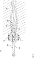
- the figure 5 shows that the cutting discs 36a, 36b of the furrow opener 20 are arranged at an angle to one another.
- the cutting discs 36a, 36b touch each other at a contact point B.
- the contact point B is in the direction of travel FR in front of the central axis Z of the furrow opener 20.
- the contact point B of the two cutting discs 36a, 36b is in the direction of travel in a front lower quarter of the cutting discs 36a, 36b . in synopsis with the side view of the 3 it follows that the touch point B is at about 7 to 8 o'clock. Behind the contact point B, the cutting discs 36a, 36b diverge.
- the 6 shows that the cutting discs 36a, 36b perform rotary movements about the axes of rotation Ra, Rb during furrow production.
- the axes of rotation Ra, Rb run through the centers of the cutting disks 36a, 36b.
- the section shown shows a granule deposition furrow AF, which has a W-shaped furrow cross-section.
- the W-shaped groove cross-section is also retained in the reflux zone Z 1 as in FIG 7 shown.
- the 7 also shows that the granulate discharge channel 24 is arranged between the two cutting discs 36a, 36b of the furrow opener 20.
- the 8 shows that the soil E of the agricultural area N is displaced by the furrow opener 20 when it is pushed apart by means of the furrow opener 20 in such a way that the tendency of the soil E to flow back resulting from the soil displacement would lead directly to a furrow closure in the absence of the furrow opener 20.
- the granulate portion P is loaded with soil E from above immediately after delivery, so that the soil E of the collapsing granulate deposit furrow AF in the capture area F absorbs the kinetic energy from the grains of the granulate portions P, in which the grains fall immediately after leaving the coverage area D are pinched and limited by the soil E in such a way that rolling in the granulate deposit furrow AF and jumping out of the granulate deposit furrow AF is not possible.
- the 10 shows that the distance between the cutting disks 36a, 36b increases from a front cutting disk area to a rear cutting disk area, so that behind the central axis Z of Granulate delivery channel 24 of the granulate delivery device 18 can be positioned.
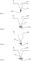
- the Figures 11 to 14 show different furrow cross-sections, which can be produced by means of a furrow opener and possibly a furrow former 54 of a discharge unit 10.
- a V-shaped or wedge-shaped groove cross-section is shown in the 11 .
- the 12 shows a furrow cross-section in which a receiving pocket extending outwards on both sides is present at the bottom of the furrow FG.
- a type of T-slot groove is created by the receiving pocket.
- the 13 shows a furrow cross-section in which the receiving furrow AF has a substantially circular receiving channel at the furrow base FG.
- the one in the 14 Granulate deposition furrow AF shown is dovetail-shaped in a lower area.
- the granulate portions P deposited in the granulate deposit furrow AF can also be decelerated in the granulate deposit furrow AF by means of a catching device 46 of the agricultural spreading machine.
- Corresponding catching devices 46 are particularly advantageous when the furrow shape cannot be designed to be sufficiently self-catching.
- the catching device 46 is a catching roller, which is arranged behind the granulate delivery device 18 in the direction of travel FR.
- the granulate portions P discharged via the granulate discharge channel 24 are caught by the catching roller 46 and pressed onto the furrow base FG of the granulate deposit furrow AF.
- the catching device 46 is designed as a skid.
- the catch skid also ensures that the granulate portions P produced are intercepted and that the intercepted granulate portions P are pressed onto the furrow base FG of the granulate depositing furrow AF.
- the bottom of the agricultural area N serves as a catch element.
- the catching device 46 is a coverr, which does not come into direct contact with the granulate portions P, but causes earth movement, over which the granulate portions P are caught.
- the 18 an embodiment is shown in which a roller is used instead of a brush.
- the catching device 46 is again a catching roller, with the depositing process being supported by a guide body 48 .
- the granulate portions P are guided in a gap between the surface of the catch roller 46 and a guide surface of the guide body 48 in the direction of the granulate deposit furrow AF.
- the 20 shows a granulate dispensing device 18, in which the granulate portions P are dispensed into a carrier brush 50, with the carrier brush 50 performing a rotational movement, so that the granulate portions P located in the carrier brush 50 can be scraped off by a scraper 52 in the vicinity of the granulate deposit furrow AF in such a way that the granule portions P leave the carrier brush 50 and are deposited on the furrow base FG of the granule deposit furrow AF.
- a chain, tab or lamella arrangement can also be used as the catching device 46 .
- a furrow former 54 can be arranged in front of the catching device 46 in the direction of travel, which adapts the furrow shape to a subsequent catching process.
- a guide unit is shown, by means of which produced granulate portions P can be transported into a granulate deposit furrow AF.
- the granulate portions P are clamped between a guide surface of a guide body 48 and a belt 58 .
- the belt 58 runs around deflection rollers 56a, 56b, via which the belt 58 is also driven. The movement of the belt conveys the granulate portions P clamped between the guide body 48 and the belt 58 in the direction of the granulate deposit furrow AF.
Landscapes
- Life Sciences & Earth Sciences (AREA)
- Soil Sciences (AREA)
- Environmental Sciences (AREA)
- Fertilizing (AREA)
- Sowing (AREA)
Applications Claiming Priority (1)
| Application Number | Priority Date | Filing Date | Title |
|---|---|---|---|
| DE102020134534.8A DE102020134534A1 (de) | 2020-12-22 | 2020-12-22 | Verfahren zum Ablegen von Granulatportionen auf eine landwirtschaftliche Nutzfläche mittels einer landwirtschaftlichen Ausbringmaschine |
Publications (1)
| Publication Number | Publication Date |
|---|---|
| EP4018799A1 true EP4018799A1 (fr) | 2022-06-29 |
Family
ID=78821938
Family Applications (1)
| Application Number | Title | Priority Date | Filing Date |
|---|---|---|---|
| EP21212409.3A Withdrawn EP4018799A1 (fr) | 2020-12-22 | 2021-12-04 | Procédé de dépôt des portions de granulé sur un terrain agricole au moyen d'une machine d'épandage agricole |
Country Status (2)
| Country | Link |
|---|---|
| EP (1) | EP4018799A1 (fr) |
| DE (1) | DE102020134534A1 (fr) |
Citations (5)
| Publication number | Priority date | Publication date | Assignee | Title |
|---|---|---|---|---|
| DE2742193A1 (de) * | 1977-09-20 | 1979-03-22 | Hilberer Maschinenbau Landmasc | Verfahren und vorrichtung zum duengen von boeden |
| DE3502510C2 (fr) * | 1985-01-25 | 1987-06-19 | Theodor Dipl.-Forstw. 8213 Aschau De Erras | |
| CA2125533A1 (fr) * | 1994-06-09 | 1995-12-10 | F. Ben Dyck | Traceur de sillon |
| EP3219186A1 (fr) * | 2016-03-17 | 2017-09-20 | Horsch Maschinen GmbH | Unité de rangs pour une machine agricole et procédé de fonctionnement d'une machine agricole |
| DE102016114692A1 (de) * | 2016-08-09 | 2018-03-01 | Amazonen-Werke H. Dreyer Gmbh & Co. Kg | Einzelkornsäeinheit |
Family Cites Families (2)
| Publication number | Priority date | Publication date | Assignee | Title |
|---|---|---|---|---|
| DE102010014447A1 (de) | 2010-04-09 | 2011-10-13 | Horsch Maschinen Gmbh | Einzelkornsäaggregat |
| DE102012105048A1 (de) | 2012-06-12 | 2013-12-12 | Horsch Maschinen Gmbh | Verteilaggregat für körniges Gut, insbesondere Säaggregat |
-
2020
- 2020-12-22 DE DE102020134534.8A patent/DE102020134534A1/de active Pending
-
2021
- 2021-12-04 EP EP21212409.3A patent/EP4018799A1/fr not_active Withdrawn
Patent Citations (5)
| Publication number | Priority date | Publication date | Assignee | Title |
|---|---|---|---|---|
| DE2742193A1 (de) * | 1977-09-20 | 1979-03-22 | Hilberer Maschinenbau Landmasc | Verfahren und vorrichtung zum duengen von boeden |
| DE3502510C2 (fr) * | 1985-01-25 | 1987-06-19 | Theodor Dipl.-Forstw. 8213 Aschau De Erras | |
| CA2125533A1 (fr) * | 1994-06-09 | 1995-12-10 | F. Ben Dyck | Traceur de sillon |
| EP3219186A1 (fr) * | 2016-03-17 | 2017-09-20 | Horsch Maschinen GmbH | Unité de rangs pour une machine agricole et procédé de fonctionnement d'une machine agricole |
| DE102016114692A1 (de) * | 2016-08-09 | 2018-03-01 | Amazonen-Werke H. Dreyer Gmbh & Co. Kg | Einzelkornsäeinheit |
Also Published As
| Publication number | Publication date |
|---|---|
| DE102020134534A1 (de) | 2022-06-23 |
Similar Documents
| Publication | Publication Date | Title |
|---|---|---|
| EP3219186B1 (fr) | Unité de rangée pour une machine agricole et procédé de fonctionnement d'une machine agricole | |
| EP1587355B1 (fr) | Dispositif de guidage de semences | |
| EP3340767B1 (fr) | Arrangement d'un soc de semis d'une machine agricole | |
| EP3281509B1 (fr) | Unité semoir monograine | |
| EP2858472B1 (fr) | Dispositif d'épandage pour matériel granulaire, en particulier dispositif à semer | |
| DE2826658C3 (de) | Sämaschine für Getreide und andere Saatgutarten | |
| EP3440908B1 (fr) | Dispositif de séparation pour matériau granulaire avec ensemble de conversion | |
| EP3417688B1 (fr) | Machine d'épandage pneumatique agricole | |
| EP1585379A1 (fr) | Systeme de dosage | |
| EP0732044B1 (fr) | Conduit pour machine agricole | |
| EP3994970B1 (fr) | Dispositif de séparation du produit à planter | |
| EP0102557B2 (fr) | Semoir | |
| DE102016204453A1 (de) | Reiheneinheit einer landwirtschaftlichen Maschine | |
| DE3405361C1 (de) | Pnaumatische Einzelkornsaemaschine | |
| DE69015465T2 (de) | Verfahren und Sämaschine zum Aussäen von Getreidesamen in den Boden. | |
| EP2636294B9 (fr) | Installation d'absorption d'énergie pour un canal d'acheminement d'un soc | |
| EP0259633B1 (fr) | Dispositif de dosage de précision, par exemple volumétriques, de matériaux en granulés dans des épandeurs de granulés | |
| EP1461989B1 (fr) | Semoir pneumatique, particulièrement semoir monograine | |
| DE102020134534A1 (de) | Verfahren zum Ablegen von Granulatportionen auf eine landwirtschaftliche Nutzfläche mittels einer landwirtschaftlichen Ausbringmaschine | |
| DE3227670C2 (fr) | ||
| DE102016204468A1 (de) | Reiheneinheit einer landwirtschaftlichen Maschine | |
| WO2025252477A1 (fr) | Semoir et rayonneur pour semoir | |
| EP1752028B1 (fr) | Semoir monograine pneumatique | |
| EP3808164A1 (fr) | Dispositif de découpage pour une matière granulée | |
| DE19614348C2 (de) | Samenkörner-Verlangsamungsvorrichtung für eine Sämaschine, und mit einer solchen Vorrichtung ausgerüstete Sämaschine |
Legal Events
| Date | Code | Title | Description |
|---|---|---|---|
| PUAI | Public reference made under article 153(3) epc to a published international application that has entered the european phase |
Free format text: ORIGINAL CODE: 0009012 |
|
| STAA | Information on the status of an ep patent application or granted ep patent |
Free format text: STATUS: THE APPLICATION HAS BEEN PUBLISHED |
|
| AK | Designated contracting states |
Kind code of ref document: A1 Designated state(s): AL AT BE BG CH CY CZ DE DK EE ES FI FR GB GR HR HU IE IS IT LI LT LU LV MC MK MT NL NO PL PT RO RS SE SI SK SM TR |
|
| STAA | Information on the status of an ep patent application or granted ep patent |
Free format text: STATUS: REQUEST FOR EXAMINATION WAS MADE |
|
| 17P | Request for examination filed |
Effective date: 20221117 |
|
| RBV | Designated contracting states (corrected) |
Designated state(s): AL AT BE BG CH CY CZ DE DK EE ES FI FR GB GR HR HU IE IS IT LI LT LU LV MC MK MT NL NO PL PT RO RS SE SI SK SM TR |
|
| P01 | Opt-out of the competence of the unified patent court (upc) registered |
Effective date: 20230523 |
|
| STAA | Information on the status of an ep patent application or granted ep patent |
Free format text: STATUS: EXAMINATION IS IN PROGRESS |
|
| 17Q | First examination report despatched |
Effective date: 20240531 |
|
| STAA | Information on the status of an ep patent application or granted ep patent |
Free format text: STATUS: THE APPLICATION IS DEEMED TO BE WITHDRAWN |
|
| 18D | Application deemed to be withdrawn |
Effective date: 20240801 |