EP4019832A1 - Beleuchtungsvorrichtung für kraftfahrzeuge - Google Patents
Beleuchtungsvorrichtung für kraftfahrzeuge Download PDFInfo
- Publication number
- EP4019832A1 EP4019832A1 EP20217181.5A EP20217181A EP4019832A1 EP 4019832 A1 EP4019832 A1 EP 4019832A1 EP 20217181 A EP20217181 A EP 20217181A EP 4019832 A1 EP4019832 A1 EP 4019832A1
- Authority
- EP
- European Patent Office
- Prior art keywords
- optical fibre
- light source
- lighting apparatus
- light
- intermediate lens
- Prior art date
- Legal status (The legal status is an assumption and is not a legal conclusion. Google has not performed a legal analysis and makes no representation as to the accuracy of the status listed.)
- Pending
Links
- 239000013307 optical fiber Substances 0.000 claims abstract description 94
- 230000000712 assembly Effects 0.000 description 8
- 238000000429 assembly Methods 0.000 description 8
- 239000000463 material Substances 0.000 description 7
- 230000003287 optical effect Effects 0.000 description 7
- 239000004033 plastic Substances 0.000 description 7
- 229920003023 plastic Polymers 0.000 description 7
- 229920003229 poly(methyl methacrylate) Polymers 0.000 description 6
- 239000004926 polymethyl methacrylate Substances 0.000 description 6
- 230000008878 coupling Effects 0.000 description 3
- 238000010168 coupling process Methods 0.000 description 3
- 238000005859 coupling reaction Methods 0.000 description 3
- 239000012141 concentrate Substances 0.000 description 2
- 230000009849 deactivation Effects 0.000 description 2
- 238000001746 injection moulding Methods 0.000 description 2
- 239000007769 metal material Substances 0.000 description 2
- 239000011248 coating agent Substances 0.000 description 1
- 238000000576 coating method Methods 0.000 description 1
- 230000001427 coherent effect Effects 0.000 description 1
- 239000006185 dispersion Substances 0.000 description 1
- 239000000835 fiber Substances 0.000 description 1
- 239000011521 glass Substances 0.000 description 1
- 238000004519 manufacturing process Methods 0.000 description 1
- 238000012986 modification Methods 0.000 description 1
- 230000004048 modification Effects 0.000 description 1
- 239000004417 polycarbonate Substances 0.000 description 1
- 229920000515 polycarbonate Polymers 0.000 description 1
- 230000011664 signaling Effects 0.000 description 1
- 230000002459 sustained effect Effects 0.000 description 1
Images



Classifications
-
- F—MECHANICAL ENGINEERING; LIGHTING; HEATING; WEAPONS; BLASTING
- F21—LIGHTING
- F21S—NON-PORTABLE LIGHTING DEVICES; SYSTEMS THEREOF; VEHICLE LIGHTING DEVICES SPECIALLY ADAPTED FOR VEHICLE EXTERIORS
- F21S45/00—Arrangements within vehicle lighting devices specially adapted for vehicle exteriors, for purposes other than emission or distribution of light
- F21S45/70—Prevention of harmful light leakage
-
- F—MECHANICAL ENGINEERING; LIGHTING; HEATING; WEAPONS; BLASTING
- F21—LIGHTING
- F21S—NON-PORTABLE LIGHTING DEVICES; SYSTEMS THEREOF; VEHICLE LIGHTING DEVICES SPECIALLY ADAPTED FOR VEHICLE EXTERIORS
- F21S43/00—Signalling devices specially adapted for vehicle exteriors, e.g. brake lamps, direction indicator lights or reversing lights
- F21S43/10—Signalling devices specially adapted for vehicle exteriors, e.g. brake lamps, direction indicator lights or reversing lights characterised by the light source
- F21S43/13—Signalling devices specially adapted for vehicle exteriors, e.g. brake lamps, direction indicator lights or reversing lights characterised by the light source characterised by the type of light source
- F21S43/14—Light emitting diodes [LED]
-
- F—MECHANICAL ENGINEERING; LIGHTING; HEATING; WEAPONS; BLASTING
- F21—LIGHTING
- F21S—NON-PORTABLE LIGHTING DEVICES; SYSTEMS THEREOF; VEHICLE LIGHTING DEVICES SPECIALLY ADAPTED FOR VEHICLE EXTERIORS
- F21S43/00—Signalling devices specially adapted for vehicle exteriors, e.g. brake lamps, direction indicator lights or reversing lights
- F21S43/20—Signalling devices specially adapted for vehicle exteriors, e.g. brake lamps, direction indicator lights or reversing lights characterised by refractors, transparent cover plates, light guides or filters
- F21S43/235—Light guides
- F21S43/236—Light guides characterised by the shape of the light guide
- F21S43/237—Light guides characterised by the shape of the light guide rod-shaped
-
- F—MECHANICAL ENGINEERING; LIGHTING; HEATING; WEAPONS; BLASTING
- F21—LIGHTING
- F21S—NON-PORTABLE LIGHTING DEVICES; SYSTEMS THEREOF; VEHICLE LIGHTING DEVICES SPECIALLY ADAPTED FOR VEHICLE EXTERIORS
- F21S43/00—Signalling devices specially adapted for vehicle exteriors, e.g. brake lamps, direction indicator lights or reversing lights
- F21S43/20—Signalling devices specially adapted for vehicle exteriors, e.g. brake lamps, direction indicator lights or reversing lights characterised by refractors, transparent cover plates, light guides or filters
- F21S43/235—Light guides
- F21S43/242—Light guides characterised by the emission area
- F21S43/245—Light guides characterised by the emission area emitting light from one or more of its major surfaces
-
- F—MECHANICAL ENGINEERING; LIGHTING; HEATING; WEAPONS; BLASTING
- F21—LIGHTING
- F21S—NON-PORTABLE LIGHTING DEVICES; SYSTEMS THEREOF; VEHICLE LIGHTING DEVICES SPECIALLY ADAPTED FOR VEHICLE EXTERIORS
- F21S43/00—Signalling devices specially adapted for vehicle exteriors, e.g. brake lamps, direction indicator lights or reversing lights
- F21S43/20—Signalling devices specially adapted for vehicle exteriors, e.g. brake lamps, direction indicator lights or reversing lights characterised by refractors, transparent cover plates, light guides or filters
- F21S43/235—Light guides
- F21S43/247—Light guides with a single light source being coupled into the light guide
-
- F—MECHANICAL ENGINEERING; LIGHTING; HEATING; WEAPONS; BLASTING
- F21—LIGHTING
- F21S—NON-PORTABLE LIGHTING DEVICES; SYSTEMS THEREOF; VEHICLE LIGHTING DEVICES SPECIALLY ADAPTED FOR VEHICLE EXTERIORS
- F21S43/00—Signalling devices specially adapted for vehicle exteriors, e.g. brake lamps, direction indicator lights or reversing lights
- F21S43/40—Signalling devices specially adapted for vehicle exteriors, e.g. brake lamps, direction indicator lights or reversing lights characterised by the combination of reflectors and refractors
Definitions
- the present invention relates to an automotive lighting apparatus.
- the present invention relates to a headlight or taillight for cars and similar vehicles, i.e. a lighting apparatus adapted to be incorporated into a motor vehicle with the function of signalling the position, the sudden deceleration and/or the turning direction, and/or with the function of lighting the area surrounding the vehicle.
- a lighting apparatus adapted to be incorporated into a motor vehicle with the function of signalling the position, the sudden deceleration and/or the turning direction, and/or with the function of lighting the area surrounding the vehicle.
- the taillights for cars and similar vehicles generally comprise: a rigid and substantially basin-shaped rear body, which is structured so as to be stably recessed into a compartment specially realized in the rear part of the bodywork of the vehicle; a front half-shell which is arranged to close the mouth of the rear body so as to surface outside the bodywork of the vehicle, and is generally provided with a plurality of transparent or semitransparent sectors, usually with a colour different from one another; and a series of lighting assemblies that are located inside the rear body, each immediately beneath a respective transparent or semitransparent sector of the front half-shell, so as to be able to selectively backlight the overlying transparent or semitransparent sector of the front half-shell.
- each transparent or semitransparent sector of the front half-shell is moreover uniquely associated with a specific light signal adapted to signal the position of the vehicle, the sudden deceleration of the vehicle or the turning direction of the vehicle during travel.
- Each lighting assembly therefore, is specifically structured to emit, on command, a light beam that, once coming out from the taillight through the corresponding transparent or semitransparent sector of the half-shell, meets the type-approval specifications (colour and light distribution) required for the corresponding light signal.
- At least one of the lighting assemblies comprises: a light-guide bar which is made of polymethylmethacrylate (PMMA) or other photoconductive material and extends inside the rear body skimming over the transparent or semitransparent sector to be backlighted, substantially for the entire length of the same sector; and one or more high-power LEDs (acronym for Light Emitting Diode) that are fixed on a small printed circuit board which, in turn, is placed inside the rear body, close to at least one of the two ends of the light-guide bar, so that the LED(s) can direct the light directly into the light-guide bar through said end.
- PMMA polymethylmethacrylate
- the light-guide bar in fact, is notoriously a hard and rigid, but relatively fragile, monolithic body thus it must be inserted into the rear body with due care.
- the or both ends of the light-guide bar must be perfectly aligned with the LEDs to avoid light leaks, and this contributes in lengthening the assembly time of the headlight.
- Optical fibres in fact, are notoriously much more flexible than a light-guide bar made of polymethylmethacrylate (PMMA) and therefore considerably simplify the assembly of the headlight/taillight.
- PMMA polymethylmethacrylate
- the optical and mechanical coupling between each optical fibre and the corresponding LED can be performed rapidly by using a fixing connector which holds the end of the optical fibre firmly in place in front of the LED.
- LEDs are point-type light sources and the optical fibres have a very small diameter
- a small converging lens is usually placed between the LED and the end of the optical fibre, which lens concentrates the light rays exiting from the LED towards the facing end of the optical fibre.
- the high-power LED(s) have been replaced by small laser emitters that guarantee a higher intensity of the emitted light.
- the light emitted by the LEDs in fact, generally has such an intensity that it can temporarily blind a person, and a broken and free-to-move optical fibre theoretically could accidentally direct the LED light outside of the headlight/taillight, towards the eye of a person stationary inside the vehicle or in the immediate nearby of the vehicle, with all the problems that this entails.
- the criticality is even greater if the high-power LED(s) are replaced by laser emitters.
- the light emitted by the laser emitter can have such an intensity that it can irreparably damage the human eye.
- Aim of the present invention is to increase the active safety of the new lighting assemblies that use optical fibres to backlight the front half-shell of the headlight/taillight.
- an automotive lighting apparatus as defined in Claim 1 and preferably, though not necessarily, in any one of the claims depending on it.
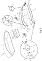
- number 1 denotes as a whole a lighting apparatus for automotive use, i.e. a lighting apparatus adapted to be mounted in a motor vehicle.
- the lighting apparatus 1 is preferably an automotive light, i.e. a lighting device particularly adapted to be placed on the front or rear part of the bodywork of a motor vehicle, with the function of emitting light signals adapted to signal the position of the vehicle and/or the sudden deceleration of the vehicle and/or the turning direction of the vehicle during travel.
- automotive light i.e. a lighting device particularly adapted to be placed on the front or rear part of the bodywork of a motor vehicle, with the function of emitting light signals adapted to signal the position of the vehicle and/or the sudden deceleration of the vehicle and/or the turning direction of the vehicle during travel.
- the lighting apparatus 1 is adapted to be fixed to the front or rear part of the bodywork of a car, van, truck, motorcycle or other similar motor vehicle, to perform the function of a headlight or taillight.
- the lighting apparatus 1 is furthermore structured so as to surface outside the vehicle.
- the lighting apparatus 1 is preferably structured to be stably recessed in the rear part of the bodywork of a car or other similar motor vehicle.
- the lighting apparatus 1 is preferably a taillight for cars and the like.
- the lighting apparatus 1 could also be structured so as to be simply fixed cantilevered on the front or rear part of the bodywork of the vehicle (not shown).
- the lighting apparatus 1 preferably comprises: a substantially rigid and preferably made of plastic material, rear body 2 which is adapted to be firmly fixed to the vehicle, preferably outside of the vehicle; and a substantially rigid and preferably made of plastic material, front half-shell 3, traditionally called lens, which is arranged to close the mouth of rear body 2, preferably so as to surface outside of the bodywork of the vehicle, and is provided with at least one transparent or semitransparent sector.
- rear body 2 is preferably substantially basin-shaped, and is preferably structured so as to be at least partially recessed into a seat specially made in the rear part of the bodywork of the vehicle (not shown).
- rear body 2 could also be structured so as to be simply fixed cantilevered on the rear part of the bodywork of the vehicle (not shown).
- the lighting device 1 moreover comprises at least one electrically-powered lighting assembly that emits light on command and is located inside the rear body 2, beneath a corresponding transparent or semitransparent sector of front half-shell 3, so as to be able to selectively backlight said transparent or semitransparent sector of front half-shell 3.
- the front half-shell 3 is preferably provided with a plurality of transparent or semitransparent sectors.
- the lighting apparatus 1 is preferably provided with a plurality of electrically-powered lighting assemblies, each of which is located inside the rear body 2 in a position such as to backlight exclusively the overlying and corresponding transparent or semitransparent sector of front half-shell 3, preferably separately and independently from the other lighting assemblies of the lighting apparatus.
- the rear body 2 is preferably made of an opaque plastic material, preferably via an injection moulding process.
- the front half-shell 3 is preferably made of a transparent or semitransparent plastic material, such as for example polycarbonate (PC) or polymethylmethacrylate (PMMA), also in this case preferably via an injection moulding process.
- a transparent or semitransparent plastic material such as for example polycarbonate (PC) or polymethylmethacrylate (PMMA), also in this case preferably via an injection moulding process.
- At least one of said lighting assemblies in turn comprises: an electrically-powered light source 5 which is placed inside the rear body 2 and is capable of emitting light on command; and an optical fibre 6 of given length and preferably with a flexible filiform structure, which extends inside the rear body 2 and has one of its two ends, hereafter called proximal end, faced and optically coupled to the light source 5 so that the light emitted by the light source 5 can freely enter into the optical fibre 6 and travel inside it.
- the optical fibre 6 is adapted to channel the light emitted by the light source 5 towards the front half-shell 3.
- the lighting assembly 4 moreover comprises a small intermediate lens 7, which is interposed between the proximal end of optical fibre 6 and the light source 5, and is adapted to channel the light exiting from the light source 5 towards the rearward proximal end of optical fibre 6.
- the intermediate lens 7 is additionally a converging lens adapted to concentrate/focus the light exiting from the light source 5 towards the behind-located proximal end of optical fibre 6.
- the optical fibre 6 has a proximal end 6a and a distal end 6b, opposite to the proximal end 6a.
- the light source 5 is arranged inside the rear body 2 facing the proximal end 6a of optical fibre 6, and is adapted to emit, on command and towards the proximal end 6a, a light beam that enters and travels inside the optical fibre 6, towards the distal end 6b.
- the intermediate lens 7 is placed between the light source 5 and the proximal end 6a of the optical fibre 6 spaced from the light source 5 and preferably abutting on the proximal end 6a of optical fibre 6.
- the optical fibre 6, in addition, is preferably arranged inside the rear body 2 so as to extend, at least for an own portion/segment of given length, locally substantially skimmed over a corresponding transparent or semitransparent sector of front half-shell 3, and is preferably structured so as to gradually diffuse outwards the light that travels inside itself, preferably at least along said portion/ segment of given length.
- the optical fibre 6 is specifically structured to channel the entering light towards its own distal end 6b, simultaneously and progressively diffusing outside of the same optical fibre 6, substantially in a radial direction, a predetermined percentage of the light as the light travels inside the same optical fibre 6.
- the optical fibre 6 is preferably a radially emitting optical fibre.
- the light source 5 is, in turn, a laser light source, i.e. a light source capable of emitting, on command, a laser beam r (namely an extremely-concentrated and collimated, coherent and monochromatic light beam) towards the intermediate lens 7 and the behind-located proximal end 6a of optical fibre 6.
- a laser light source i.e. a light source capable of emitting, on command, a laser beam r (namely an extremely-concentrated and collimated, coherent and monochromatic light beam) towards the intermediate lens 7 and the behind-located proximal end 6a of optical fibre 6.
- the intermediate lens 7 is preferably a substantially plane-convex converging lens and is preferably arranged abutting on the proximal end 6a of optical fibre 6.
- the front or light entry face of the intermediate lens 7 has a convex shape, while the rear or light exit face of intermediate lens 7 is substantially plane and preferably also rests on the proximal end 6a of optical fibre 6.
- the intermediate lens 7 preferably has a diameter greater than that of the proximal end 6a of optical fibre 6, and is preferably rigidly fixed to the proximal end 6a of optical fibre 6.
- the front face of intermediate lens 7 is preferably substantially spherical or aspherical.
- the light source 5, is preferably arranged spaced in front of the intermediate lens 7, at a distance d from the light source 5, or rather from the emitter of laser light source, preferably lower than or equal to 0,5 mm (millimetres) and more conveniently ranging between 0,1 and 0,3 mm (millimetres).
- the lighting assembly 4 moreover comprises an electronic control unit 8 that powers and/or commands the light source 5, and is preferably placed inside the rear body 2, optionally close to the bottom of the same rear body 2.
- the electronic control unit 8 is adapted to activate and deactivate the light source 5 on the basis of an external command signal.
- the external command signal commands the emission of the laser beam r.
- the lighting assembly 4 moreover comprises: at least one proximal photometric sensor 9 which is arranged beside the light source 5, or rather beside the emitter of laser light source, and/or beside the intermediate lens 7, so as to capture/ detect the light which is reflected/dispersed by the intermediate lens 7 when the light, or rather the laser beam r, enters the lens 7; and preferably also at least one distal photometric sensor 10 which is placed in front of the distal end 6b of optical fibre 6, and is adapted to capture/detect the light exiting from the distal end 6b of optical fibre 6.
- the intermediate lens 7 moreover has, on its front face or light entry face, a small surface notch or chamfer 7a, which is adapted to direct/reflect the incident light at least in part towards the proximal photometric sensor 9.
- the electronic control unit 8 is preferably adapted to command the light source 5, or rather the laser light source, also on the basis of the signals coming from said at least one proximal photometric sensor 9, and optionally also on the basis of the signals coming from said at least one distal photometric sensor 10.
- the electronic control unit 8 is preferably programmed/configured so as to autonomously switch off/deactivate the light source 5 when the intensity of the light detected by the proximal photometric sensor 9 deviates from a corresponding predetermined first reference value.
- the electronic control unit 8 is moreover programmed/configured so as to autonomously switch off/ deactivate the light source 5 when the intensity of the light detected by the proximal photometric sensor 10 deviates from a corresponding predetermined second reference value.
- the electronic control unit 8 is programmed/configured so as to activate and deactivate the light source 5 on the basis of the external command signal.
- the electronic control unit 8 is additionally programmed/configured so as to automatically deactivate the light source 5 when the intensity of the laser light detected by the proximal photometric sensor 9 deviates from said first reference value, and preferably also when the intensity of the light detected by the distal photometric sensor 10 deviates from said second reference value.
- the electronic control unit 8 is preferably programmed/configured so as to automatically deactivate the light source 5 when the intensity of the light detected by the proximal photometric sensor 9 moves outside a given first tolerance interval which is astride of said first reference value, and is preferably also substantially centred on said first reference value.
- the electronic control unit 8 is preferably also programmed/configured so as to automatically deactivate the light source 5 when the intensity of the light detected by the distal photometric sensor 10 moves outside a given second tolerance interval which is astride of said second reference value, and is preferably also substantially centred on said second reference value.
- said first reference value and/or said second reference value is/are also a function of the power/ intensity of the light beam emitted by the light source 5.
- the electronic control unit 8 is preferably programmed/configured so as to autonomously deactivate the light source 5 to interrupt /prevent the emission of the light beam, or rather of the laser beam r, when the ratio between the intensity of the light detected by the proximal photometric sensor 9 and the intensity of the light detected by the distal photometric sensor 10 deviates from a predetermined third reference value.
- the electronic control unit 8 is preferably also programmed/configured so as to automatically deactivate the light source 5 when the ratio between the intensity of the light detected by the proximal photometric sensor 9 and the intensity of the light detected by the distal photometric sensor 10 moves outside a given third tolerance interval, which is astride of said third reference value, and is preferably also substantially centred on said third reference value.
- said third reference value is a constructive parameter which is a function of the structural characteristics of the optical fibre 6, such as for example the length of the optical fibre and/or the radial emittance/ dispersion coefficient of the optical fibre 6.
- the first reference value and/or the second reference value and/or the third reference value is/are moreover stored inside the electronic control unit 8.
- the electronic control unit 8 could be programmed/configured so as to autonomously switch off/deactivate the light source 5 only on the basis of the ratio between the light intensity detected by the proximal photometric sensor 9 and the light intensity detected by the distal photometric sensor 10.
- the lighting assembly 4 adapted selectively to backlight the/each transparent or semitransparent ribbon-like sector 3a of front half-shell 3, preferably comprises: a radially-emitting optical fibre 6 that extends inside the rear body 2 so that at least a portion/segment of the optical fibre is locally substantially skimmed over the ribbon-like sector 3a to be backlighted, preferably substantially for the entire length of the ribbon-like sector 3a; and an electrically-powered light source 5 which is placed inside the rear body 2 directly facing and aligned to the intermediate lens 7, and is capable of emitting, on command and towards the intermediate lens 7, a light beam, or rather a laser beam r, which crosses the intermediate lens 7 and enters into the optical fibre 6 through the proximal end 6a of the fibre.
- the optical fibre 6 moreover has an external diameter lower than 5 mm (millimetres) and more conveniently lower than 1,2 mm (millimetres).
- the optical fibre 6 is preferably also sustained/supported by a rigid bearing structure, which is integral with rear body 2 and is preferably made of plastic material.
- the optical fibre 6 is preferably fixed on the front sidewall of a rigid and preferably made of opaque plastic material, support plate 11 that is arranged inside the rear body 2 with its front sidewall directly facing the front half-shell 3, or rather the corresponding ribbon-like sector 3a preferably substantially for the entire length of the same ribbon-like sector 3a, and with its rear sidewall facing the bottom of rear body 2.
- the support plate 11 could also protrude in cantilevered from the bottom of rear body 2.
- the lighting assembly 4 preferably also comprises centring and fixing mechanical members 12, which are adapted to rigidly connect the proximal end 6a of optical fibre 6 to the light source 5, or rather to the emitter of laser light source, and which are structured so as to stably keep the proximal end 6a of optical fibre 6 centred and stationary in front of the light source 5, or rather of the emitter of the laser light source, and/or of the intermediate lens 7.
- the intermediate lens 7 is moreover fixed to said centring and fixing mechanical members 12.
- the centring and fixing members 12 are preferably structured to directly support the intermediate lens 7 and to keep the proximal end 6a of optical fibre 6 stationary in front of the intermediate lens 7 and preferably in abutment on intermediate lens 7.
- the centring and fixing members 12 are preferably structured so as to keep the proximal end 6a of optical fibre 6 and the intermediate lens 7 stationary in front of the light source 5, or rather of the emitter of the laser light source, preferably at a distance d from the light source 5, or rather from the emitter of the laser light source, lower than 0,5 mm (millimetres) and more conveniently ranging between 0,1 and 0,3 mm (millimetres).
- the centring and fixing members 12 are preferably structured so as to contain/ accommodate the intermediate lens 7 and to stably keep the proximal end 6a of optical fibre 6 in abutments against the rear face of intermediate lens 7.
- the centring and fixing members 12 are moroever structured so as to stably keep the intermediate lens 7 at a distance d from the light source 5, or rather from the emitter of the laser light source, ranging between 0,2 and 0,25 mm (millimetres).
- the electronic control unit 8 is preferably programmed/configured so as to activate and deactivate the light source 5 on the basis of the external command signal.
- the electronic control unit 8 is preferably also programmed/configured so as to automatically switch off /deactivate the light source 5 when the intensity of the light detected by the proximal photometric sensor 9 deviates/ varies at least by 3% with respect to said first reference value, and/or when the intensity of the light detected by the distal photometric sensor 10 deviates/varies by at least 3% with respect to said second reference value.
- the first tolerance interval preferably has a width equal to 6% of said first reference value.
- the second tolerance interval preferably has a width equal to 6% of said second reference value
- the electronic control unit 8 is preferably also programmed/configured so as to automatically deactivate the light source 5 when the ratio between the intensity of the light detected by the proximal photometric sensor 9 and the intensity of the light detected by the distal photometric sensor 10 moves away/deviates by at least 10% from said third reference value.
- the third tolerance interval preferably has a width equal to 20% of said third reference value.
- proximal photometric sensor 9 and the light source 5, or rather the emitter of the laser light source are moreover placed/fixed one next to the other, on a small printed circuit board 13 which, in turn, is placed/fixed inside the rear body 2 of lighting apparatus 1, close to the proximal end 6a of optical fibre 6.
- the distance between the light source 5, or rather the emitter of the laser light source, and said at least one proximal photometric sensor 9 is preferably lower than or equal to 10 mm (millimetres), and more conveniently ranges between 1 and 8 mm (millimetres).
- the proximal photometric sensor 9 is also a photodiode.
- the distal photometric sensor 10 is preferably a photodiode.
- the lighting assembly 4 is preferably also provided with at least one temperature sensor 14 which is adapted to continuously detect the temperature of the light source 5, or rather of the emitter of the laser light source, and is preferably placed on the printed circuit board 13, in contact with or in any case close to the light source 5, or rather to the emitter of the laser light source.
- the electronic control unit 8 is preferably also connected to the temperature sensor 14, and is preferably adapted to amplify the signals coming from the proximal photometric sensor 9 and/or the signals coming from the distal photometric sensor 10 as a function of the current temperature of the light source 5, or rather of the emitter of the laser light source.
- the centring and fixing mechanical members 12 preferably comprise: a rigid and preferably made of plastic or metallic material, support socket 15 which is stably fixed on the printed circuit board 13 so as to extend as a bridge over the light source 5, or rather over the emitter of the laser light source, and over the proximal photometric sensor 9; and a ferrule connector 16 preferably made of metallic material, which is adapted to be fitted and firmly locked onto the proximal end 6a of optical fibre 6, and is also adapted to be screwed onto a corresponding threaded portion of support socket 15, so as to firmly fix the proximal end 6a of optical fibre 6 to the support socket 15.
- the threaded portion of the support socket 15 is preferably placed immediately over the light source 5, or rather immediately over the emitter of the laser light source.
- the ferrule connector 16 is preferably structured so as to be screwed onto the threaded portion of support socket 15 in order to arrange and lock the proximal end 6a of optical fibre 6 spaced over the light source 5, or rather over the emitter of the laser light source.
- the ferrule connector 16 is moreover structured to directly support the intermediate lens 7, and to interpose the intermediate lens 7 between the proximal end 6a of optical fibre 6 and the light source 5, or rather the emitter of the laser light source.
- the intermediate lens 7 could be fixed firmly on the support socket 15 spaced over the light source 5, or rather over the emitter of the laser light source, and beneath the threaded portion of - support socket 15.
- the ferrule connector 16 is preferably structured so as to be screwed onto the threaded portion of support socket 15 in order to arrange and stably lock the proximal end 6a of optical fibre 6 behind the intermediate lens 7, preferably in abutmanet on the rear face of the intermediate lens 7.
- the electronic control unit 8 activates and deactivates the light source 5 on the basis of the external command signal.
- the intermediate lens 7 is capable of minimizing and bringing almost to zero the amount of light that is reflected back towards the light source 5 and towards the proximal photometric sensor 9.
- the presence of the surface notch or chamfer 7a allows to deviate /reflect in any case a very small part of the incident light towards the proximal photometric sensor 9, allowing to the latter to detect something.
- the intensity of the light reflected back towards the proximal photometric sensor 9 has a value proportional to the power of the light beam, or rather of the laser beam r, emitted by the light source 5.
- the intensity of the light reflected back towards the proximal photometric sensor 9 remains substantially constant as long as the intermediate lens 7 and the rearward proximal end 6a of optical fibre 6 are perfectly aligned and coupled to the light source 5.
- any variation in the position of the intermediate lens 7 and/or of the proximal end 6a of optical fibre 6 with respect to the ideal position causes a variation in the intensity of the light directed towards the proximal photometric sensor 9.
- any variation in the light energy detected by the proximal photometric sensor 9 is indicative of the breakage of optical fibre 6, of the incorrect positioning of intermediate lens 7 and/or of the optical fibre 6 with respect to the light source 5, perhaps due to the occurred breakage of the lighting apparatus 1, or to the incorrect assembly/optical coupling of intermediate lens 7 and of optical fibre 6 with respect to the light source 5.
- the distal photometric sensor 10 detects the intensity of the light exiting from the distal end 6b of optical fibre 6. If the optical fibre 5, the intermediate lens 7 and the optical fibre 6 are correctly dimensioned, the amount of light that reaches the distal end 6b of the optical fibre 6 and is dispersed outside the optical fibre is minimal, but is still present.
- the intensity of the light coming out from the distal end 6b of the optical fibre is in any case proportional to the power of the light beam, or rather of the laser beam r, emitted by the light source 5.
- any variation of the light energy detected by the distal photometric sensor 10 is indicative of the breakage of the optical fibre 6, or of the incorrect positioning of optical fibre 6 on the relative supporting structure, or rather on the sidewall of support plate 11, probably due to the occurred breakage of the lighting apparatus 1.
- the electronic control unit 8 is programmed/configured so as to activate and deactivate the light source 5 on the basis of the external command signal.
- the electronic control unit 8 is programmed /configured so as to autonomously switch off/deactivate the light source 5 when the intensity of the light detected by the proximal photometric sensor 9 deviates from said first predetermined reference value; and/or when the intensity of the light detected by the distal photometric sensor 10 deviates from said second predetermined reference value; and/or when the ratio between the intensity of the light detected by the proximal photometric sensor 9 and the intensity of the light detected by the distal photometric sensor 10 deviates from said third predetermined reference value.
- the lighting assembly 4 thus configured prevents the light beam emitted by the light source 5 from being accidentally directed outside of the lighting apparatus 1 in the event of a broken or badly arranged optical fibre 6.
- the presence of the intermediate lens 7 allows to channel almost all of the light emitted by the light source 5 towards the proximal end 6a of the optical fibre 6.
- the presence of the surface notch or chamfer 7a on the front face of lens 7 allows to divert a very small amount of light towards the proximal photometric sensor 9, thus allowing the electronic control unit 8 to deactivate the light source 5 promptly in the event of breakage of the lighting apparatus 1.
- the intermediate lens 7 minimizes the leaks of light on entering into the optical fibre 6, while the surface notch or chamfer 7a suitably directs the few light leaks towards the proximal photometric sensor 9 allowing the operation of the electronic control unit 8.
- the use of the ratio between the intensity of the light detected by the proximal photometric sensor 9 and the intensity of the light detected by the distal photometric sensor 10, as a reference parameter for the automatic deactivation of the light source 5, makes the lighting assembly 4 very reliable and safe.
- the automatic deactivation of the light source 5 becomes independent of the intensity of the light beam, or rather of the laser beam r, momentarily emitted by the light source 5, allowing to eliminate the operating problems resulting from the considerable performance differences found in laser light sources currently on the market.
- the power of the laser beam r emitted by the laser light sources currently on the market can vary significantly and suddenly depending on the production batch of the laser light source, on the age of the laser light source, on the temperature reached by the emitter of the laser light source, and/or on the intensity of the electric current circulating at that moment in the emitter of the laser light source.
- the optical fibre 6 could be structured so as to channel light from the proximal end 6a to the distal end 6b for total internal reflection, substantially without leaks along its entire length.
- the optical fibre 6 could be a conventional optical fibre.
- the light source 5 of lighting assembly 4 could be a LED (acronym for Light Emitting Diode) possibly surmounted by an optical collimator capable of collimating the light rays emitted by the LED towards the intermediate lens 7.
- the lighting assembly 4 could be provided with two proximal photometric sensors 9 arranged on opposite sides of the light source 5, or rather of the emitter of the laser light source.
- the front face of intermediate lens 7, in turn, could be provided with two different surface notches or chamfers 7a, which are adapted to direct/reflect the incident light each towards a respective proximal photometric sensor 9.
- the lighting apparatus 1 can be also located inside the motor vehicle, for example to illuminate all or part of the passenger compartment of the vehicle.
- the lighting apparatus 1 can be advantageously placed/ incorporated within the door 100 of the vehicle, in order to illuminate the surrounding space.
- the rear body 2 is adapted to be firmly fixed to the vehicle, inside the same vehicle.
- the lighting apparatus 1 is preferably oblong in shape, and is preferably recessed into the inner coating panel 101 of the door 100 so as to form a light strip that illuminates the armrest area.
- the rear body 2 is preferably oblong in shape and is firmly fixed or incorporated into the panel 101 of door 100.
- the front half-shell 3, on the other hand, preferably has a ribbon-like structure and is arranged to close the mouth of the rear body 2, preferably substantially along the entire length of the rear body 2.
- the optical fibre 6 extends inside the rear body 2, preferably substantially along the entire length of the latter.
- the optical fibre 6 is moreover fixed to the crest of a longitudinal rib 110 protruding inside the rear body 2, preferably substantially along the entire length of the latter or of the optical fibre 6.
- the inner surface of rear body 2 preferably also has a metallic mirror finishing so as to reflect the incident light towards the front half-shell 3.
- the lighting apparatus 1 is preferably provided with a single lighting assembly 4 which is adapted to backlight the entire front half-shell 3.
- the light source 5 can also be arranged outside of the rear body 2, preferably on the back of panel 101, i.e. inside the door 100.
- the lighting apparatus 1 can be incorporated also in the dashboard of the vehicle, for example for illuminating or backlighting the perimeter of the instrument panel, or inside the central console, for example for illuminating or backlighting a control panel placed therein.
Landscapes
- Engineering & Computer Science (AREA)
- General Engineering & Computer Science (AREA)
- Physics & Mathematics (AREA)
- Microelectronics & Electronic Packaging (AREA)
- Optics & Photonics (AREA)
- Lighting Device Outwards From Vehicle And Optical Signal (AREA)
Priority Applications (1)
| Application Number | Priority Date | Filing Date | Title |
|---|---|---|---|
| EP20217181.5A EP4019832A1 (de) | 2020-12-24 | 2020-12-24 | Beleuchtungsvorrichtung für kraftfahrzeuge |
Applications Claiming Priority (1)
| Application Number | Priority Date | Filing Date | Title |
|---|---|---|---|
| EP20217181.5A EP4019832A1 (de) | 2020-12-24 | 2020-12-24 | Beleuchtungsvorrichtung für kraftfahrzeuge |
Publications (1)
| Publication Number | Publication Date |
|---|---|
| EP4019832A1 true EP4019832A1 (de) | 2022-06-29 |
Family
ID=74858174
Family Applications (1)
| Application Number | Title | Priority Date | Filing Date |
|---|---|---|---|
| EP20217181.5A Pending EP4019832A1 (de) | 2020-12-24 | 2020-12-24 | Beleuchtungsvorrichtung für kraftfahrzeuge |
Country Status (1)
| Country | Link |
|---|---|
| EP (1) | EP4019832A1 (de) |
Cited By (1)
| Publication number | Priority date | Publication date | Assignee | Title |
|---|---|---|---|---|
| WO2024009010A1 (fr) * | 2022-07-06 | 2024-01-11 | Stellantis Auto Sas | Assemblage pour bloc optique d'éclairage et/ou de signalisation à laser de véhicule automobile |
Citations (5)
| Publication number | Priority date | Publication date | Assignee | Title |
|---|---|---|---|---|
| DE102012215702A1 (de) * | 2012-09-05 | 2014-03-06 | Osram Gmbh | Beleuchtungseinrichtung |
| KR20160012467A (ko) * | 2014-07-24 | 2016-02-03 | 에스엘 주식회사 | 차량용 램프의 제어장치 |
| EP3037716A1 (de) * | 2014-12-22 | 2016-06-29 | Stanley Electric Co., Ltd. | Fahrzeug-beleuchtungsvorrichtung mit einer laser-lichtquelle und leuchtstoffmaterial |
| WO2017186529A1 (en) * | 2016-04-27 | 2017-11-02 | Lumileds Holding B.V. | Laser-based light source |
| EP3241709A1 (de) * | 2016-05-04 | 2017-11-08 | Valeo Vision | Leuchtmodul, das ein laserelement umfasst |
-
2020
- 2020-12-24 EP EP20217181.5A patent/EP4019832A1/de active Pending
Patent Citations (5)
| Publication number | Priority date | Publication date | Assignee | Title |
|---|---|---|---|---|
| DE102012215702A1 (de) * | 2012-09-05 | 2014-03-06 | Osram Gmbh | Beleuchtungseinrichtung |
| KR20160012467A (ko) * | 2014-07-24 | 2016-02-03 | 에스엘 주식회사 | 차량용 램프의 제어장치 |
| EP3037716A1 (de) * | 2014-12-22 | 2016-06-29 | Stanley Electric Co., Ltd. | Fahrzeug-beleuchtungsvorrichtung mit einer laser-lichtquelle und leuchtstoffmaterial |
| WO2017186529A1 (en) * | 2016-04-27 | 2017-11-02 | Lumileds Holding B.V. | Laser-based light source |
| EP3241709A1 (de) * | 2016-05-04 | 2017-11-08 | Valeo Vision | Leuchtmodul, das ein laserelement umfasst |
Cited By (2)
| Publication number | Priority date | Publication date | Assignee | Title |
|---|---|---|---|---|
| WO2024009010A1 (fr) * | 2022-07-06 | 2024-01-11 | Stellantis Auto Sas | Assemblage pour bloc optique d'éclairage et/ou de signalisation à laser de véhicule automobile |
| FR3137741A1 (fr) * | 2022-07-06 | 2024-01-12 | Psa Automobiles Sa | Assemblage pour bloc optique d’éclairage et/ou de signalisation à laser de véhicule automobile |
Similar Documents
| Publication | Publication Date | Title |
|---|---|---|
| US11465551B2 (en) | Automotive lighting apparatus and relative control method | |
| EP2548769B1 (de) | Rücklicht für ein Automobil | |
| EP2157363A2 (de) | Optisches Element für eine Fahrzeugleuchte | |
| US11754250B2 (en) | Vehicle lamp | |
| CA2717729A1 (en) | Door mirror device | |
| EP3248840B1 (de) | Fahrzeugsbeleuchtungseinrichtung | |
| KR101979570B1 (ko) | 차량용 램프 | |
| JP7456281B2 (ja) | 車両用導光体及び車両用灯具 | |
| EP3982040A1 (de) | Beleuchtungsvorrichtung für kraftfahrzeuge und zugehöriges steuerungsverfahren | |
| US12181124B2 (en) | Tail light for a motor vehicle | |
| KR101820500B1 (ko) | 백라이트 유닛 | |
| EP3839329B1 (de) | Automotive beleuchtungsvorrichtung | |
| KR101987295B1 (ko) | 차량용 램프 | |
| JP2022069185A (ja) | 車両用灯具 | |
| ES2972842T3 (es) | Faro de automóvil | |
| EP4296564B1 (de) | Kraftfahrzeuglicht | |
| JP6632261B2 (ja) | サイドターンシグナルランプ | |
| EP4023935B1 (de) | Kraftfahrzeuglicht | |
| EP4160082B1 (de) | Fahrzeugleuchte | |
| KR20200067578A (ko) | 차량용 램프 | |
| JP2023111587A (ja) | 車両用灯具 | |
| KR200267312Y1 (ko) | 자동차용 등화 장치 | |
| KR20220086035A (ko) | 차량용 램프 장치 | |
| KR200213506Y1 (ko) | 안전등화장치 | |
| JP2021174570A (ja) | 車両用灯具 |
Legal Events
| Date | Code | Title | Description |
|---|---|---|---|
| PUAI | Public reference made under article 153(3) epc to a published international application that has entered the european phase |
Free format text: ORIGINAL CODE: 0009012 |
|
| STAA | Information on the status of an ep patent application or granted ep patent |
Free format text: STATUS: THE APPLICATION HAS BEEN PUBLISHED |
|
| AK | Designated contracting states |
Kind code of ref document: A1 Designated state(s): AL AT BE BG CH CY CZ DE DK EE ES FI FR GB GR HR HU IE IS IT LI LT LU LV MC MK MT NL NO PL PT RO RS SE SI SK SM TR |
|
| STAA | Information on the status of an ep patent application or granted ep patent |
Free format text: STATUS: REQUEST FOR EXAMINATION WAS MADE |
|
| 17P | Request for examination filed |
Effective date: 20221227 |
|
| RBV | Designated contracting states (corrected) |
Designated state(s): AL AT BE BG CH CY CZ DE DK EE ES FI FR GB GR HR HU IE IS IT LI LT LU LV MC MK MT NL NO PL PT RO RS SE SI SK SM TR |
|
| STAA | Information on the status of an ep patent application or granted ep patent |
Free format text: STATUS: EXAMINATION IS IN PROGRESS |
|
| 17Q | First examination report despatched |
Effective date: 20240625 |