EP4019954A1 - Messzelle mit verdrehsicherung - Google Patents
Messzelle mit verdrehsicherung Download PDFInfo
- Publication number
- EP4019954A1 EP4019954A1 EP20216674.0A EP20216674A EP4019954A1 EP 4019954 A1 EP4019954 A1 EP 4019954A1 EP 20216674 A EP20216674 A EP 20216674A EP 4019954 A1 EP4019954 A1 EP 4019954A1
- Authority
- EP
- European Patent Office
- Prior art keywords
- measuring cell
- rotation device
- opening
- connection
- teeth
- Prior art date
- Legal status (The legal status is an assumption and is not a legal conclusion. Google has not performed a legal analysis and makes no representation as to the accuracy of the status listed.)
- Pending
Links
Images


Classifications
-
- G—PHYSICS
- G01—MEASURING; TESTING
- G01N—INVESTIGATING OR ANALYSING MATERIALS BY DETERMINING THEIR CHEMICAL OR PHYSICAL PROPERTIES
- G01N27/00—Investigating or analysing materials by the use of electric, electrochemical, or magnetic means
- G01N27/26—Investigating or analysing materials by the use of electric, electrochemical, or magnetic means by investigating electrochemical variables; by using electrolysis or electrophoresis
- G01N27/28—Electrolytic cell components
- G01N27/30—Electrodes, e.g. test electrodes; Half-cells
- G01N27/302—Electrodes, e.g. test electrodes; Half-cells pH sensitive, e.g. quinhydron, antimony or hydrogen electrodes
-
- F—MECHANICAL ENGINEERING; LIGHTING; HEATING; WEAPONS; BLASTING
- F16—ENGINEERING ELEMENTS AND UNITS; GENERAL MEASURES FOR PRODUCING AND MAINTAINING EFFECTIVE FUNCTIONING OF MACHINES OR INSTALLATIONS; THERMAL INSULATION IN GENERAL
- F16L—PIPES; JOINTS OR FITTINGS FOR PIPES; SUPPORTS FOR PIPES, CABLES OR PROTECTIVE TUBING; MEANS FOR THERMAL INSULATION IN GENERAL
- F16L33/00—Arrangements for connecting hoses to rigid members; Rigid hose-connectors, i.e. single members engaging both hoses
- F16L33/30—Arrangements for connecting hoses to rigid members; Rigid hose-connectors, i.e. single members engaging both hoses comprising parts inside the hoses only
-
- G—PHYSICS
- G01—MEASURING; TESTING
- G01N—INVESTIGATING OR ANALYSING MATERIALS BY DETERMINING THEIR CHEMICAL OR PHYSICAL PROPERTIES
- G01N27/00—Investigating or analysing materials by the use of electric, electrochemical, or magnetic means
- G01N27/26—Investigating or analysing materials by the use of electric, electrochemical, or magnetic means by investigating electrochemical variables; by using electrolysis or electrophoresis
- G01N27/28—Electrolytic cell components
- G01N27/283—Means for supporting or introducing electrochemical probes
-
- G—PHYSICS
- G01—MEASURING; TESTING
- G01N—INVESTIGATING OR ANALYSING MATERIALS BY DETERMINING THEIR CHEMICAL OR PHYSICAL PROPERTIES
- G01N27/00—Investigating or analysing materials by the use of electric, electrochemical, or magnetic means
- G01N27/26—Investigating or analysing materials by the use of electric, electrochemical, or magnetic means by investigating electrochemical variables; by using electrolysis or electrophoresis
- G01N27/416—Systems
- G01N27/4163—Systems checking the operation of, or calibrating, the measuring apparatus
- G01N27/4165—Systems checking the operation of, or calibrating, the measuring apparatus for pH meters
-
- G—PHYSICS
- G01—MEASURING; TESTING
- G01N—INVESTIGATING OR ANALYSING MATERIALS BY DETERMINING THEIR CHEMICAL OR PHYSICAL PROPERTIES
- G01N21/00—Investigating or analysing materials by the use of optical means, i.e. using sub-millimetre waves, infrared, visible or ultraviolet light
- G01N21/01—Arrangements or apparatus for facilitating the optical investigation
- G01N21/03—Cuvette constructions
- G01N21/05—Flow-through cuvettes
Definitions
- the present invention relates to a measuring cell, a connection adapter and a system according to the independent patent claims.
- connection hoses on the measuring cells is problematic due to the high torques.
- the object of the present invention is to eliminate the disadvantages of the prior art and in particular to improve the assembly of the measuring cells on the connecting hoses.
- a measuring cell is provided with at least one opening for a fluid, the measuring cell having at least one anti-rotation device, the at least one anti-rotation device being arranged on the at least one opening, the at least one anti-rotation device being designed to have a form-fitting effect.
- the form-fitting effect of the at least one anti-rotation device advantageously makes it possible to produce the anti-rotation device in a simple manner.
- no material connection is required, so that welding does not have to be carried out, for example.
- the form-fitting connection enables easy connection and release of the anti-twist device and thus easy assembly and disassembly of the connection between the measuring cell and a connection hose or a connection adapter of a connection hose.
- the measuring cell can be a flow-through measuring cell which has an inlet opening for the inflow of a fluid and an outlet opening for the outflow of the fluid.
- the measuring cell can be a tank that has only a single opening for the fluid to run in or flow out.
- the measuring cell is a pH measuring cell, in particular a pH measuring cell through which flow can take place.
- the measuring cell can be used to carry out conductivity measurements, electrochemical measurements, temperature measurements and measurements of the interactions with electromagnetic radiation, in particular an optical absorption measurement.
- the absorption of the torque is particularly efficient if the teeth are preferably arranged, in particular equidistantly, around the at least one opening, in particular in a ring shape.
- connection adapter it is advantageously possible to establish a connection between the anti-rotation device on the measuring cell and the anti-rotation device on the connection adapter, with which a torque can be absorbed particularly efficiently.
- a form-fitting connection can advantageously be produced, so that a particularly easily detachable and re-establishable connection can be achieved.
- the form-fitting effect of the anti-rotation device it is advantageously possible to produce the anti-rotation device in a simple manner. In particular, no material connection is required, so that welding does not have to be carried out, for example.
- the form-fitting connection allows for easy Connecting and loosening the anti-rotation device and thus easy assembly and disassembly of the connection between the measuring cell and the connection adapter.
- the anti-rotation device is designed such that it can be latched to the at least one anti-rotation device of the measuring cell, as a result of which particularly simple assembly and disassembly can be made possible.
- the anti-rotation device is designed in particular in such a way that it can absorb the highest possible torque with the smallest possible installation space and material consumption. In particular, it is advantageous if the anti-rotation device experiences a low radially directed reaction force when a torque is applied to contact surfaces.
- loaded contact surfaces of the anti-rotation device can be secured against radial slipping in the radial direction by positive locking (e.g. by a convex convex and/or concave shape).
- the anti-rotation device can be equipped at least with substantially radially oriented contact surfaces, in particular for the sake of manufacturing simplification.
- the anti-rotation device of the measuring cell and the connection adapter have approximately the same load-bearing capacity.
- the anti-rotation device is also advantageous to attach the anti-rotation device to only one side surface (e.g. on a cylindrical lateral surface and/or on an annular end face) to connect to the anti-rotation device of the other part.
- the teeth of the anti-twist device of the connection adapter make contact with the teeth of the anti-twist device of the measuring cell on contact surfaces.
- the contact surfaces are each defined by a height H and a width B of the teeth.
- a particularly high load-bearing capacity is advantageously achieved if the ratio of the width B to the height H of a tooth or several teeth of the measuring cell and/or the connection adapter is in the range 0.5 ⁇ B/H ⁇ 2, preferably 1/1.2 ⁇ B /H ⁇ 1/0.8, particularly preferably B/H is approximately equal to 1.
- the contact surfaces of the teeth of the anti-twist device of the connection adapter and/or the teeth of the anti-twist device of the measuring cell are preferably rectangular, in particular square.
- a system comprising a measuring cell according to the invention and at least one connection adapter according to the invention is also provided.
- a measuring cell according to the invention and at least one connection adapter according to the invention are also provided.
- the measuring cell is particularly advantageous to form the measuring cell at least partially, preferably predominantly, from plastic and/or rubber. Thus, a cost-effective production of the measuring cell is possible.
- the measuring cell can be designed as a disposable measuring cell.
- the measuring cell can be produced as a disposable measuring cell, in particular made from predominantly, preferably at least 90%, more preferably at least 95%, chemical elements with an atomic number of less than 17.
- the measuring cell is gamma-permeable to such an extent that a complete and homogeneous exposure of the measuring room to gamma rays for disinfection is possible.
- the production for shipping or transport of the measuring cells according to the invention is greatly simplified, since the measuring cells can be exposed to gamma rays in the packaged state and disinfected accordingly.
- contamination during the packaging of the measuring cells can be ruled out and the packaging can be carried out accordingly at low cost.
- an exemplary measuring cell 1 according to the invention is shown, the measuring cell 1 in this exemplary embodiment being designed as a pH measuring cell 1 through which a fluid can flow.
- the measuring cell 1 in this exemplary embodiment being designed as a pH measuring cell 1 through which a fluid can flow.
- other measuring cells are also conceivable, in particular measuring cells that are designed as a tank with only one opening or measuring cells that measure variables other than the pH value.
- the measuring cell 1 has a measuring space 4 delimited by a measuring cell body 5 .
- the fluid flows through the measuring chamber 4 , the pH value of which is measured with a combination electrode (not shown) that can be plugged into the measuring chamber 4 .
- the measuring cell has an inlet opening 2 for the inlet of the fluid and an outlet opening 3 for the outlet of the fluid.
- An anti-rotation device 17 ′ is arranged at the inlet opening 2 and a further anti-rotation device 17 is arranged at the outlet opening 3 .
- the anti-rotation devices 17, 17' are designed as toothings with a plurality of teeth 17, 17' which are arranged in a ring and equidistantly.
- connection adapter 30 shows an embodiment of a connection adapter 30 according to the invention, through which the fluid is supplied or removed.
- the connection adapter 30 is connected with its receiving section 32 to the inlet opening 2 or the outlet opening 3 of the measuring cell 1 .
- This connection is in particular a plug-in connection, in particular a detachable or non-detachable latching connection.
- connection piece 33 At the other end of the connection adapter 30 there is a connection piece 33 to which a line for the fluid can be connected.
- the connection adapter 30 has an anti-rotation device 31, 31'.
- the anti-rotation device 31,31' is designed as a toothing with a plurality of teeth 31,31' which are arranged in a ring shape and equidistantly.
- the anti-rotation device 31, 31' engages in the anti-rotation device 17, 17' of the connected inlet opening 2 or outlet opening 3 and prevents unintentional twisting during operation of the measuring cell 1.
- the teeth 17, 17' of the measuring cell 1 have contact surfaces K1.
- the teeth 31,31' of the connection adapter 30,30' have contact surfaces K2.
- the contact surfaces K1 contact the contact surfaces K2 and form the desired anti-twist device.
- the contact areas K1, K2 are selected to be square.
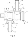
- FIG 3 shows a schematic view of the measuring cell 1 according to the invention with two connection adapters 30, 30' according to the invention, which are connected to the inlet opening 2 and the outlet opening 3, respectively.
- Each connection adapter 30, 30' has an anti-twist device 31,31' in the respective receiving section 32,32'.
- the respective anti-rotation device 31, 31' engages in the respective anti-rotation device 17, 17' of the connected inlet opening 2 or outlet opening 3 and prevents unintentional rotation of the connection adapters 30, 30' during operation of the measuring cell 1.
Landscapes
- Health & Medical Sciences (AREA)
- Chemical & Material Sciences (AREA)
- Life Sciences & Earth Sciences (AREA)
- Analytical Chemistry (AREA)
- General Health & Medical Sciences (AREA)
- Molecular Biology (AREA)
- Pathology (AREA)
- Chemical Kinetics & Catalysis (AREA)
- Electrochemistry (AREA)
- Physics & Mathematics (AREA)
- Immunology (AREA)
- Biochemistry (AREA)
- General Physics & Mathematics (AREA)
- Engineering & Computer Science (AREA)
- General Engineering & Computer Science (AREA)
- Mechanical Engineering (AREA)
- Optical Measuring Cells (AREA)
- Motorcycle And Bicycle Frame (AREA)
- Measuring Pulse, Heart Rate, Blood Pressure Or Blood Flow (AREA)
- Measuring Oxygen Concentration In Cells (AREA)
Abstract
Description
- Die vorliegende Erfindung betrifft eine Messzelle, einen Anschlussadapter sowie und ein System gemäß den nebengeordneten Patentansprüchen.
- Bei herkömmlichen Messzellen hat sich im Betrieb gezeigt, dass die Montage von Anschlussschläuchen an die Messzellen aufgrund von hohen Drehmomenten problematisch ist.
- Aufgabe der vorliegenden Erfindung ist es, die Nachteile des Stands der Technik zu beseitigen und insbesondere die Montage der Messzellen an die Anschlussschläuche zu verbessern.
- Diese Aufgabe wird mit den Merkmalen der nebengeordneten Patentansprüche gelöst. Vorteilhafte Weiterbildungen der Erfindung sind in den Unteransprüchen angegeben. In den Rahmen der Erfindung fallen auch sämtliche Kombinationen aus zumindest zwei in der Beschreibung, den Ansprüchen und/oder den Figuren offenbarten Merkmalen. Bei angegebenen Wertebereichen sollen auch innerhalb der genannten Grenzen liegende Werte als Grenzwerte offenbart gelten und in beliebiger Kombination beanspruchbar sein. Zur Vermeidung von Wiederholungen sollen systemgemäß offenbarte Merkmale auch als vorrichtungsgemäß offenbart gelten und beansprucht sein. Ebenso sollen vorrichtungsgemäß offenbarte Merkmale auch als systemgemäß offenbart gelten und beansprucht sein.
- Erfindungsgemäß vorgesehen ist eine Messzelle mit mindestens einer Öffnung für ein Fluid, wobei die Messzelle mindestens eine Verdrehsicherungseinrichtung aufweist, wobei die mindestens eine Verdrehsicherungseinrichtung an der mindestens einen Öffnung angeordnet ist, wobei die mindestens eine Verdrehsicherungseinrichtung formschlüssig wirkend ausgebildet ist.
- Vorteilhaft ist es durch die formschlüssige Wirkung der mindestens einen Verdrehsicherungseinrichtung möglich, die Verdrehsicherung auf einfache Weise herzustellen. Insbesondere ist keine stoffschlüssige Verbindung erforderlich, so dass beispielsweise kein Verschweißen durchgeführt werden muss. Außerdem ermöglicht die formschlüssige Verbindung ein leichtes Verbinden und Lösen der Verdrehsicherung und somit eine leichte Montage und Demontage der Verbindung zwischen der Messzelle und einem Anschlussschlauch bzw. einem Anschlussadapter eines Anschlussschlauchs.
- Die Messzelle kann eine durchströmbare Messzelle sein, die eine Eintrittsöffnung zum Einlauf eines Fluids und eine Austrittsöffnung zum Auslauf des Fluids aufweist. Alternativ kann es sich bei der Messzelle um einen Tank handeln, der nur eine einzige Öffnung zum Einlaufen bzw. Auflaufen des Fluids aufweist.
- Insbesondere handelt es sich bei der Messzelle um eine pH-Messzelle, insbesondere um eine durchströmbare pH-Messzelle. Es können in der Messzelle aber auch andere Messungen von Eigenschaften eines Fluids erfolgen. Es können insbesondere mit der Messzelle Leitfähigkeitsmessungen, elektrochemische Messungen, Temperaturmessungen und Messungen der Wechselwirkungen mit elektromagnetischer Strahlung, insbesondere eine optische Absorptionsmessung, durchgeführt werden.
- Bevorzugt ist vorgesehen, dass die mindestens eine Verdrehsicherungseinrichtung mehrere Zähne aufweist. Dadurch ist es vorteilhaft möglich, dass ein Drehmoment, das an der mindestens einen Öffnung entsteht, besonders effizient aufgenommen wird, so dass ein unerwünschtes Verdrehen verhindert werden kann.
- Besonders effizient ist die Aufnahme des Drehmoments, wenn bevorzugt die Zähne, insbesondere äquidistant, um die mindestens eine Öffnung herum, insbesondere ringförmig, angeordnet sind.
- Die Erfindung betrifft weiterhin einen Anschlussadapter zur Verbindung mit mindestens einer Öffnung einer erfindungsgemäßen Messzelle, aufweisend:
- ein Anschlussstück zum Anschluss einer Leitung für ein Fluid,
- einen Aufnahmeabschnitt zur Aufnahme der mindestens einen Öffnung der Messzelle, und
- eine Verdrehsicherungseinrichtung, wobei die Verdrehsicherungseinrichtung zum formschlüssigen Eingriff in die mindestens eine Verdrehsicherungseinrichtung an der mindestens einen Öffnung der Messzelle ausgebildet ist.
- Dadurch ist es vorteilhaft möglich, eine Verbindung zwischen der Verdrehsicherungseinrichtung an der Messzelle und der Verdrehsicherungseinrichtung am Anschlussadapter herzustellen, mit der ein Drehmoment besonders effizient aufgenommen werden kann. Insbesondere ist vorteilhaft eine formschlüssige Verbindung herstellbar, so dass eine besonders leicht lösbare und wiederherstellbare Verbindung erreichbar ist.
- Vorteilhaft ist es durch die formschlüssige Wirkung der Verdrehsicherungseinrichtung möglich, die Verdrehsicherung auf einfache Weise herzustellen. Insbesondere ist keine stoffschlüssige Verbindung erforderlich, so dass beispielsweise kein Verschweißen durchgeführt werden muss. Außerdem ermöglicht die formschlüssige Verbindung ein leichtes Verbinden und Lösen der Verdrehsicherung und somit eine leichte Montage und Demontage der Verbindung zwischen der Messzelle und dem Anschlussadapter.
- Bevorzugt ist vorgesehen, dass die Verdrehsicherungseinrichtung mehrere Zähne aufweist, wobei die Zähne bevorzugt, insbesondere äquidistant, um den Aufnahmeabschnitt herum, insbesondere ringförmig, angeordnet sind. Dadurch ist vorteilhaft eine besonders effiziente Aufnahme eines Drehmoments möglich. Insbesondere ist die Verdrehsicherungseinrichtung mit der mindestens einen Verdrehsicherungseinrichtung der Messzelle verrastbar ausgebildet, wodurch eine besonders einfache Montage und Demontage ermöglicht werden kann.
- Die Verdrehsicherungseinrichtung ist insbesondere derart ausgelegt, dass sie möglichst hohe Drehmoment bei möglichst geringem Bauraum und Materialverbrauch aufnehmen kann. Insbesondere ist es vorteilhaft, wenn die Verdrehsicherungseinrichtung bei Aufbringen eines Drehmomentes an Kontaktflächen eine geringe radial gerichtete Reaktionskraft erfahren.
- Insbesondere können belastete Berührungsflächen der Verdrehsicherungseinrichtung in radialer Richtung durch Formschluss gegen radiales Abgleiten gesichert sein (z.b. durch eine konvexe Konvexe und/oder konkave Ausformung). Weiterhin kann die Verdrehsicherungseinrichtung insbesondere zur fertigungstechnischen Vereinfachung zumindest mit im wesentlichen Radial orientierten Berührungsflächen ausgestattet sein.
- Weiterhin ist es insbesondere vorteilhaft, wenn die Verdrehsicherungseinrichtung der Messzelle und des Anschlussadapters eine in etwa gleiche Tragfähigkeit aufweisen.
- Insbesondere ist es weiterhin vorteilhaft, die Verdrehsicherungseinrichtung nur an einer Seitenfläche (z.B. an einer zylindrischen Mantelfläche und/oder an einer ringförmigen Stirnfläche) an die Verdrehsicherungseinrichtung des anderen Teils anzubinden.
- Die Zähne der Verdrehsicherung des Anschlussadapters kontaktieren die Zähne der Verdrehsicherung der Messzelle an Kontaktflächen. Die Kontaktflächen werden jeweils definiert durch eine Höhe H und eine Breite B der Zähne.
- Insbesondere ergibt sich vorteilhaft eine besonders hohe Tragfähigkeit, wenn das Verhältnis der Breite B zur Höhe H eines Zahns oder mehrerer Zähne der Messzelle und/oder des Anschlussadapters im Bereich 0,5 ≤ B/H ≤ 2, bevorzugt 1/1,2 ≤ B/H ≤ 1/0,8, besonders bevorzugt ist B/H ungefähr gleich 1.
- Bevorzugt sind die Kontaktflächen der Zähne der Verdrehsicherung des Anschlussadapters und/oder die Zähne der Verdrehsicherung der Messzelle rechteckig, insbesondere quadratisch, ausgebildet.
- Erfindungsgemäß ist weiterhin vorgesehen ein System aus einer erfindungsgemäßen Messzelle und mindestens einem erfindungsgemäßen Anschlussadapter. Zu bevorzugten Ausbildungsformen und Effekten und Vorteilen wird auf die obigen Ausführungen zur erfindungsgemäßen Messzelle und zum erfindungsgemäßen Anschlussadapter verwiesen.
- Besonders vorteilhaft ist es dabei, die Messzelle zumindest teilweise, vorzugsweise überwiegend aus Kunststoff und/oder Gummi auszubilden. Somit ist eine kostengünstige Herstellung der Messzelle möglich. Außerdem ist die Messzelle als Einwegmesszelle ausführbar.
- Die Messzelle ist als Einwegmesszelle herstellbar, insbesondere hergestellt aus überwiegend, vorzugsweise mindestens 90 %, noch bevorzugter mindestens 95 %, chemischen Elementen mit einer Ordnungszahl kleiner 17.
- Somit ist die Messzelle soweit gammadurchlässig, dass eine vollständige und homogene Beaufschlagung des Messraums mit Gammastrahlen zur Desinfektion möglich ist. Auf diese Weise wird die Herstellung zum Versand beziehungsweise Transport der erfindungsgemäßen Messzellen stark vereinfacht, da die Messzellen im verpackten Zustand mit Gammastrahlen beaufschlagt und entsprechend desinfiziert werden können. Somit kann eine Kontamination bei der Verpackung der Messzellen ausgeschlossen werden und die Verpackung entsprechend kostengünstig durchgeführt werden.
- Weitere Vorteile, Merkmale und Einzelheiten der Erfindung ergeben sich aus der nachfolgenden Beschreibung bevorzugter Ausführungsbeispiele sowie anhand der Zeichnungen. Diese zeigen in:
- Figur 1
- eine perspektivische Ansicht einer erfindungsgemäßen Messzelle,
- Figur 2
- eine perspektivische Ansicht eines erfindungsgemäßen Anschlussadapters, und
- Figur 3
- eine schematische Ansicht der erfindungsgemäßen Messzelle mit zwei erfindungsgemäßen Anschlussadaptern.
- In den Figuren sind gleiche Elemente und Elemente mit den gleichen Funktionen mit den gleichen Bezugszeichen gekennzeichnet.
- In
Figur 1 ist eine beispielhafte erfindungsgemäße Messzelle 1 gezeigt, wobei die Messzelle 1 in diesem Ausführungsbeispiel als mit einem Fluid durchströmbare pH-Messzelle 1 ausgebildet ist. Allerdings sind auch andere Messzellen denkbar, insbesondere Messzellen, die als Tank mit nur einer Öffnung ausgebildet sind beziehungsweise Messzellen, die andere Größen als den pH-Wert messen. - Die Messzelle 1 weist einen von einem Messzellenkörper 5 begrenzten Messraum 4 auf. Der Messraum 4 wird von dem Fluid durchströmt, dessen pH-Wert mit einer in den Messraum 4 steckbaren Einstabmesskette (nicht dargestellt) gemessen wird. Die Messzelle weist eine Eintrittsöffnung 2 zum Einlauf des Fluids und eine Austrittsöffnung 3 zum Auslauf des Fluids auf.
- An der Eintrittsöffnung 2 ist eine Verdrehsicherungseinrichtung 17' angeordnet und an der Austrittsöffnung 3 ist eine weitere Verdrehsicherungseinrichtung 17 angeordnet. Die Verdrehsicherungseinrichtungen 17, 17' sind als Verzahnungen mit mehreren Zähnen 17, 17' ausgebildet, die ringförmig und äquidistant angeordnet sind.
-
Figur 2 zeigt ein Ausführungsbeispiel eines erfindungsgemäßen Anschlussadapters 30, durch den das Fluid zugeführt bzw. abgeführt wird. Der Anschlussadapter 30 wird mit seinem Aufnahmeabschnitt 32 mit der Eintrittsöffnung 2 oder der Austrittsöffnung 3 der Messzelle 1 verbunden. Diese Verbindung ist insbesondere eine Steckverbindung, insbesondere eine lösbare oder nicht lösbare Rastverbindung. Am anderen Ende des Anschlussadapter 30 befindet sich ein Anschlussstück 33, an das eine Leitung für das Fluid anschließbar ist. - Der Anschlussadapter 30 weist eine Verdrehsicherungseinrichtung 31,31' auf. Die Verdrehsicherungseinrichtung 31,31' ist als Verzahnung mit mehreren Zähnen 31,31' ausgebildet, die ringförmig und äquidistant angeordnet sind. Die Verdrehsicherungseinrichtung 31,31' greift in die Verdrehsicherungseinrichtung 17, 17' der verbundenen Eintrittsöffnung 2 bzw. Austrittsöffnung 3 ein und verhindert ein unbeabsichtigtes Verdrehen beim Betrieb der Messzelle 1.
- Die Zähne 17,17' der Messzelle 1 weisen Kontaktflächen K1 auf. Die Zähne 31,31' des Anschlussadapters 30,30' weisen Kontaktflächen K2 auf. Im verbundenen Zustand kontaktieren die Kontaktflächen K1 die Kontaktflächen K2 und bilden die gewünschte Verdrehsicherung. Die Kontaktflächen K1, K2 sind in diesem Ausführungsbeispiel quadratisch ausgewählt.
-
Figur 3 zeigt eine schematische Ansicht der erfindungsgemäßen Messzelle 1 mit zwei erfindungsgemäßen Anschlussadaptern 30, 30', die mit der Eintrittsöffnung 2 bzw. der Austrittsöffnung 3 verbunden sind. Jeder Anschlussadapter 30, 30' weist im jeweiligen Aufnahmeabschnitt 32,32' eine Verdrehsicherungseinrichtung 31,31' auf. Die jeweilige Verdrehsicherungseinrichtung 31,31' greift in die jeweilige Verdrehsicherungseinrichtung 17, 17' der verbundenen Eintrittsöffnung 2 bzw. Austrittsöffnung 3 ein und verhindert ein unbeabsichtigtes Verdrehen der Anschlussadapter 30, 30' beim Betrieb der Messzelle 1. An jedem Anschlussadapter 30, 30' befindet sich ein Anschlussstück 33, 33' zum Anschluss an Leitungen für das Fluid. - Die obigen Ausführungsformen dienen lediglich der illustrativen Erläuterung der Erfindung und sind keinesfalls dafür gedacht, die vorliegende Erfindung in irgendeiner Weise einzuschränken.
-
- 1
- Messzelle
- 2
- Eintrittsöffnung
- 3
- Austrittsöffnung
- 4
- Messraum
- 5
- Messzellenkörper
- 6
- Einstecköffnung
- 8
- pH-Messaufnahme
- 12
- Schulter
- 17, 17'
- Verdrehsicherungseinrichtung, Zähne
- 30, 30'
- Anschlussadapter
- 31, 31'
- Verdrehsicherungseinrichtung, Zähne
- 32, 32'
- Aufnahmeabschnitt
- 33, 33'
- Anschlussstück
- S
- Steckrichtung
Claims (10)
- Messzelle (1) mit mindestens einer Öffnung (2,3), wobei die Messzelle (1) mindestens eine Verdrehsicherungseinrichtung (17,17') aufweist, wobei die mindestens eine Verdrehsicherungseinrichtung (17,17') an der mindestens einen Öffnung (2,3) angeordnet ist, wobei die mindestens eine Verdrehsicherungseinrichtung (17,17') formschlüssig wirkend ausgebildet ist.
- Messzelle (1) gemäß Patentanspruch 1, wobei die mindestens eine Verdrehsicherungseinrichtung (17,17') mehrere Zähne (17, 17') aufweist.
- Messzelle (1) gemäß Patentanspruch 2, wobei die Zähne (17, 17') um die mindestens eine Öffnung (2,3) herum, insbesondere ringförmig, angeordnet sind.
- Messzelle (1) gemäß Patentanspruch 3, wobei die Zähne (17, 17') äquidistant um die mindestens eine Öffnung (2,3) herum angeordnet sind.
- Anschlussadapter (30,30') zur Verbindung mit der mindestens einen Öffnung (2,3) einer Messzelle (1) gemäß mindestens einem der vorhergehenden Ansprüche, aufweisend:- ein Anschlussstück (33, 33') zum Anschluss einer Leitung für ein Fluid,- einen Aufnahmeabschnitt (32,32') zur Aufnahme der mindestens einen Öffnung (2,3) der Messzelle (1), und- eine Verdrehsicherungseinrichtung (31,31') im Aufnahmeabschnitt (32,32'), wobei die Verdrehsicherungseinrichtung (31,31') zum formschlüssigen Eingriff in die mindestens eine Verdrehsicherungseinrichtung (17, 17') an der mindestens einen Öffnung (2,3) der Messzelle (1) ausgebildet ist.
- Anschlussadapter (30,30') gemäß Patentanspruch 5, wobei die Verdrehsicherungseinrichtung (31,31') mehrere Zähne (31,31') aufweist.
- Anschlussadapter (30,30') gemäß mindestens einem der Patentansprüche 5 bis 6, wobei die Zähne (31,31') um den Aufnahmeabschnitt (32,32') herum, insbesondere ringförmig, angeordnet sind.
- Anschlussadapter (30,30') gemäß mindestens einem der Patentansprüche 5 bis 7, wobei die Zähne (31,31') äquidistant um den Aufnahmeabschnitt (32,32') herum angeordnet sind.
- Anschlussadapter (30,30') gemäß mindestens einem der Patentansprüche 5 bis 8, wobei die Verdrehsicherungseinrichtung (31,31') mit der mindestens Verdrehsicherungseinrichtung (17,17') der Messzelle (1) verrastbar ist.
- System aus einer Messzelle (1) gemäß mindestens einem der vorhergehenden Ansprüche und mindestens einem Anschlussadapter (30, 30') gemäß mindestens einem der vorhergehenden Ansprüche.
Priority Applications (4)
| Application Number | Priority Date | Filing Date | Title |
|---|---|---|---|
| EP20216674.0A EP4019954A1 (de) | 2020-12-22 | 2020-12-22 | Messzelle mit verdrehsicherung |
| US18/023,762 US12529671B2 (en) | 2020-12-22 | 2021-10-27 | Measuring cell with anti-twist protection |
| PCT/EP2021/079838 WO2022135773A1 (de) | 2020-12-22 | 2021-10-27 | Messzelle mit verdrehsicherung |
| CN202180063352.XA CN116235045A (zh) | 2020-12-22 | 2021-10-27 | 具有防扭转装置的测量单元 |
Applications Claiming Priority (1)
| Application Number | Priority Date | Filing Date | Title |
|---|---|---|---|
| EP20216674.0A EP4019954A1 (de) | 2020-12-22 | 2020-12-22 | Messzelle mit verdrehsicherung |
Publications (1)
| Publication Number | Publication Date |
|---|---|
| EP4019954A1 true EP4019954A1 (de) | 2022-06-29 |
Family
ID=74494703
Family Applications (1)
| Application Number | Title | Priority Date | Filing Date |
|---|---|---|---|
| EP20216674.0A Pending EP4019954A1 (de) | 2020-12-22 | 2020-12-22 | Messzelle mit verdrehsicherung |
Country Status (4)
| Country | Link |
|---|---|
| US (1) | US12529671B2 (de) |
| EP (1) | EP4019954A1 (de) |
| CN (1) | CN116235045A (de) |
| WO (1) | WO2022135773A1 (de) |
Citations (7)
| Publication number | Priority date | Publication date | Assignee | Title |
|---|---|---|---|---|
| DE19907798C1 (de) * | 1999-02-24 | 2000-07-13 | Daimler Chrysler Ag | Elektrische Steckverbindung |
| JP2004258040A (ja) * | 2003-02-26 | 2004-09-16 | Robert Bosch Gmbh | 測定センサを固定するための装置 |
| US20090180513A1 (en) * | 2005-12-05 | 2009-07-16 | Sencal Llc | Disposable, pre-calibrated, pre-validated sensors for use in bio-processing applications |
| DE102009019340A1 (de) * | 2009-04-30 | 2010-11-04 | Transcoject Gmbh & Co. Kg | Luer-Lock-Anschluss |
| DE102011013001A1 (de) * | 2011-03-04 | 2012-09-06 | Optek-Danulat Gmbh | Durchströmbare Messzelle zur Aufnahme von Messmitteln |
| DE102012102642A1 (de) * | 2012-03-27 | 2013-10-02 | Zf Lenksysteme Gmbh | Lenkwelle mit einer drehmomentsensoreinrichtung |
| EP3699468A1 (de) * | 2019-02-19 | 2020-08-26 | Jaguar Land Rover Limited | Flüssigkeitsablass verbinder |
Family Cites Families (27)
| Publication number | Priority date | Publication date | Assignee | Title |
|---|---|---|---|---|
| US3382892A (en) * | 1965-03-08 | 1968-05-14 | Weatherhead Co | Quick-disconnect coupling |
| US3513436A (en) * | 1967-01-25 | 1970-05-19 | Nils Ingvar Nodfelt | Connection device |
| US4531802A (en) * | 1984-04-27 | 1985-07-30 | Allied Corporation | Electrical connector assembly having locking means |
| US5823702A (en) * | 1991-02-25 | 1998-10-20 | Bynum; Kurt K. | Fluid coupling and fastener capture device |
| US5799987A (en) * | 1995-06-05 | 1998-09-01 | Sampson; Richard K. | Fluid fitting coupling system |
| US5785357A (en) * | 1995-09-22 | 1998-07-28 | Utd, Inc. | Locking joint |
| US5662488A (en) * | 1996-10-31 | 1997-09-02 | Alden; Peter H. | Quick connect coupling system for rapidly joining connectors and/or other elongated bodies |
| DE19714203C2 (de) * | 1997-04-07 | 2000-06-29 | Bosch Gmbh Robert | Dichtelement für Sensoren |
| US5853202A (en) * | 1997-06-17 | 1998-12-29 | Teleflex Incorporated | Hose end fitting assembly |
| US6000290A (en) * | 1997-11-12 | 1999-12-14 | Rosemount Analytical Inc. | Quick-connect industrial process sensor |
| US6162082A (en) * | 1999-01-28 | 2000-12-19 | Badger Meter, Inc. | Submersible electrical connector and method for quick connection and disconnection including tamper indication |
| US6394856B1 (en) * | 2000-01-04 | 2002-05-28 | Tyco Electronics Corp. | Electrical connector with programmable keying |
| NO20034158L (no) * | 2003-09-18 | 2005-03-21 | Hydralift Asa | Laseanordning av sammenskrudd rorforbindelse |
| JP2005155910A (ja) * | 2003-10-31 | 2005-06-16 | Tokai Rubber Ind Ltd | クイックコネクタ及び配管接続構造 |
| US20060226175A1 (en) * | 2005-03-31 | 2006-10-12 | Sealed Air Corporation (Us) | Quick disconnect dip tube coupling assembly |
| US7264517B1 (en) * | 2006-08-18 | 2007-09-04 | Link S.R.L. | Unipolar safety electric connector and relevant multipolar guided connection system |
| JP4971858B2 (ja) * | 2007-03-30 | 2012-07-11 | 長野計器株式会社 | 計測器 |
| DE102011101107B4 (de) * | 2011-05-10 | 2013-08-14 | Sartorius Stedim Biotech Gmbh | Einweg-Sensorkopf und Einwegbehälter |
| US8608507B2 (en) * | 2011-10-20 | 2013-12-17 | Andrew Llc | Tool-less and visual feedback cable connector interface |
| DE102013018160B3 (de) * | 2013-12-05 | 2015-02-12 | Wieland Electric Gmbh | Elektrische Steckverbindung |
| JP6409567B2 (ja) * | 2014-12-25 | 2018-10-24 | 株式会社デンソー | ガスセンサ |
| EP3615129A1 (de) * | 2017-04-27 | 2020-03-04 | Nordson Corporation | Lösbare verbindungsanordnung |
| DE102017116504A1 (de) * | 2017-07-21 | 2019-01-24 | Endress+Hauser Conducta Gmbh+Co. Kg | Modulares Messsystem |
| JP6962870B2 (ja) * | 2018-06-19 | 2021-11-05 | 日本特殊陶業株式会社 | ガスセンサ |
| CN112601947B (zh) * | 2018-07-10 | 2024-10-29 | 精密种植有限责任公司 | 农业采样系统及相关方法 |
| EP3611498B1 (de) * | 2018-08-15 | 2021-03-17 | Mettler-Toledo GmbH | Schutzvorrichtung für elektrochemische elektroden mit einer flüssigkeitsverbindung |
| US11396899B2 (en) * | 2020-05-14 | 2022-07-26 | China Pneumatic Corporation | Bolt clamping force sensing washer |
-
2020
- 2020-12-22 EP EP20216674.0A patent/EP4019954A1/de active Pending
-
2021
- 2021-10-27 US US18/023,762 patent/US12529671B2/en active Active
- 2021-10-27 CN CN202180063352.XA patent/CN116235045A/zh active Pending
- 2021-10-27 WO PCT/EP2021/079838 patent/WO2022135773A1/de not_active Ceased
Patent Citations (7)
| Publication number | Priority date | Publication date | Assignee | Title |
|---|---|---|---|---|
| DE19907798C1 (de) * | 1999-02-24 | 2000-07-13 | Daimler Chrysler Ag | Elektrische Steckverbindung |
| JP2004258040A (ja) * | 2003-02-26 | 2004-09-16 | Robert Bosch Gmbh | 測定センサを固定するための装置 |
| US20090180513A1 (en) * | 2005-12-05 | 2009-07-16 | Sencal Llc | Disposable, pre-calibrated, pre-validated sensors for use in bio-processing applications |
| DE102009019340A1 (de) * | 2009-04-30 | 2010-11-04 | Transcoject Gmbh & Co. Kg | Luer-Lock-Anschluss |
| DE102011013001A1 (de) * | 2011-03-04 | 2012-09-06 | Optek-Danulat Gmbh | Durchströmbare Messzelle zur Aufnahme von Messmitteln |
| DE102012102642A1 (de) * | 2012-03-27 | 2013-10-02 | Zf Lenksysteme Gmbh | Lenkwelle mit einer drehmomentsensoreinrichtung |
| EP3699468A1 (de) * | 2019-02-19 | 2020-08-26 | Jaguar Land Rover Limited | Flüssigkeitsablass verbinder |
Also Published As
| Publication number | Publication date |
|---|---|
| WO2022135773A1 (de) | 2022-06-30 |
| US20240011932A1 (en) | 2024-01-11 |
| US12529671B2 (en) | 2026-01-20 |
| CN116235045A (zh) | 2023-06-06 |
Similar Documents
| Publication | Publication Date | Title |
|---|---|---|
| DE102014106141A1 (de) | Anschlusstülle für ein Schrader-Ventil (amerikanisch) / Presta-Ventil (französisch) | |
| DE112011105695T5 (de) | Wellgetriebe mit einem sich verjüngenden flexiblen außen verzahnten Zahnrad | |
| WO2017001504A1 (de) | Verbindungssystem | |
| EP3444508A1 (de) | Quetschventil | |
| DE602005004052T2 (de) | Dichtungsanordnung | |
| DE102012018596A1 (de) | Drehventilkörper für Austragsvorrichtung für Knochenzemente | |
| WO2022135773A1 (de) | Messzelle mit verdrehsicherung | |
| DE202011109867U1 (de) | Kabelverschraubung | |
| DE102007041184A1 (de) | Anlaufscheibe | |
| DE10105393C1 (de) | Sicherheitsgruppe zur Absicherung eines geschlossenen Trinkwassererwärmers | |
| DE20219008U1 (de) | Wasserarmatur | |
| DE202608C (de) | ||
| WO2016189161A1 (de) | Dialysekonzentrat-herstellungsanordnung | |
| DE102009031044A1 (de) | Anschluss einer sekundären Leitung einer Reinwasser-Hauptversorgungsleitung an ein Dialysegerät oder dergleichen | |
| DE202023102547U1 (de) | Verbindung für wasserführende Bauteile | |
| DE102004029641A1 (de) | Vorrichtung zum Filtern von Fluiden | |
| DE102010031896A1 (de) | Hahnverlängerungsfitting zum Anschluss an einen Wandanschlussfitting und Wandanschlussfitting | |
| DE29900221U1 (de) | Entlüftungsvorrichtung mit einem Entlüftungsventil, insbesondere für Heizkörper | |
| DE102010004053A1 (de) | Schlauchkupplung | |
| DE2929458A1 (de) | An dem kupplungsstueck von wasseranschlussgeraeten anbringbare vorrichtung mit der funktion eines absperrhahnes | |
| DE2934198A1 (de) | Durchflussmesser | |
| DE102024107068B4 (de) | Systemtrennereinheit | |
| DE102010022490B4 (de) | Druckmessvorrichtung mit einem zweiteilig aufgebauten Anschluss an ein druckführendes Prozesssystem | |
| DE102020123725B4 (de) | Filtereinheit zur Aufnahme einer Filterkartusche | |
| AT518984B1 (de) | Kupplungsvorrichtung mit integriertem Absperrhahn |
Legal Events
| Date | Code | Title | Description |
|---|---|---|---|
| PUAI | Public reference made under article 153(3) epc to a published international application that has entered the european phase |
Free format text: ORIGINAL CODE: 0009012 |
|
| STAA | Information on the status of an ep patent application or granted ep patent |
Free format text: STATUS: THE APPLICATION HAS BEEN PUBLISHED |
|
| AK | Designated contracting states |
Kind code of ref document: A1 Designated state(s): AL AT BE BG CH CY CZ DE DK EE ES FI FR GB GR HR HU IE IS IT LI LT LU LV MC MK MT NL NO PL PT RO RS SE SI SK SM TR |
|
| STAA | Information on the status of an ep patent application or granted ep patent |
Free format text: STATUS: REQUEST FOR EXAMINATION WAS MADE |
|
| 17P | Request for examination filed |
Effective date: 20221221 |
|
| RBV | Designated contracting states (corrected) |
Designated state(s): AL AT BE BG CH CY CZ DE DK EE ES FI FR GB GR HR HU IE IS IT LI LT LU LV MC MK MT NL NO PL PT RO RS SE SI SK SM TR |
|
| STAA | Information on the status of an ep patent application or granted ep patent |
Free format text: STATUS: EXAMINATION IS IN PROGRESS |
|
| 17Q | First examination report despatched |
Effective date: 20230314 |