EP4020050A1 - Rohrnetz für optische kabel - Google Patents
Rohrnetz für optische kabel Download PDFInfo
- Publication number
- EP4020050A1 EP4020050A1 EP21217217.5A EP21217217A EP4020050A1 EP 4020050 A1 EP4020050 A1 EP 4020050A1 EP 21217217 A EP21217217 A EP 21217217A EP 4020050 A1 EP4020050 A1 EP 4020050A1
- Authority
- EP
- European Patent Office
- Prior art keywords
- tube
- optical cable
- optical
- assembly according
- optical cables
- Prior art date
- Legal status (The legal status is an assumption and is not a legal conclusion. Google has not performed a legal analysis and makes no representation as to the accuracy of the status listed.)
- Pending
Links
- 230000003287 optical effect Effects 0.000 title claims abstract description 100
- 230000001681 protective effect Effects 0.000 claims description 25
- 229920001577 copolymer Polymers 0.000 claims description 20
- 239000013307 optical fiber Substances 0.000 claims description 16
- 229920000642 polymer Polymers 0.000 claims description 16
- 239000000463 material Substances 0.000 claims description 12
- 229920002313 fluoropolymer Polymers 0.000 claims description 9
- 230000003068 static effect Effects 0.000 claims description 9
- 239000004753 textile Substances 0.000 claims description 8
- 239000000203 mixture Substances 0.000 claims description 6
- 239000004642 Polyimide Substances 0.000 claims description 3
- 229920001601 polyetherimide Polymers 0.000 claims description 3
- 229920001721 polyimide Polymers 0.000 claims description 3
- 239000004962 Polyamide-imide Substances 0.000 claims description 2
- 230000000712 assembly Effects 0.000 claims description 2
- 238000000429 assembly Methods 0.000 claims description 2
- 229920002312 polyamide-imide Polymers 0.000 claims description 2
- 239000002861 polymer material Substances 0.000 description 9
- 238000009434 installation Methods 0.000 description 7
- -1 polytetrafluoroethylene Polymers 0.000 description 7
- VGGSQFUCUMXWEO-UHFFFAOYSA-N Ethene Chemical compound C=C VGGSQFUCUMXWEO-UHFFFAOYSA-N 0.000 description 6
- 239000005977 Ethylene Substances 0.000 description 6
- 230000035939 shock Effects 0.000 description 5
- 229920002943 EPDM rubber Polymers 0.000 description 4
- 229920001774 Perfluoroether Polymers 0.000 description 4
- 238000005452 bending Methods 0.000 description 4
- 239000000945 filler Substances 0.000 description 4
- 238000012423 maintenance Methods 0.000 description 4
- 229920001343 polytetrafluoroethylene Polymers 0.000 description 4
- 239000004810 polytetrafluoroethylene Substances 0.000 description 4
- 230000002787 reinforcement Effects 0.000 description 4
- 238000001125 extrusion Methods 0.000 description 3
- 125000004805 propylene group Chemical group [H]C([H])([H])C([H])([*:1])C([H])([H])[*:2] 0.000 description 3
- 230000003014 reinforcing effect Effects 0.000 description 3
- NIXOWILDQLNWCW-UHFFFAOYSA-M Acrylate Chemical compound [O-]C(=O)C=C NIXOWILDQLNWCW-UHFFFAOYSA-M 0.000 description 2
- 239000003795 chemical substances by application Substances 0.000 description 2
- 239000003431 cross linking reagent Substances 0.000 description 2
- 125000000816 ethylene group Chemical group [H]C([H])([*:1])C([H])([H])[*:2] 0.000 description 2
- 229920000840 ethylene tetrafluoroethylene copolymer Polymers 0.000 description 2
- 239000003063 flame retardant Substances 0.000 description 2
- 239000000049 pigment Substances 0.000 description 2
- 229920000098 polyolefin Polymers 0.000 description 2
- QQONPFPTGQHPMA-UHFFFAOYSA-N propylene Natural products CC=C QQONPFPTGQHPMA-UHFFFAOYSA-N 0.000 description 2
- 229920001897 terpolymer Polymers 0.000 description 2
- BFKJFAAPBSQJPD-UHFFFAOYSA-N tetrafluoroethene Chemical group FC(F)=C(F)F BFKJFAAPBSQJPD-UHFFFAOYSA-N 0.000 description 2
- 229920001567 vinyl ester resin Polymers 0.000 description 2
- 239000004711 α-olefin Substances 0.000 description 2
- RNFJDJUURJAICM-UHFFFAOYSA-N 2,2,4,4,6,6-hexaphenoxy-1,3,5-triaza-2$l^{5},4$l^{5},6$l^{5}-triphosphacyclohexa-1,3,5-triene Chemical compound N=1P(OC=2C=CC=CC=2)(OC=2C=CC=CC=2)=NP(OC=2C=CC=CC=2)(OC=2C=CC=CC=2)=NP=1(OC=1C=CC=CC=1)OC1=CC=CC=C1 RNFJDJUURJAICM-UHFFFAOYSA-N 0.000 description 1
- 239000004697 Polyetherimide Substances 0.000 description 1
- 239000004743 Polypropylene Substances 0.000 description 1
- 125000003118 aryl group Chemical group 0.000 description 1
- 230000005540 biological transmission Effects 0.000 description 1
- 238000007664 blowing Methods 0.000 description 1
- 239000002131 composite material Substances 0.000 description 1
- 230000006835 compression Effects 0.000 description 1
- 238000007906 compression Methods 0.000 description 1
- 239000011152 fibreglass Substances 0.000 description 1
- 239000004811 fluoropolymer Substances 0.000 description 1
- 239000007788 liquid Substances 0.000 description 1
- 239000000314 lubricant Substances 0.000 description 1
- 229920001155 polypropylene Polymers 0.000 description 1
Images
Classifications
-
- G—PHYSICS
- G02—OPTICS
- G02B—OPTICAL ELEMENTS, SYSTEMS OR APPARATUS
- G02B6/00—Light guides; Structural details of arrangements comprising light guides and other optical elements, e.g. couplings
- G02B6/44—Mechanical structures for providing tensile strength and external protection for fibres, e.g. optical transmission cables
- G02B6/4401—Optical cables
- G02B6/4429—Means specially adapted for strengthening or protecting the cables
- G02B6/4438—Means specially adapted for strengthening or protecting the cables for facilitating insertion by fluid drag in ducts or capillaries
-
- G—PHYSICS
- G02—OPTICS
- G02B—OPTICAL ELEMENTS, SYSTEMS OR APPARATUS
- G02B6/00—Light guides; Structural details of arrangements comprising light guides and other optical elements, e.g. couplings
- G02B6/44—Mechanical structures for providing tensile strength and external protection for fibres, e.g. optical transmission cables
- G02B6/4401—Optical cables
- G02B6/4429—Means specially adapted for strengthening or protecting the cables
- G02B6/443—Protective covering
-
- G—PHYSICS
- G02—OPTICS
- G02B—OPTICAL ELEMENTS, SYSTEMS OR APPARATUS
- G02B6/00—Light guides; Structural details of arrangements comprising light guides and other optical elements, e.g. couplings
- G02B6/46—Processes or apparatus adapted for installing or repairing optical fibres or optical cables
- G02B6/50—Underground or underwater installation; Installation through tubing, conduits or ducts
-
- G—PHYSICS
- G02—OPTICS
- G02B—OPTICAL ELEMENTS, SYSTEMS OR APPARATUS
- G02B6/00—Light guides; Structural details of arrangements comprising light guides and other optical elements, e.g. couplings
- G02B6/44—Mechanical structures for providing tensile strength and external protection for fibres, e.g. optical transmission cables
- G02B6/4479—Manufacturing methods of optical cables
- G02B6/4485—Installing in protective tubing by fluid drag during manufacturing
-
- G—PHYSICS
- G02—OPTICS
- G02B—OPTICAL ELEMENTS, SYSTEMS OR APPARATUS
- G02B6/00—Light guides; Structural details of arrangements comprising light guides and other optical elements, e.g. couplings
- G02B6/44—Mechanical structures for providing tensile strength and external protection for fibres, e.g. optical transmission cables
- G02B6/4479—Manufacturing methods of optical cables
- G02B6/4486—Protective covering
Definitions
- the present invention relates to an assembly comprising a tube and at least one optical cable as well as a network comprising one or more assemblies.
- Optical fiber is increasingly used for the transmission of information, particularly in the telecommunications sector or computer networks.
- the optical fibers are generally installed in optical fiber cables or optical cables which may comprise one to several tens of optical fibers depending on the needs.
- Optical cables are generally installed in tubes or microtubes which can vary according to the type of optical cables they must contain and especially according to the place in which the tube is intended to be installed (exterior, underground, vehicle, etc.). ).
- the installation of an optical cable in a tube is generally carried out by blowing or pushing the optical cable into the tube.
- optical cables comprising a plurality of optical fibers surrounded by a protective tube.
- the optical cables are then each placed in a microconduit then several microconduits are themselves placed inside a conduit which can then be installed in the desired location.
- Such a network thus comprises various protective elements for the optical fibres, namely the tubes, the microducts and the ducts.
- this network has the disadvantage of being heavy and bulky due to the large number of protection elements relative to the number of optical fibers that it contains. This type of network cannot therefore be used in certain fields such as that of aeronautics.
- optical cables and tubes must meet certain constraints and in particular have good mechanical resistance, good resistance to fire and to extreme temperature and pressure conditions, and this, while forming a light and compact network. Furthermore, in order to facilitate their maintenance, the optical cables must be easily installed and replaced.
- the object of the present invention is therefore to develop an assembly comprising a tube and at least one optical fiber and making it possible to overcome at least one of the aforementioned drawbacks.
- the first subject of the present invention is an assembly comprising a tube and at least one optical cable, said optical cable being placed inside said tube, the assembly being characterized in that the tube has an inside diameter D and in that the optical cable has an outer diameter d, the ratio d/D ranging from 0.10 to 0.80, preferably from 0.20 to 0.65, preferably from 0.25 to 0.55, and even more so more preferred from 0.30 to 0.45.
- the assembly of the invention has an optimized d/D ratio and therefore has a reduced volume and weight enabling it to be used in places where space is limited, such as for example in the field of aeronautics.
- the diameter of the tube is large enough, compared to that of the optical cable, so that the latter can be slid into the tube when installing and/or uninstalling it, and small enough to avoid any bending or twisting of the cable. optics when the latter is slid into the tube.
- the whole of the invention allows easy installation and maintenance of optical cables.
- tubes can be installed where desired and optical cables can be added or removed as needed while leaving the tubes in place.
- the optical cables are placed in harnesses and it is necessary to dismantle all the cables to intervene on a cable or install one.
- the whole of the invention thus has great flexibility of installation.
- the optical cables can be identical or different and are surrounded by air.
- the tube can have an inner surface having a coefficient of static friction ⁇ s1 and the optical cable can have an outer surface having a coefficient of static friction ⁇ s2, the difference between ⁇ s1 and ⁇ s2 having an absolute value ranging from 0.05 to 0.70, preferably ranging from 0.05 to 0.50, and even more preferably ranging from 0.05 to 0.30. It is thus possible to insert an optical cable inside the tube and start sliding it for installation, encountering little resistance from the inner surface of the tube. The optical cable can thus be inserted without undergoing mechanical stress (resistance, bending, twisting, etc.) and therefore without risking being damaged. Likewise, it is possible to remove the optical cable from the tube without damaging it.
- the tube may have an inner surface having a dynamic coefficient of friction ⁇ d1 and the optical cable may have an outer surface having a dynamic coefficient of friction ⁇ d2, the difference between ⁇ d1 and ⁇ d2 having an absolute value ranging from 0.05 to 0.70, preferably ranging from 0.05 to 0.50, and even more preferably ranging from 0.05 to 0.30.
- This dynamic coefficient of friction being low, it is possible to push the optical cable inside the tube or on the contrary to withdraw it without it bending or twisting.
- the optical cable can for example be pushed over a length of up to 25 meters (m), even if the tube has bends or bends.
- the inside diameter D of the tube can have a value ranging from 1 millimeter (mm) to 8 mm, preferably from 2 mm to 6 mm, and particularly preferably from 2.5 mm to 4 mm.
- Such a diameter allows the tube to accommodate in its interior a number of optical cables that can range from 1 to 50.
- the number of optical cables that can be inserted into a tube can depend in particular on the type of optical cables, the desired use optical cables, the diameter d of each cable possibly present in the tube, and/or the diameter of the optical cable that one wishes to add.
- the assembly of the tube and of the optical cables inserted inside the tube is thus optimized since it makes it possible to accommodate a sufficiently high number of optical cables in a tube having a limited bulk.
- the tube can have a thickness ranging from 0.10 mm to 1.50 mm, preferably from 0.15 mm to 1.30 mm, and in a particularly preferred way from 0.20 mm to 1.00 mm. In this way, the tube is thick enough to be able to protect the optical cables and thin enough not to be too bulky.
- the Tube thickness ranges also allow the tube to be capable of being manufactured by extrusion when formed from a polymeric material.
- the tube may have a totally straight shape or may be straight on certain portions and comprise curves and/or bends on other portions.
- the bends may preferably have a radius of curvature of at least 10 mm, preferably of at least 15 mm, and particularly preferably of at least 18 mm.
- the tube may also have various characteristics described below enabling it to meet certain constraints.
- the tube may have a Young's modulus ranging from 450 MPa to 700 MPa, preferably ranging from 470 MPa to 620 MPa, and in a particularly preferred manner, from 500 MPa to 590 MPa.
- the tube thus has an optimized longitudinal elasticity and can withstand high tensile stresses.
- the optical cables placed inside the tube can then be protected from the mechanical stresses exerted on the tube. It is thus possible to insert improved optical cables which include fewer protective elements and which are lighter, which is not possible with tubes known in the prior art.
- the tube can have a resistance to shocks that it can receive, the force of these shocks being able to range up to 1000 N, preferably up to 750 N, and even more preferably up to at 500 N.
- the tube exhibits neither breakage nor deformation following such a shock and the optical cables present inside the tube are thus protected from the mechanical stresses which are applied to the tube.
- the optical cable(s) present inside the tube exhibit little or no attenuation of their signal, in particular signal attenuation at most 0.3 dB, preferably at most 0.2 dB, and even more preferably at most 0.1 dB.
- the tube can meet standard EN 3745-513 for crush resistance.
- the tube can comprise a main layer comprising at least a first polymeric material.
- the first polymer material may comprise at least one polymer chosen from an olefin polymer, an elastomeric ethylene-propylene copolymer (EPM), an ethylene propylene diene monomer terpolymer (EPDM), an ethylene-vinyl ester copolymer, a copolymer of ethylene and acrylate, a copolymer of ethylene and alpha-olefin, a fluorinated polymer, a polyimide, and one of their mixtures, said polymers possibly being linear or branched.
- EPM elastomeric ethylene-propylene copolymer
- EPDM ethylene propylene diene monomer terpolymer
- EPM ethylene-vinyl ester copolymer
- a copolymer of ethylene and acrylate a copolymer of ethylene and alpha-olefin
- the first polymer material may comprise at least one polyimide polymer which may be linear, branched, and/or aromatic and which may be chosen from polyetherimides, polyamideimides, polyetherimide-siloxane copolymers, and one of their mixtures.
- the first polymeric material may comprise at least 50% by weight polymer, preferably at least 70% by weight polymer, even more preferably at least 80% by weight polymer, and even more preferably at least 90% by weight of polymer.
- the tube may comprise an inner layer comprising at least one second polymeric material different from the first polymeric material, said inner layer being surrounded by the main layer.
- the inner layer is the layer which is in contact with the optical cables and the difference in static and/or dynamic coefficient of friction between the surface of the inner layer which is in contact with the optical cable(s) and the outer surface of the/ optical cables is as previously described.
- the main layer is not in contact with the optical cables placed inside the tube and it can therefore essentially serve as mechanical protection for the optical cables.
- the main layer is in contact with the optical cable(s) placed inside the tube and the difference in static and/or dynamic coefficient of friction between the inner surface of the layer main surface and the outer surface of the optical cable(s) is as previously described.
- the second polymer material may preferably comprise at least one fluorinated polymer chosen from chosen from the copolymers obtained from tetrafluoroethylene monomer, and in particular from polytetrafluoroethylene (PTFE); copolymers of fluorinated ethylene and propylene (FEP) such as for example poly(tetrafluoroethylene-co-hexafluoropropylene); perfluoroalkoxy (PFA) copolymers such as for example perfluoro(alkylvinylether)/tetrafluoroethylene copolymers; perfluoro methoxy (MFA) copolymers; and poly(ethylene-co-tetrafluoroethylene) (ETFE); and a mixture thereof.
- Fluorinated polymers in particular allow the inner layer to have static and dynamic coefficient of friction values that are sufficiently low to allow the optical cables to slide inside the tube.
- the second polymeric material may comprise at least 50% by weight polymer, preferably at least 70% by weight polymer, even more preferably at least 80% by weight polymer, and even more preferably at least 90% by weight of polymer.
- the main layer of the tube and/or the inner layer can conventionally comprise additional agents such as, for example, fillers, pigments, crosslinking agents, flame-retardant fillers, etc.
- the tube is manufactured by extrusion.
- said main and inner layers can be coextruded.
- the tube can comprise one or more additional layers, preferably placed around the main layer and/or between the inner layer and the main layer.
- the additional layers can comprise a layer of mechanical reinforcement, for example made of fiberglass/polymer composite material, a bonding layer between the main layer and the inner layer, or even a layer of lubricant placed inside the tube to promote the sliding of the optical cable inside the tube.
- optical cable can be used in the assembly according to the invention.
- the assembly comprises several optical cables placed in the tube, these optical cables may be identical or different.
- the optical cable may comprise a central part comprising one or more optical fibers, the central part being surrounded by a protective casing.
- the protective casing may comprise a protective sheath which makes it possible to mechanically protect the optical fibers contained in the central part, in particular against the forces of compression, torsion and/or shocks which may be exerted on the optical cable.
- the protective envelope may comprise at least one third polymer material comprising a fluorinated polymer.
- the protective casing may further comprise a textile screen surrounded by the protective sheath and which notably allows the optical cable to be reinforced against the tensile forces that can be exerted on the optical cable.
- the optical cable may also conventionally comprise a reinforcement layer placed between the central part and the protective casing.
- the reinforcement layer makes it possible to reinforce the role of mechanical protection of the protective casing.
- Optical cables called “simplex” have a central part comprising a single optical fiber and multifiber optical cables can comprise from 2 to 48 optical fibers.
- the optical fibers can be conventionally surrounded by air, liquid, or gel.
- the optical fibers are preferably surrounded by air.
- the optical cable of the invention may be devoid of a reinforcing layer.
- the central part is directly surrounded by the protective casing which is therefore in direct physical contact with the central part.
- the innermost layer of the protective envelope can be the textile screen which is then in direct contact with the central part.
- the envelope can comprise only the textile screen and the protective sheath and the textile screen is then in direct physical contact with the central part.
- the diameter d of the optical cable can have a value ranging from 0.9 mm to 6.5 mm, preferably from 0.9 mm to 5.5 mm, and in a particularly preferred way from 0.9 mm to 3 mm.
- a diameter is optimized with respect to that of the tube and the optical cable can thus be slid into the tube during its installation and/or its uninstallation, avoiding any bending or twisting of the optical cable. It is thus possible to use an optical cable without a reinforcing layer. Indeed, the mechanical stresses on the optical cable during its installation being avoided, the reinforcement layer may not be necessary.
- the installation of the optical cables is facilitated and the optical cable can be devoid of a reinforcing layer.
- the protective sheath may comprise at least one third material comprising at least one third polymer chosen from an olefin polymer, an elastomeric ethylene-propylene copolymer (EPM), an ethylene propylene diene monomer terpolymer (EPDM), an ethylene and vinyl ester, a copolymer of ethylene and acrylate, a copolymer of ethylene and alpha-olefin, a fluorinated polymer, and a mixture thereof, said polymers possibly being linear or branched.
- EPM elastomeric ethylene-propylene copolymer
- EPDM ethylene propylene diene monomer terpolymer
- an ethylene and vinyl ester a copolymer of ethylene and acrylate
- a copolymer of ethylene and alpha-olefin a fluorinated polymer
- fluorinated polymer and a mixture thereof
- the third polymer material may comprise at least one fluoropolymer chosen from chosen from copolymers obtained from tetrafluoroethylene monomer, and in particular from polytetrafluoroethylene (PTFE); copolymers of fluorinated ethylene and propylene (FEP) such as for example poly(tetrafluoroethylene-co-hexafluoropropylene); perfluoroalkoxy (PFA) copolymers such as for example perfluoro(alkylvinylether)/tetrafluoroethylene copolymers; perfluoro methoxy (MFA) copolymers; and poly(ethylene-co-tetrafluoroethylene) (ETFE); and a mixture thereof.
- Fluorinated polymers allow in particular the protective sheath to have a difference in static and/or dynamic coefficient of friction with the inner surface of the tube low enough to allow optical cables to slide easily inside the tube.
- the third polymer material can conventionally comprise additional agents such as, for example, fillers, pigments, crosslinking agents, fire-retardant fillers, etc.
- a second object of the present invention is a network of optical cables comprising one or more sets according to the first object of the invention.
- This network comprises at least two tubes which can preferably be pre-installed at the place of use of the network and the optical cables are installed in the tubes or on the contrary uninstalled according to requirements.
- This network has the advantage of comprising tubes installed in the desired place and in the desired configuration and of being able to install, uninstall optical cables or even carry out maintenance operations on the optical cables without having to move the tubes. Such a network is therefore particularly useful in places where space is limited.
- a third object of the present invention is the use of an assembly according to the first object of the invention or of a network according to the second object of the invention in the field of aeronautics.
- the assembly or the network according to the invention is therefore particularly suitable in this field since they make it possible to install the tubes in the desired position and then to be able to install or uninstall the optical cables, or even carry out maintenance on the optical cables. and this, whatever the position of the tubes.
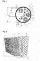
- an assembly 1 according to the first object of the invention comprises a tube 2 as well as five so-called “simplex” optical cables 6 and three multifiber optical cables 4.
- the tube 2 comprises a main layer 3 made of a first polymer material comprising a polyetherimide siloxane copolymer, and an inner layer 5 made of a second polymer material comprising a fluorinated polymer.
- a space 8 between the optical cables 4 and 6 is filled with air.
- the multifiber optical cables 4 include a protective casing 12 surrounding a central part 15.
- the casing 12 includes a protective sheath 14 made of a third polymer material comprising a copolymer of ethylene and fluorinated propylene.
- the envelope 12 also includes a textile screen 13 placed between a central part 15 and the protective sheath 14.
- the central part 15 comprises twelve optical fibers 16 which are surrounded by gel 17.
- the so-called “simplex” optical cables 6 comprise an envelope 12' comprising a textile screen 13' and a protective sheath 14' and a central part 15' comprising a single optical fiber 16'.
- the tube 2 has an internal diameter D with a value of 6 mm.
- the multifiber optical cables 4 have an outer diameter d1 with a value of 2 mm and the simplex optical cables 6 have an outer diameter d2 with a value of 0.9 mm.
- the d1/D ratio is therefore 0.33 and the d2/D ratio is therefore 0.15.
- the picture 2 illustrates a network 20 comprising an assembly 24 according to a second embodiment of the invention placed on a wall 22.
- the assembly 24 comprises the tube 2 with a length of 25 m as well as a single multifiber optical cable 4 not visible .
- the tube 2 is formed by extrusion from a polypropylene polymer.
- the multifiber optical cable 4 is installed in the tube 2 previously installed on the wall 22.
- the optical cable could be slid into the tube 2 from the input 28 over a length of 15 meters, and this, without the optical cable being damaged.
Landscapes
- Physics & Mathematics (AREA)
- General Physics & Mathematics (AREA)
- Optics & Photonics (AREA)
- Light Guides In General And Applications Therefor (AREA)
- Rigid Pipes And Flexible Pipes (AREA)
- Laying Of Electric Cables Or Lines Outside (AREA)
- Details Of Indoor Wiring (AREA)
Applications Claiming Priority (1)
| Application Number | Priority Date | Filing Date | Title |
|---|---|---|---|
| FR2014106A FR3118206B1 (fr) | 2020-12-23 | 2020-12-23 | Réseau de tubes pour câbles optiques |
Publications (1)
| Publication Number | Publication Date |
|---|---|
| EP4020050A1 true EP4020050A1 (de) | 2022-06-29 |
Family
ID=76522989
Family Applications (1)
| Application Number | Title | Priority Date | Filing Date |
|---|---|---|---|
| EP21217217.5A Pending EP4020050A1 (de) | 2020-12-23 | 2021-12-23 | Rohrnetz für optische kabel |
Country Status (4)
| Country | Link |
|---|---|
| US (1) | US11927824B2 (de) |
| EP (1) | EP4020050A1 (de) |
| CN (1) | CN114740577A (de) |
| FR (1) | FR3118206B1 (de) |
Families Citing this family (1)
| Publication number | Priority date | Publication date | Assignee | Title |
|---|---|---|---|---|
| FR3118204B1 (fr) * | 2020-12-23 | 2023-11-03 | Nexans | Réseau de tubes pour câbles optiques |
Citations (5)
| Publication number | Priority date | Publication date | Assignee | Title |
|---|---|---|---|---|
| US20040208463A1 (en) * | 2003-04-15 | 2004-10-21 | Kyung-Tae Park | Cable for use in an air blowing installation and apparatus for manufacturing the same |
| US20060018611A1 (en) * | 2004-07-22 | 2006-01-26 | Maida John L Jr | Method and system for providing a hydrogen diffusion barrier for fiber optic cables used in hostile environments |
| US20070183726A1 (en) * | 2006-02-08 | 2007-08-09 | Draka Comteq B.V. | Optical Fiber Cable Suited for Blown Installation or Pushing Installation in Microducts of Small Diameter |
| EP1818703A1 (de) | 2006-02-08 | 2007-08-15 | Draka Comteq B.V. | Glasfaserkabel für Blasinstallation oder Drückinstallation in Mikrokanälen mit kleinem Durchmesser |
| WO2019126303A1 (en) * | 2017-12-19 | 2019-06-27 | Commscope Technologies Llc | Protective tube for micro-duct installation of fiber optic cable |
Family Cites Families (20)
| Publication number | Priority date | Publication date | Assignee | Title |
|---|---|---|---|---|
| US4595793A (en) * | 1983-07-29 | 1986-06-17 | At&T Technologies, Inc. | Flame-resistant plenum cable and methods of making |
| US4892442A (en) * | 1987-03-03 | 1990-01-09 | Dura-Line | Prelubricated innerduct |
| CA2257295C (en) * | 1996-09-19 | 2002-12-31 | British Telecommunications Public Limited Company | Blowing head |
| FR2774521B1 (fr) * | 1998-02-04 | 2000-03-31 | France Telecom | Procede d'installation et/ou de retrait d'un cable dans des conduites de passage de cables et dispositif de mise en oeuvre |
| US6262371B1 (en) * | 1999-06-23 | 2001-07-17 | Marc Talon, Inc. | Method and apparatus for dividing a conduit into compartments |
| ES2311610T3 (es) * | 2001-06-04 | 2009-02-16 | Prysmian S.P.A. | Cable optico parovisto de recubrimiento resistente mecanicamente. |
| US6853781B2 (en) * | 2001-08-13 | 2005-02-08 | Sumitomo Electric Lightwave Corp. | Air blown fiber (ABF) cable with low composite coefficient of thermal expansion |
| US7182104B2 (en) * | 2002-02-20 | 2007-02-27 | Arnco Corporation | Collapsible duct |
| US6912347B2 (en) * | 2002-11-15 | 2005-06-28 | Alcatel | Optimized fiber optic cable suitable for microduct blown installation |
| GB0303879D0 (en) * | 2003-02-20 | 2003-03-26 | Emtelle Uk Ltd | Method of installing cables |
| US20050194578A1 (en) * | 2004-03-03 | 2005-09-08 | Morris David D. | Innerduct guide tube assembly for fiber optic cable |
| JP2006235263A (ja) * | 2005-02-25 | 2006-09-07 | Fuji Photo Film Co Ltd | 光ファイバケーブルの通線方法 |
| EP2031719B1 (de) * | 2007-08-31 | 2013-01-23 | Draka Comteq B.V. | Modifizierte abgeschirmte Kommunikationskabelanordnung und Installationsverfahren dafür |
| FR2931254B1 (fr) * | 2008-05-13 | 2015-05-01 | Draka Comteq France Sa | Procede d'installation d'un cable de telecommunication a fibres optiques |
| ES2819026T3 (es) * | 2010-09-10 | 2021-04-14 | Prysmian Spa | Cable óptico resistente al fuego |
| CN103513377A (zh) * | 2013-09-27 | 2014-01-15 | 江苏亨通光电股份有限公司 | 超微型气吹光缆 |
| CN204882964U (zh) * | 2015-04-09 | 2015-12-16 | 河北光城通信科技有限公司 | 全介质气吹微缆 |
| CN108241194A (zh) * | 2016-12-26 | 2018-07-03 | 东莞市金羽丰知识产权服务有限公司 | 采用导电纳米流体的耐拉型系留光缆 |
| US11243365B2 (en) | 2018-11-16 | 2022-02-08 | The Boeing Company | Methods for providing flammability protection for plastic optical fiber |
| CN109298495A (zh) * | 2018-12-03 | 2019-02-01 | 江苏中天科技股份有限公司 | 基于光纤束结构的大芯数气吹微缆 |
-
2020
- 2020-12-23 FR FR2014106A patent/FR3118206B1/fr active Active
-
2021
- 2021-12-23 US US17/560,649 patent/US11927824B2/en active Active
- 2021-12-23 CN CN202111589607.4A patent/CN114740577A/zh active Pending
- 2021-12-23 EP EP21217217.5A patent/EP4020050A1/de active Pending
Patent Citations (5)
| Publication number | Priority date | Publication date | Assignee | Title |
|---|---|---|---|---|
| US20040208463A1 (en) * | 2003-04-15 | 2004-10-21 | Kyung-Tae Park | Cable for use in an air blowing installation and apparatus for manufacturing the same |
| US20060018611A1 (en) * | 2004-07-22 | 2006-01-26 | Maida John L Jr | Method and system for providing a hydrogen diffusion barrier for fiber optic cables used in hostile environments |
| US20070183726A1 (en) * | 2006-02-08 | 2007-08-09 | Draka Comteq B.V. | Optical Fiber Cable Suited for Blown Installation or Pushing Installation in Microducts of Small Diameter |
| EP1818703A1 (de) | 2006-02-08 | 2007-08-15 | Draka Comteq B.V. | Glasfaserkabel für Blasinstallation oder Drückinstallation in Mikrokanälen mit kleinem Durchmesser |
| WO2019126303A1 (en) * | 2017-12-19 | 2019-06-27 | Commscope Technologies Llc | Protective tube for micro-duct installation of fiber optic cable |
Also Published As
| Publication number | Publication date |
|---|---|
| FR3118206A1 (fr) | 2022-06-24 |
| CN114740577A (zh) | 2022-07-12 |
| US20220252819A1 (en) | 2022-08-11 |
| FR3118206B1 (fr) | 2024-03-15 |
| US11927824B2 (en) | 2024-03-12 |
Similar Documents
| Publication | Publication Date | Title |
|---|---|---|
| US9857540B2 (en) | Strain relief boot and fiber optic cable assembly including the same | |
| EP0937270B1 (de) | Optisches nachrichtenkabel | |
| FR2564988A1 (fr) | Cable a fibres optiques | |
| NL2009684C2 (en) | An optical fiber cable. | |
| WO2004070446A1 (fr) | Cable a fibres optiques avec gaine de maintien | |
| US20090087148A1 (en) | Optical fiber cables | |
| FR2939911A1 (fr) | Fibre optique gainee, cable de telecommunication comportant plusieurs fibres optiques et procede de fabrication d'une telle fibre | |
| FR2908895A1 (fr) | Cables lisses et multilignes a rapport resistance/poids eleve | |
| FR2904699A1 (fr) | Gainage ameliore pour enrober une fibre optique dans un cable | |
| FR2757642A1 (fr) | Cable a fibres optiques a structure dissymetrique | |
| EP3521880B1 (de) | Glasfaserkabelanordnung | |
| EP4020050A1 (de) | Rohrnetz für optische kabel | |
| JP2019112293A (ja) | 高いシステム光信号対雑音比性能及び非線形性損失による低い劣化を必要とするアプリケーションのための光ファイバ | |
| US6859592B2 (en) | Optical fiber cable with controlled helix values | |
| FR2728694A1 (fr) | Module pour cables a fibres optiques, procede de fabrication et installation a cet effet | |
| FR2753543A1 (fr) | Cable a fibres optiques aerien | |
| EP0637768A1 (de) | Optisches Kabel und Herstellungsverfahren desselben | |
| US20110200291A1 (en) | Cable with multiple jackets and transition elements and assemblies therefor | |
| EP0703479A1 (de) | Faseroptisches Kabel | |
| EP4020049A1 (de) | Rohrnetz für optische kabel | |
| CN113267845A (zh) | 塑料光纤、塑料光纤线缆、带有连接器的塑料光纤线缆、光通信系统、和塑料光纤传感器 | |
| US12019281B2 (en) | Sealed optical cable assemblies and methods of fabricating the same | |
| CN1950735A (zh) | 缓冲光波导管 | |
| FR2958786A3 (fr) | Cable geophysique comprenant une gaine exterieure integrant au moins un renfort en fibre de verre enduit | |
| US12158615B2 (en) | Fiber-optic splice and method for producing a fiber-optic splice |
Legal Events
| Date | Code | Title | Description |
|---|---|---|---|
| PUAI | Public reference made under article 153(3) epc to a published international application that has entered the european phase |
Free format text: ORIGINAL CODE: 0009012 |
|
| STAA | Information on the status of an ep patent application or granted ep patent |
Free format text: STATUS: THE APPLICATION HAS BEEN PUBLISHED |
|
| AK | Designated contracting states |
Kind code of ref document: A1 Designated state(s): AL AT BE BG CH CY CZ DE DK EE ES FI FR GB GR HR HU IE IS IT LI LT LU LV MC MK MT NL NO PL PT RO RS SE SI SK SM TR |
|
| STAA | Information on the status of an ep patent application or granted ep patent |
Free format text: STATUS: REQUEST FOR EXAMINATION WAS MADE |
|
| 17P | Request for examination filed |
Effective date: 20230102 |
|
| RBV | Designated contracting states (corrected) |
Designated state(s): AL AT BE BG CH CY CZ DE DK EE ES FI FR GB GR HR HU IE IS IT LI LT LU LV MC MK MT NL NO PL PT RO RS SE SI SK SM TR |
|
| STAA | Information on the status of an ep patent application or granted ep patent |
Free format text: STATUS: EXAMINATION IS IN PROGRESS |
|
| 17Q | First examination report despatched |
Effective date: 20241218 |