EP0637768A1 - Optisches Kabel und Herstellungsverfahren desselben - Google Patents
Optisches Kabel und Herstellungsverfahren desselben Download PDFInfo
- Publication number
- EP0637768A1 EP0637768A1 EP94401773A EP94401773A EP0637768A1 EP 0637768 A1 EP0637768 A1 EP 0637768A1 EP 94401773 A EP94401773 A EP 94401773A EP 94401773 A EP94401773 A EP 94401773A EP 0637768 A1 EP0637768 A1 EP 0637768A1
- Authority
- EP
- European Patent Office
- Prior art keywords
- optical
- optical fibers
- fiber
- cable
- cable according
- Prior art date
- Legal status (The legal status is an assumption and is not a legal conclusion. Google has not performed a legal analysis and makes no representation as to the accuracy of the status listed.)
- Granted
Links
Images

Classifications
-
- G—PHYSICS
- G02—OPTICS
- G02B—OPTICAL ELEMENTS, SYSTEMS OR APPARATUS
- G02B6/00—Light guides; Structural details of arrangements comprising light guides and other optical elements, e.g. couplings
- G02B6/44—Mechanical structures for providing tensile strength and external protection for fibres, e.g. optical transmission cables
- G02B6/4479—Manufacturing methods of optical cables
- G02B6/4482—Code or colour marking
Definitions
- the present invention relates to a fiber optic cable, in particular for a distribution network. It also relates to an associated production process.
- Fiber optic cables allow information to be transmitted in excellent conditions and over ever greater distances.
- a first type of fiber optic cables is of the so-called honeycomb or free structure, that is to say it comprises one or more elements in the form of a grooved rod or tube in which the optical fibers are housed.
- the optical fibers are left free and with a certain excess length in the grooves or in the tube.
- a second type of optical fiber cables is of so-called ribbon structure, that is to say that the optical fibers are arranged parallel to each other and held together in a protective coating of resin.
- This type of cables is more compact and less bulky, because the use of extra lengths is not necessary.
- the ribbon structure is more suited to a global connection, which can cause problems in a distribution network. In fact, in a distribution network, it is necessary to be able to constantly change the topology, which requires the ribbon to burst and is hardly compatible with the constraints of the global connection, which is too inflexible.
- the object of the present invention is to remedy these drawbacks by proposing a fiber optic cable which meets the constraints inherent in use in a distribution network, can be produced at low cost, allows ease of connection and can include a number high in fiber.
- the invention provides a fiber optic cable comprising a plurality of optical fibers, each comprising an optical core surrounded by an optical sheath, each of said optical fibers being provided above said optical sheath with a substantially hermetic coating. and comprising above said hermetic covering a covering made of a plastic material, said cable further comprising an outer protective sheath made of a plastic material surrounding said optical fibers, characterized in that each of said optical fibers has a mode field diameter of between 7 and 9 ⁇ m around 1550 nm, and a cut-off wavelength less than or equal to 1.35 ⁇ m, and in that said optical fibers are assembled in said cable by being twisted together or around a reinforcing element, or arranged lengthwise.
- curvatures and the micro-curvatures cause for the optical fibers which are subjected to it a reduction in their lifespan as well as an increase in transmission losses due to an increase in attenuation.
- optical fibers With a thin hermetic coating (which therefore does not increase its size), their lifespan is increased and the first consequence of the bends and micro-bends is therefore avoided.
- optical fibers have thus been reduced, which avoids having to use extra lengths and free structures. It is thus possible to use optical fibers in structures of the type of those used for electrical distribution cables, which ensure a high compactness compared to that of fiber optic cables with free structure, while allowing easy connections in comparison with cables to optical fibers in ribbons.
- the effects of the curvatures and the micro-curvatures are therefore reduced not by having recourse to structures of large diameter or to ribbon structures, but by acting directly on the optical fiber.
- the combination of the new structure of optical fiber with a cable structure of the type used in electrical distribution, authorized by the increased resistance of optical fiber to bends and micro-bends, results in a particularly space-saving cable suitable for use in distribution networks, as are electrical cables with the same structure.
- the mode field diameter of the fibers of a cable is between 7 and 9 ⁇ m around 1550 nm, and the cut-off wavelength of each of the fibers is less or equal to 1.35 ⁇ m, and preferably close to 1.33 ⁇ m.
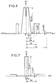
- Two non-limiting examples of index profiles enabling this characteristic to be obtained are shown in FIGS. 6 and 7, where the difference ⁇ n between the refractive indices of the different parts of the optical fiber and that of the cladding immediately surrounding the core is given as a function of the distance d to the axis of the fiber, a being the radius of the core of the optical fiber.
- an optical fiber 1 used in a cable according to the invention has previously been subjected, on its optical silica sheath 2 which conventionally surrounds an optical propagation core 3, to a treatment 4, which can consist of a surface treatment for example based on titanium oxide or the addition of a coating layer for example of carbon, this treatment being intended to increase the life of the fiber.
- a treatment 4 which can consist of a surface treatment for example based on titanium oxide or the addition of a coating layer for example of carbon, this treatment being intended to increase the life of the fiber.
- the above coating is very thin, for example around 0.5 ⁇ m.
- optical sheath All the possible layers of silica surrounding the optical core are called “optical sheath” and generally bear the reference number 2, to simplify the description.
- optical cladding can be complex (in particular as illustrated in FIGS. 6 and 7) in order to obtain the desired properties, and does not necessarily consist of a single layer of silica around the optical core.
- a plastic coating 5 is produced on the previously treated fiber.
- the purpose of this coating is to protect treatment 4; it also makes it possible to contribute to the identification by color codes of the different fibers within a cable. This identification is essential for cables used in a distribution network. It can be made by coating or preferably by extrusion to have a greater possibility of color combinations.
- a first assembly method well known in the field of electric cables is said to have concentric layers and is represented in FIG. 2.
- the fibers 1, 22 are arranged in a helix (or twisted) within 'a cable 20 regularly in concentric layers for example around a mechanical reinforcement element 21 which can be made of stuffing material.
- This reinforcing element 21 can be replaced by an optical fiber.
- the fibers are arranged within a cable 30 in bundles 31, 32, 33, each bundle itself being arranged in various ways, for example in concentric or long layers.
- This assembly is protected by an outer sheath 34 of plastic material.
- FIG. 4 illustrates in a simplified way the structure of a fiber 40 comprising four hearts 43, 45, 46, 47, a treatment 44 and a plastic coating 45.
- the fibers or fiber bundles are usually twisted along the length of the cable, either according to a helical assembly mode 52 with reference to FIG. 5B illustrating a cable 55 comprising fibers 1 treated according to invention, either according to an assembly method of the so-called SZ 51 type with reference to FIG. 5A illustrating a cable 50 comprising fibers 1 treated according to the invention.
- the optical fibers can be assembled in a tight structure or not, and lengthwise, optionally around a central reinforcing element.
- the plastic coating produced on the treated fiber must have the smallest possible thickness in order to minimize the bulk and increase the number of fibers in a cable of given diameter.
- This plastic coating has a dual treatment protection function made on the outer silica layer of the fiber and identified by an appropriate color code. This identification function is essential for cables used in a distribution network.
- the extrusion coating technique makes it easy to color label the plastic coating. It should be noted that the coating technique using a resin is less suitable for carrying out identification by multiple color codes.
- the number and the assembly of the fibers within a cable can be arbitrary and depend in particular on the operating conditions of this cable.
Landscapes
- Physics & Mathematics (AREA)
- Engineering & Computer Science (AREA)
- Manufacturing & Machinery (AREA)
- General Physics & Mathematics (AREA)
- Optics & Photonics (AREA)
- Optical Fibers, Optical Fiber Cores, And Optical Fiber Bundles (AREA)
- Surface Treatment Of Glass Fibres Or Filaments (AREA)
- Communication Cables (AREA)
- Manufacture, Treatment Of Glass Fibers (AREA)
- Ropes Or Cables (AREA)
Applications Claiming Priority (2)
| Application Number | Priority Date | Filing Date | Title |
|---|---|---|---|
| FR9309615 | 1993-08-04 | ||
| FR9309615A FR2708754B1 (fr) | 1993-08-04 | 1993-08-04 | Câble à fibres optiques et procédé de réalisation associé. |
Publications (2)
| Publication Number | Publication Date |
|---|---|
| EP0637768A1 true EP0637768A1 (de) | 1995-02-08 |
| EP0637768B1 EP0637768B1 (de) | 1999-10-06 |
Family
ID=9449941
Family Applications (1)
| Application Number | Title | Priority Date | Filing Date |
|---|---|---|---|
| EP94401773A Expired - Lifetime EP0637768B1 (de) | 1993-08-04 | 1994-08-02 | Optischer Faser,optisches Kabel und Herstellungsverfahren desselben |
Country Status (8)
| Country | Link |
|---|---|
| US (2) | US5590233A (de) |
| EP (1) | EP0637768B1 (de) |
| JP (1) | JPH0763930A (de) |
| CN (1) | CN1124354A (de) |
| AT (1) | ATE185427T1 (de) |
| CA (1) | CA2129294A1 (de) |
| DE (1) | DE69421019T2 (de) |
| FR (1) | FR2708754B1 (de) |
Families Citing this family (15)
| Publication number | Priority date | Publication date | Assignee | Title |
|---|---|---|---|---|
| FR2725041B1 (fr) * | 1994-09-23 | 1996-11-22 | Alcatel Cable | Cable a fibres optiques |
| US5703983A (en) * | 1996-12-04 | 1997-12-30 | Sumitomo Electric Lightwave Corp. | S-Z stranded optical cable with mid-span entry marker |
| US6151336A (en) | 1998-02-11 | 2000-11-21 | Sorrento Networks, Inc. | Time division multiplexing expansion subsystem |
| US6400478B1 (en) | 1998-04-02 | 2002-06-04 | Sorrento Networks, Inc. | Wavelength-division-multiplexed optical transmission system with expanded bidirectional transmission capacity over a single fiber |
| US6298103B1 (en) | 1998-06-16 | 2001-10-02 | Sorrento Networks Corporation | Flexible clock and data recovery module for a DWDM optical communication system with multiple clock rates |
| US6292615B1 (en) | 1999-03-09 | 2001-09-18 | Uniphase Telecommunications Products, Inc. | Optical fiber feedthrough |
| US6477297B1 (en) * | 2000-03-08 | 2002-11-05 | Corning Incorporated | Reduction of bend loss through constraint of optical fiber parameters |
| FR2871796B1 (fr) * | 2004-06-21 | 2006-09-15 | Alcatel Sa | Procede et installation de fabrication d'un element fibre a filtre de lumiere selectif |
| US8515278B2 (en) * | 2008-10-31 | 2013-08-20 | Futurewei Technologies, Inc. | Passive optical networks with mode coupling receivers |
| BRPI0823227A2 (pt) * | 2008-11-07 | 2019-02-26 | Prysmian Spa | cabo óptico, e, rede de distribuição de acesso |
| US9110263B2 (en) * | 2009-11-19 | 2015-08-18 | Acrylicom Ltd. | System and method for aligning a multi-core plastic optical fiber assembly |
| US8885999B2 (en) | 2010-03-19 | 2014-11-11 | Corning Cable Systems Llc | Optical USB cable with controlled fiber positioning |
| US10107983B2 (en) * | 2016-04-29 | 2018-10-23 | Corning Optical Communications LLC | Preferential mode coupling for enhanced traceable patch cord performance |
| US11480749B2 (en) * | 2020-04-14 | 2022-10-25 | The United States Of America, As Represented By The Secretary Of The Navy | Multicore fiber optic cable |
| JP2024158542A (ja) * | 2023-04-27 | 2024-11-08 | 日本ピー・アイ株式会社 | 光源内蔵型の多波長近赤外線照射装置。 |
Citations (6)
| Publication number | Priority date | Publication date | Assignee | Title |
|---|---|---|---|---|
| GB2109581A (en) * | 1981-11-12 | 1983-06-02 | Standard Telephones Cables Ltd | Colour coding optic fibres |
| JPS61113007A (ja) * | 1984-11-08 | 1986-05-30 | Nippon Telegr & Teleph Corp <Ntt> | 光フアイバ |
| EP0245752A2 (de) * | 1986-05-10 | 1987-11-19 | Sumitomo Electric Industries Limited | Fiberidentifikation in einer geerdeten Freileitung mit optischen Fibern |
| JPH0247613A (ja) * | 1988-08-09 | 1990-02-16 | Fujikura Ltd | 光ファイバテープ心線 |
| EP0402895A1 (de) * | 1989-06-13 | 1990-12-19 | Sumitomo Electric Industries, Ltd. | Hermetisch ummantelte optische Fasern und Herstellung dieser Fasern |
| EP0432931A1 (de) * | 1989-12-13 | 1991-06-19 | AT&T Corp. | Optische Faser mit einer gefärbten, ausgehärteten, pigmentlosen Beschichtung |
Family Cites Families (19)
| Publication number | Priority date | Publication date | Assignee | Title |
|---|---|---|---|---|
| US3775075A (en) * | 1972-01-03 | 1973-11-27 | Corning Glass Works | Method of forming optical waveguide fibers |
| JPS51954A (en) * | 1974-06-21 | 1976-01-07 | Hitachi Ltd | Hikaridensoyosenro oyobi sonoseizohoho |
| JPS51127743A (en) * | 1975-04-30 | 1976-11-08 | Nippon Telegr & Teleph Corp <Ntt> | Optical fiber and its manufacturing method |
| US5183323A (en) * | 1982-09-29 | 1993-02-02 | Maurice Daniel | Flat panel illumination system |
| US5021928A (en) * | 1982-09-29 | 1991-06-04 | Maurice Daniel | Flat panel illumination system |
| JPH0695167B2 (ja) * | 1986-03-04 | 1994-11-24 | 富士通株式会社 | 広波長域低分散シングルモ−ドフアイバ |
| US4874222A (en) * | 1986-03-31 | 1989-10-17 | Spectran Corporation | Hermetic coatings for non-silica based optical fibers |
| US4735856A (en) * | 1986-03-31 | 1988-04-05 | Spectran Corporation | Hermetic coatings for optical fiber and product |
| JPH0713688B2 (ja) * | 1987-01-16 | 1995-02-15 | 住友電気工業株式会社 | 光ファイバケーブル |
| US4844575A (en) * | 1987-04-10 | 1989-07-04 | American Telephone And Telegraph Company, At&T Bell Laboratories | Optical fiber cable |
| JP2572598B2 (ja) * | 1987-05-25 | 1997-01-16 | 株式会社フジクラ | 耐熱光ファイバユニット |
| US4877306A (en) * | 1987-09-30 | 1989-10-31 | Corning Glass Works | Coated optical waveguide fibers |
| JP2831363B2 (ja) * | 1988-11-22 | 1998-12-02 | 株式会社フジクラ | 光ファイバ |
| JPH0333703A (ja) * | 1989-06-29 | 1991-02-14 | Furukawa Electric Co Ltd:The | 光ファイバ |
| JPH06100702B2 (ja) * | 1989-07-21 | 1994-12-12 | 住友電気工業株式会社 | 光ファイバケーブルの製造方法 |
| JP3001117B2 (ja) * | 1990-05-28 | 2000-01-24 | 日本電信電話株式会社 | 光ケーブルとその製造方法 |
| JP2999609B2 (ja) * | 1991-10-08 | 2000-01-17 | 三菱電線工業株式会社 | カーボンコート光ファイバ心線 |
| JP2948952B2 (ja) * | 1991-07-10 | 1999-09-13 | 株式会社フジクラ | カーボンコート光ファイバ心線 |
| US5259060A (en) * | 1992-08-11 | 1993-11-02 | Corning Incorporated | Coated optical fibers and method |
-
1993
- 1993-08-04 FR FR9309615A patent/FR2708754B1/fr not_active Expired - Fee Related
-
1994
- 1994-08-02 CA CA002129294A patent/CA2129294A1/fr not_active Abandoned
- 1994-08-02 EP EP94401773A patent/EP0637768B1/de not_active Expired - Lifetime
- 1994-08-02 AT AT94401773T patent/ATE185427T1/de not_active IP Right Cessation
- 1994-08-02 DE DE69421019T patent/DE69421019T2/de not_active Expired - Lifetime
- 1994-08-03 US US08/285,287 patent/US5590233A/en not_active Expired - Lifetime
- 1994-08-04 CN CN94116192A patent/CN1124354A/zh active Pending
- 1994-08-04 JP JP6183762A patent/JPH0763930A/ja active Pending
- 1994-12-06 US US08/354,154 patent/US5544272A/en not_active Expired - Lifetime
Patent Citations (6)
| Publication number | Priority date | Publication date | Assignee | Title |
|---|---|---|---|---|
| GB2109581A (en) * | 1981-11-12 | 1983-06-02 | Standard Telephones Cables Ltd | Colour coding optic fibres |
| JPS61113007A (ja) * | 1984-11-08 | 1986-05-30 | Nippon Telegr & Teleph Corp <Ntt> | 光フアイバ |
| EP0245752A2 (de) * | 1986-05-10 | 1987-11-19 | Sumitomo Electric Industries Limited | Fiberidentifikation in einer geerdeten Freileitung mit optischen Fibern |
| JPH0247613A (ja) * | 1988-08-09 | 1990-02-16 | Fujikura Ltd | 光ファイバテープ心線 |
| EP0402895A1 (de) * | 1989-06-13 | 1990-12-19 | Sumitomo Electric Industries, Ltd. | Hermetisch ummantelte optische Fasern und Herstellung dieser Fasern |
| EP0432931A1 (de) * | 1989-12-13 | 1991-06-19 | AT&T Corp. | Optische Faser mit einer gefärbten, ausgehärteten, pigmentlosen Beschichtung |
Non-Patent Citations (3)
| Title |
|---|
| LIANG AN-HUI: "microbending losses for weakly guiding single-mode fibers", IEEE JOURNAL OF QUANTUM ELECTRONICS, vol. 28, no. 6, 6 June 1992 (1992-06-06), NEW YORK US, pages 1429 - 1434 * |
| PATENT ABSTRACTS OF JAPAN vol. 10, no. 294 (P - 504) 7 October 1986 (1986-10-07) * |
| PATENT ABSTRACTS OF JAPAN vol. 14, no. 214 (P - 1044) 7 May 1990 (1990-05-07) * |
Also Published As
| Publication number | Publication date |
|---|---|
| ATE185427T1 (de) | 1999-10-15 |
| JPH0763930A (ja) | 1995-03-10 |
| US5544272A (en) | 1996-08-06 |
| CN1124354A (zh) | 1996-06-12 |
| FR2708754B1 (fr) | 1995-09-08 |
| EP0637768B1 (de) | 1999-10-06 |
| DE69421019D1 (de) | 1999-11-11 |
| FR2708754A1 (fr) | 1995-02-10 |
| CA2129294A1 (fr) | 1995-02-05 |
| US5590233A (en) | 1996-12-31 |
| DE69421019T2 (de) | 2000-05-25 |
Similar Documents
| Publication | Publication Date | Title |
|---|---|---|
| EP0637768B1 (de) | Optischer Faser,optisches Kabel und Herstellungsverfahren desselben | |
| NL2009684C2 (en) | An optical fiber cable. | |
| CA2047842C (fr) | Cable de telecommunication | |
| EP0864896B1 (de) | Optische Einheit für ein Faseroptischeskabel | |
| EP0769711A1 (de) | Optische Baueinheit für ein faseroptisches Nachrichtenkabel und faseroptisches Kabel mit einer derartigen Baueinheit | |
| WO2004070446A1 (fr) | Cable a fibres optiques avec gaine de maintien | |
| CA1085204A (fr) | Cable a fibres optiques et procede de realisation | |
| FR2564988A1 (fr) | Cable a fibres optiques | |
| EP0696750B1 (de) | Herstellungsverfahren für ein verstärktes faseroptisches Kabel, zugehörige Vorrichtung und Kabel mittels diesem Verfahren gefertigt | |
| EP0703479A1 (de) | Faseroptisches Kabel | |
| FR2744809A1 (fr) | Cable a fibres optiques sans elements de renfort | |
| EP1972977A1 (de) | Optisches Kabel zum Anschluss an ein allgemeines Verteilernetz und Anschlussverfahren dieses Kabels | |
| FR2728693A1 (fr) | Procede de fabrication d'un repartiteur optique multifibre et repartiteur optique obtenu selon ce procede | |
| FR2672699A1 (fr) | Ruban de fibres optiques. | |
| EP0571279A1 (de) | Multifaser-Kabelelement | |
| FR2633092A1 (fr) | Cable electrique de transport d'energie incorporant une ou plusieurs fibres optiques | |
| EP0060180A1 (de) | Kabelelement und faseroptisches Kabel, hauptsächlich widerstandsfähig gegen erhöhte Zug- und/oder Druckkräfte, und zugehöriges Herstellungsverfahren | |
| EP0718647B1 (de) | Optische Einmodenfaser | |
| FR2914752A1 (fr) | Cable de telecommunication a fibres optiques | |
| FR2803666A1 (fr) | Cable optique adapte au(x) piquage(s) | |
| EP0544595B1 (de) | Mehradriges optisches Kabel und Verfahren zu seiner Herstellung | |
| BE898103A (fr) | Cable à fibres optiques. | |
| EP0570268A1 (de) | Herstellungsverfahren für ein optisches Einkanalkabel sowie für ein gemischtes, spiralförmiges Kabel, Einkanalkabel und gemischtes spiralförmiges Kabel nach diesem Herstellungsverfahren | |
| NZ616910B (en) | An optical fiber cable | |
| WO1997025643A1 (fr) | Ruban a fibres optiques et procede de realisation |
Legal Events
| Date | Code | Title | Description |
|---|---|---|---|
| PUAI | Public reference made under article 153(3) epc to a published international application that has entered the european phase |
Free format text: ORIGINAL CODE: 0009012 |
|
| AK | Designated contracting states |
Kind code of ref document: A1 Designated state(s): AT BE CH DE DK ES FR GB IE IT LI NL SE |
|
| 17P | Request for examination filed |
Effective date: 19950629 |
|
| 17Q | First examination report despatched |
Effective date: 19960131 |
|
| GRAG | Despatch of communication of intention to grant |
Free format text: ORIGINAL CODE: EPIDOS AGRA |
|
| GRAG | Despatch of communication of intention to grant |
Free format text: ORIGINAL CODE: EPIDOS AGRA |
|
| GRAH | Despatch of communication of intention to grant a patent |
Free format text: ORIGINAL CODE: EPIDOS IGRA |
|
| GRAH | Despatch of communication of intention to grant a patent |
Free format text: ORIGINAL CODE: EPIDOS IGRA |
|
| GRAA | (expected) grant |
Free format text: ORIGINAL CODE: 0009210 |
|
| RAP1 | Party data changed (applicant data changed or rights of an application transferred) |
Owner name: ALCATEL |
|
| AK | Designated contracting states |
Kind code of ref document: B1 Designated state(s): AT BE CH DE DK ES FR GB IE IT LI NL SE |
|
| PG25 | Lapsed in a contracting state [announced via postgrant information from national office to epo] |
Ref country code: NL Free format text: LAPSE BECAUSE OF FAILURE TO SUBMIT A TRANSLATION OF THE DESCRIPTION OR TO PAY THE FEE WITHIN THE PRESCRIBED TIME-LIMIT Effective date: 19991006 Ref country code: ES Free format text: THE PATENT HAS BEEN ANNULLED BY A DECISION OF A NATIONAL AUTHORITY Effective date: 19991006 Ref country code: AT Free format text: LAPSE BECAUSE OF FAILURE TO SUBMIT A TRANSLATION OF THE DESCRIPTION OR TO PAY THE FEE WITHIN THE PRESCRIBED TIME-LIMIT Effective date: 19991006 |
|
| REF | Corresponds to: |
Ref document number: 185427 Country of ref document: AT Date of ref document: 19991015 Kind code of ref document: T |
|
| REG | Reference to a national code |
Ref country code: CH Ref legal event code: EP |
|
| REF | Corresponds to: |
Ref document number: 69421019 Country of ref document: DE Date of ref document: 19991111 |
|
| ITF | It: translation for a ep patent filed | ||
| GBT | Gb: translation of ep patent filed (gb section 77(6)(a)/1977) |
Effective date: 19991116 |
|
| PG25 | Lapsed in a contracting state [announced via postgrant information from national office to epo] |
Ref country code: DK Free format text: LAPSE BECAUSE OF FAILURE TO SUBMIT A TRANSLATION OF THE DESCRIPTION OR TO PAY THE FEE WITHIN THE PRESCRIBED TIME-LIMIT Effective date: 20000106 |
|
| REG | Reference to a national code |
Ref country code: IE Ref legal event code: FG4D Free format text: FRENCH |
|
| NLV1 | Nl: lapsed or annulled due to failure to fulfill the requirements of art. 29p and 29m of the patents act | ||
| PLBE | No opposition filed within time limit |
Free format text: ORIGINAL CODE: 0009261 |
|
| STAA | Information on the status of an ep patent application or granted ep patent |
Free format text: STATUS: NO OPPOSITION FILED WITHIN TIME LIMIT |
|
| PG25 | Lapsed in a contracting state [announced via postgrant information from national office to epo] |
Ref country code: LI Free format text: LAPSE BECAUSE OF NON-PAYMENT OF DUE FEES Effective date: 20000831 Ref country code: CH Free format text: LAPSE BECAUSE OF NON-PAYMENT OF DUE FEES Effective date: 20000831 Ref country code: BE Free format text: LAPSE BECAUSE OF NON-PAYMENT OF DUE FEES Effective date: 20000831 |
|
| 26N | No opposition filed | ||
| PG25 | Lapsed in a contracting state [announced via postgrant information from national office to epo] |
Ref country code: IE Free format text: LAPSE BECAUSE OF NON-PAYMENT OF DUE FEES Effective date: 20001109 |
|
| REG | Reference to a national code |
Ref country code: IE Ref legal event code: FD4D |
|
| BERE | Be: lapsed |
Owner name: ALCATEL Effective date: 20000831 |
|
| REG | Reference to a national code |
Ref country code: CH Ref legal event code: PL |
|
| PGFP | Annual fee paid to national office [announced via postgrant information from national office to epo] |
Ref country code: SE Payment date: 20010802 Year of fee payment: 8 |
|
| REG | Reference to a national code |
Ref country code: GB Ref legal event code: IF02 |
|
| PG25 | Lapsed in a contracting state [announced via postgrant information from national office to epo] |
Ref country code: SE Free format text: LAPSE BECAUSE OF NON-PAYMENT OF DUE FEES Effective date: 20020803 |
|
| EUG | Se: european patent has lapsed | ||
| PGFP | Annual fee paid to national office [announced via postgrant information from national office to epo] |
Ref country code: DE Payment date: 20130821 Year of fee payment: 20 |
|
| PGFP | Annual fee paid to national office [announced via postgrant information from national office to epo] |
Ref country code: GB Payment date: 20130821 Year of fee payment: 20 Ref country code: FR Payment date: 20130823 Year of fee payment: 20 |
|
| PGFP | Annual fee paid to national office [announced via postgrant information from national office to epo] |
Ref country code: IT Payment date: 20130828 Year of fee payment: 20 |
|
| REG | Reference to a national code |
Ref country code: DE Ref legal event code: R071 Ref document number: 69421019 Country of ref document: DE |
|
| REG | Reference to a national code |
Ref country code: DE Ref legal event code: R071 Ref document number: 69421019 Country of ref document: DE |
|
| REG | Reference to a national code |
Ref country code: GB Ref legal event code: PE20 Expiry date: 20140801 |
|
| PG25 | Lapsed in a contracting state [announced via postgrant information from national office to epo] |
Ref country code: DE Free format text: LAPSE BECAUSE OF EXPIRATION OF PROTECTION Effective date: 20140805 |
|
| PG25 | Lapsed in a contracting state [announced via postgrant information from national office to epo] |
Ref country code: GB Free format text: LAPSE BECAUSE OF EXPIRATION OF PROTECTION Effective date: 20140801 |