EP4021834B1 - Dispositif d'alimentation d'une machine de traitement de feuilles et procédé de détection et/ou de correction de feuilles divergentes en position et/ou en dimensions dans un dispositif d'alimentation d'une machine de traitement de feuilles - Google Patents
Dispositif d'alimentation d'une machine de traitement de feuilles et procédé de détection et/ou de correction de feuilles divergentes en position et/ou en dimensions dans un dispositif d'alimentation d'une machine de traitement de feuilles Download PDFInfo
- Publication number
- EP4021834B1 EP4021834B1 EP21729234.1A EP21729234A EP4021834B1 EP 4021834 B1 EP4021834 B1 EP 4021834B1 EP 21729234 A EP21729234 A EP 21729234A EP 4021834 B1 EP4021834 B1 EP 4021834B1
- Authority
- EP
- European Patent Office
- Prior art keywords
- stack
- transport direction
- sheets
- distance
- sensors
- Prior art date
- Legal status (The legal status is an assumption and is not a legal conclusion. Google has not performed a legal analysis and makes no representation as to the accuracy of the status listed.)
- Active
Links
Images



Classifications
-
- B—PERFORMING OPERATIONS; TRANSPORTING
- B65—CONVEYING; PACKING; STORING; HANDLING THIN OR FILAMENTARY MATERIAL
- B65H—HANDLING THIN OR FILAMENTARY MATERIAL, e.g. SHEETS, WEBS, CABLES
- B65H3/00—Separating articles from piles
- B65H3/08—Separating articles from piles using pneumatic force
- B65H3/0808—Suction grippers
- B65H3/0816—Suction grippers separating from the top of pile
-
- B—PERFORMING OPERATIONS; TRANSPORTING
- B65—CONVEYING; PACKING; STORING; HANDLING THIN OR FILAMENTARY MATERIAL
- B65H—HANDLING THIN OR FILAMENTARY MATERIAL, e.g. SHEETS, WEBS, CABLES
- B65H1/00—Supports or magazines for piles from which articles are to be separated
- B65H1/04—Supports or magazines for piles from which articles are to be separated adapted to support articles substantially horizontally, e.g. for separation from top of pile
-
- B—PERFORMING OPERATIONS; TRANSPORTING
- B65—CONVEYING; PACKING; STORING; HANDLING THIN OR FILAMENTARY MATERIAL
- B65H—HANDLING THIN OR FILAMENTARY MATERIAL, e.g. SHEETS, WEBS, CABLES
- B65H1/00—Supports or magazines for piles from which articles are to be separated
- B65H1/08—Supports or magazines for piles from which articles are to be separated with means for advancing the articles to present the articles to the separating device
- B65H1/14—Supports or magazines for piles from which articles are to be separated with means for advancing the articles to present the articles to the separating device comprising positively-acting mechanical devices
-
- B—PERFORMING OPERATIONS; TRANSPORTING
- B65—CONVEYING; PACKING; STORING; HANDLING THIN OR FILAMENTARY MATERIAL
- B65H—HANDLING THIN OR FILAMENTARY MATERIAL, e.g. SHEETS, WEBS, CABLES
- B65H3/00—Separating articles from piles
- B65H3/08—Separating articles from piles using pneumatic force
- B65H3/0808—Suction grippers
- B65H3/0816—Suction grippers separating from the top of pile
- B65H3/0825—Suction grippers separating from the top of pile and acting on the rear part of the articles relatively to the final separating direction
-
- B—PERFORMING OPERATIONS; TRANSPORTING
- B65—CONVEYING; PACKING; STORING; HANDLING THIN OR FILAMENTARY MATERIAL
- B65H—HANDLING THIN OR FILAMENTARY MATERIAL, e.g. SHEETS, WEBS, CABLES
- B65H3/00—Separating articles from piles
- B65H3/08—Separating articles from piles using pneumatic force
- B65H3/0808—Suction grippers
- B65H3/0883—Construction of suction grippers or their holding devices
-
- B—PERFORMING OPERATIONS; TRANSPORTING
- B65—CONVEYING; PACKING; STORING; HANDLING THIN OR FILAMENTARY MATERIAL
- B65H—HANDLING THIN OR FILAMENTARY MATERIAL, e.g. SHEETS, WEBS, CABLES
- B65H5/00—Feeding articles separated from piles; Feeding articles to machines
- B65H5/02—Feeding articles separated from piles; Feeding articles to machines by belts or chains, e.g. between belts or chains
- B65H5/021—Feeding articles separated from piles; Feeding articles to machines by belts or chains, e.g. between belts or chains by belts
-
- B—PERFORMING OPERATIONS; TRANSPORTING
- B65—CONVEYING; PACKING; STORING; HANDLING THIN OR FILAMENTARY MATERIAL
- B65H—HANDLING THIN OR FILAMENTARY MATERIAL, e.g. SHEETS, WEBS, CABLES
- B65H7/00—Controlling article feeding, separating, pile-advancing, or associated apparatus, to take account of incorrect feeding, absence of articles, or presence of faulty articles
- B65H7/02—Controlling article feeding, separating, pile-advancing, or associated apparatus, to take account of incorrect feeding, absence of articles, or presence of faulty articles by feelers or detectors
-
- B—PERFORMING OPERATIONS; TRANSPORTING
- B65—CONVEYING; PACKING; STORING; HANDLING THIN OR FILAMENTARY MATERIAL
- B65H—HANDLING THIN OR FILAMENTARY MATERIAL, e.g. SHEETS, WEBS, CABLES
- B65H7/00—Controlling article feeding, separating, pile-advancing, or associated apparatus, to take account of incorrect feeding, absence of articles, or presence of faulty articles
- B65H7/02—Controlling article feeding, separating, pile-advancing, or associated apparatus, to take account of incorrect feeding, absence of articles, or presence of faulty articles by feelers or detectors
- B65H7/06—Controlling article feeding, separating, pile-advancing, or associated apparatus, to take account of incorrect feeding, absence of articles, or presence of faulty articles by feelers or detectors responsive to presence of faulty articles or incorrect separation or feed
-
- B—PERFORMING OPERATIONS; TRANSPORTING
- B65—CONVEYING; PACKING; STORING; HANDLING THIN OR FILAMENTARY MATERIAL
- B65H—HANDLING THIN OR FILAMENTARY MATERIAL, e.g. SHEETS, WEBS, CABLES
- B65H7/00—Controlling article feeding, separating, pile-advancing, or associated apparatus, to take account of incorrect feeding, absence of articles, or presence of faulty articles
- B65H7/02—Controlling article feeding, separating, pile-advancing, or associated apparatus, to take account of incorrect feeding, absence of articles, or presence of faulty articles by feelers or detectors
- B65H7/06—Controlling article feeding, separating, pile-advancing, or associated apparatus, to take account of incorrect feeding, absence of articles, or presence of faulty articles by feelers or detectors responsive to presence of faulty articles or incorrect separation or feed
- B65H7/08—Controlling article feeding, separating, pile-advancing, or associated apparatus, to take account of incorrect feeding, absence of articles, or presence of faulty articles by feelers or detectors responsive to presence of faulty articles or incorrect separation or feed responsive to incorrect front register
-
- B—PERFORMING OPERATIONS; TRANSPORTING
- B65—CONVEYING; PACKING; STORING; HANDLING THIN OR FILAMENTARY MATERIAL
- B65H—HANDLING THIN OR FILAMENTARY MATERIAL, e.g. SHEETS, WEBS, CABLES
- B65H7/00—Controlling article feeding, separating, pile-advancing, or associated apparatus, to take account of incorrect feeding, absence of articles, or presence of faulty articles
- B65H7/20—Controlling associated apparatus
-
- B—PERFORMING OPERATIONS; TRANSPORTING
- B65—CONVEYING; PACKING; STORING; HANDLING THIN OR FILAMENTARY MATERIAL
- B65H—HANDLING THIN OR FILAMENTARY MATERIAL, e.g. SHEETS, WEBS, CABLES
- B65H9/00—Registering, e.g. orientating, articles; Devices therefor
- B65H9/10—Pusher and like movable registers; Pusher or gripper devices which move articles into registered position
- B65H9/103—Pusher and like movable registers; Pusher or gripper devices which move articles into registered position acting by friction or suction on the article for pushing or pulling it into registered position, e.g. against a stop
-
- B—PERFORMING OPERATIONS; TRANSPORTING
- B65—CONVEYING; PACKING; STORING; HANDLING THIN OR FILAMENTARY MATERIAL
- B65H—HANDLING THIN OR FILAMENTARY MATERIAL, e.g. SHEETS, WEBS, CABLES
- B65H2511/00—Dimensions; Position; Numbers; Identification; Occurrences
- B65H2511/20—Location in space
- B65H2511/22—Distance
-
- B—PERFORMING OPERATIONS; TRANSPORTING
- B65—CONVEYING; PACKING; STORING; HANDLING THIN OR FILAMENTARY MATERIAL
- B65H—HANDLING THIN OR FILAMENTARY MATERIAL, e.g. SHEETS, WEBS, CABLES
- B65H2511/00—Dimensions; Position; Numbers; Identification; Occurrences
- B65H2511/20—Location in space
- B65H2511/24—Irregularities, e.g. in orientation or skewness
-
- B—PERFORMING OPERATIONS; TRANSPORTING
- B65—CONVEYING; PACKING; STORING; HANDLING THIN OR FILAMENTARY MATERIAL
- B65H—HANDLING THIN OR FILAMENTARY MATERIAL, e.g. SHEETS, WEBS, CABLES
- B65H2511/00—Dimensions; Position; Numbers; Identification; Occurrences
- B65H2511/50—Occurence
- B65H2511/52—Defective operating conditions
-
- B—PERFORMING OPERATIONS; TRANSPORTING
- B65—CONVEYING; PACKING; STORING; HANDLING THIN OR FILAMENTARY MATERIAL
- B65H—HANDLING THIN OR FILAMENTARY MATERIAL, e.g. SHEETS, WEBS, CABLES
- B65H2515/00—Physical entities not provided for in groups B65H2511/00 or B65H2513/00
- B65H2515/30—Forces; Stresses
- B65H2515/34—Pressure, e.g. fluid pressure
-
- B—PERFORMING OPERATIONS; TRANSPORTING
- B65—CONVEYING; PACKING; STORING; HANDLING THIN OR FILAMENTARY MATERIAL
- B65H—HANDLING THIN OR FILAMENTARY MATERIAL, e.g. SHEETS, WEBS, CABLES
- B65H2553/00—Sensing or detecting means
- B65H2553/40—Sensing or detecting means using optical, e.g. photographic, elements
- B65H2553/45—Scanning means
-
- B—PERFORMING OPERATIONS; TRANSPORTING
- B65—CONVEYING; PACKING; STORING; HANDLING THIN OR FILAMENTARY MATERIAL
- B65H—HANDLING THIN OR FILAMENTARY MATERIAL, e.g. SHEETS, WEBS, CABLES
- B65H2553/00—Sensing or detecting means
- B65H2553/80—Arangement of the sensing means
- B65H2553/82—Arangement of the sensing means with regard to the direction of transport of the handled material
-
- B—PERFORMING OPERATIONS; TRANSPORTING
- B65—CONVEYING; PACKING; STORING; HANDLING THIN OR FILAMENTARY MATERIAL
- B65H—HANDLING THIN OR FILAMENTARY MATERIAL, e.g. SHEETS, WEBS, CABLES
- B65H2701/00—Handled material; Storage means
- B65H2701/10—Handled articles or webs
- B65H2701/11—Dimensional aspect of article or web
- B65H2701/113—Size
- B65H2701/1131—Size of sheets
-
- B—PERFORMING OPERATIONS; TRANSPORTING
- B65—CONVEYING; PACKING; STORING; HANDLING THIN OR FILAMENTARY MATERIAL
- B65H—HANDLING THIN OR FILAMENTARY MATERIAL, e.g. SHEETS, WEBS, CABLES
- B65H2801/00—Application field
- B65H2801/03—Image reproduction devices
- B65H2801/21—Industrial-size printers, e.g. rotary printing press
Definitions
- the invention relates to a feeder of a sheet processing machine and a method for detecting and/or correcting sheets that differ in position and/or dimensions in a feeder of a sheet processing machine according to the preamble of claim 1 or 10.
- a device for aligning sheets in which a control device is provided on the feed table that detects the actual position of the sheet leading edge of the foremost sheet conveyed on the feed table by conveying means, and any necessary correction of the sheet is effected on the feed table by two conveyor belts driven independently of one another.
- the DE 10 2004 005 575 A1 relates to the determination of a level at which a top sheet of a stack, ie the position of the top edge of the stack, is located. This is achieved in that an optical sensor directed from above onto the front edges of the stack only measures when the front stop is switched off and the top layers of the stack are at rest after any trapped blown air has escaped.
- the DE 101 51 484 A1 discloses a sheet feeder for cyclically conveying sheets by suction cups, the position of a front edge of the sheet to be taken up or taken up being detected by means of optical sensors which are carried along by the suction cups and are directed at the front sheet edge from above or below. If there is a deviation from the course perpendicular to the direction of transport, the suction cups move ahead or behind on one side.
- the DE 11 2007 001 617 T5 relates to setting a working pressure applied to an ejector of a suction cup operated at high pressure to a working pressure adapted to the corresponding sheet and/or the operation of the printing press by comparing a measured and predetermined working pressure.
- the working pressure is carried out on a negative pressure or positive pressure delivered by the ejector.
- the DE 103 56 107 A1 discloses the preamble of claims 1 and 10 and relates to a sheet feeder with leading edge separation and contact-free stack scanning, with a sensor device on at least one of the suction cups receiving the topmost sheet being able to be directed to the stack top of the sheet stack in contact-free detection of the height of the stack top of the sheet stack relative to the suction cup.
- U.S. 5,037,080 is a device for sheet length query disclosed, which includes provided in the feeder suction cups with a query hole on the Rear edge of the top sheet are directed.
- the DE 101 00 191 A1 relates to a sheet feeder, which is assigned a distance-detecting sensor to determine the format of the stacked sheets and to detect the position of the stack with respect to a machine center to both of the stack and to the rear. After detecting the position of the stack in relation to the center of the machine, the working elements of the machine are set accordingly and the sensors on one of the sides and on the back of the stack are switched off.
- the object of the invention is to provide an improved feeder of a sheet processing machine and a method for detecting and/or correcting sheets that differ in position and/or dimensions in a feeder of a sheet processing machine.
- the achievable with the invention consist in particular that already early, i.e. not immediately upon entry into, for example, a system of the sheet processing machine, a deviation in the position and/or in the width or length - in particular in relation to the position in the plane spanned by the sheet Dimension to a target position or target dimension can be recognized and, if necessary, a correction or consideration is already possible when conveying into the transport path leading through the sheet processing machine.
- the evaluation means evaluating the results of the at least one sensor, in particular two sensors are set up to record the course of the distances determined by the at least one sensor or two distance sensors and their courses during the tracking of the stack to be correlated and evaluated.
- tendencies can already be derived that enable countermeasures to be taken at an early stage, e.g. B. even before a deviation goes beyond tolerable sizes.
- a particularly advantageous further development with mathematical-statistical evaluation of the measurement results also enables predictive, automated positioning of the sheet separator or its tools for changed sheet lengths and/or positions.
- the results can also be incorporated into the control of other aggregates provided on the transport path, e.g. B. in the phase position and / or speed of subsequent works and / or transport elements such.
- a sensor system according to the invention with at least one, preferably two sensors scanning the stack profile on the front and/or on the back, in particular distance sensors, can be used to identify individual missing sheets at an early stage, ie sheets with
- Two distance sensors that are spaced apart from one another transversely to the transport direction can be provided as sensors on the front or rear, or in a variant that is not shown in detail here, a laser scanner that scans and evaluates a distance to the stack at several points or continuously over an area of the stack width.
- a feeder of a sheet processing machine in which a stack of sheets to be processed can be accommodated, at least two first handling tools are provided which are spaced apart from one another transversely to a transport direction of the sheets, through which a top sheet of a of the stack received in the feeder can be lifted from the stack and/or at least two second handling tools spaced apart from one another transversely to a transport direction of the sheets, through which an uppermost sheet lifted from the stack in the transport direction away from the stack into a downstream transport path - which in particular downstream into one or leads to several works for the treatment and/or processing of the sheets - can be transported.
- the feeder comprises a sensor system and an evaluation means which is in signal communication with it, through which the sheet-processing machine to be fed sheets--e.g. B. still in the stack and/or in the course of separating and/or conveying away from the stack into the transport path - criteria characterizing the position and/or dimensions of the sheets can be monitored, evaluated for deviations from a target or target range and results of the Evaluation can be output via a signal connection for visualization to display means and/or for correction to control means.
- the evaluation means, the display means and/or the control means can be arranged on the feeder or they can be physically separate, but connected to the sensor system arranged on the feeder and assigned to it via signal connections.
- arcs to be fed into the processing machine - e.g. B. still in the stack and / or in the course of separating and / or conveying away from the stack into the transport path - by means of the sensors for a position and / or dimension of the sheet characterizing criteria, evaluated for deviations from a target or target range and results of the evaluation are visualized and/or used for an automated correction.
- the sensor system comprises one or more sensors on the front side of the stack pointing in the transport direction of the sheets to be fed in, through which a distance or - in particular over time - the course of the distance or at least information about a distance or - in particular over time - the course of the distance at least two locations that are spaced apart from one another transversely to the transport direction can be determined on the front side of the stack pointing in the transport direction, and/or one or more sensors on the rear side of the stack pointing in the opposite direction to the transport direction, by means of which a distance or - in particular a time - distance profile or else at least information about a distance or - in particular temporal - distance course to at least two transverse to Transport direction mutually spaced points on the back of the stack can be determined.
- the sensor system comprises two distance sensors, which are spaced apart from one another transversely to the transport direction, on the front side of the stack pointing in the transport direction of the sheets to be fed in, through which a distance is measured in each case from one of two locations spaced apart transversely to the transport direction (T).
- the downstream side of the stack can be determined, and/or two distance sensors, which are spaced apart from one another transversely to the transport direction, on the opposite rear side of the stack, by means of which a distance or - in particular temporal - distance progression to each one is determined as a criterion characterizing a position and/or dimension of sheets can be mediated by the sea from two locations at a distance from one another transversely to the transport direction (T) of a location on the rear side of the stack.
- T transport direction
- the expression of the distance or information about such a distance should also include a measure that represents a distance and/or a measure that correlates with it.
- At least one sensor in particular two distance sensors spaced apart from one another transversely to the transport direction, on the front and/or rear side of the stack pointing in the transport direction of the sheets to be fed in, a distance is determined from two points spaced apart transversely to the transport direction on the downstream and/or or upstream side of the stack.
- the two first and/or second handling tools are designed as suction cups, with the sensor system being assigned to the first and/or second handling tools and acting as pressure sensors trained sensors, by means of which a pressure curve in the relevant handling tool or at a point of the line path associated with the handling tool can be determined as a criterion characterizing a position and/or dimension of sheets.
- the sensors included in the sensor system and designed as pressure sensors determine a pressure curve in first and/or second handling tools designed as suction cups or at a point on the line path assigned to the handling tool in question as a criterion characterizing the position and/or dimension of sheets.
- the above position is the position in a spanned by the sheet width and length, in the normal case given for the stack arrangement z. B. horizontal plane.
- In 1 shows a detail of a sheet-processing machine preferably designed as a sheet-fed printing machine. In principle, however, you can also use another sheet-processing machine such as e.g. B. a punch, cutting, painting or other machine with the requirement of an input-side sheet separation can be formed.
- a sheet-processing machine preferably designed as a sheet-fed printing machine.
- you can also use another sheet-processing machine such as e.g. B. a punch, cutting, painting or other machine with the requirement of an input-side sheet separation can be formed.
- the sheet-processing machine explained here using the example of a sheet-fed printing press comprises a feeder 01, e.g. B. pile or sheet feeder, a conveyor table 02, a sheet feeder 03 and, following the sheet feeder 03, one or more units 04, not shown here in detail, for treating and/or processing the sheets 06, as shown here, e.g. B. a printing unit 04, coating unit, drying unit, calendering unit or the like.
- a feeder 01 e.g. B. pile or sheet feeder
- a conveyor table 02 e.g. B. a sheet feeder 03 and, following the sheet feeder 03, one or more units 04, not shown here in detail, for treating and/or processing the sheets 06, as shown here, e.g. B. a printing unit 04, coating unit, drying unit, calendering unit or the like.
- a stack 09 for example a stack of sheets 09, is placed on a stacking table 10 in feeder 01.
- the stacking table 10 can be adjusted in height with the aid of a lifting device 11 in order to raise the top sheet 06 of the stack of sheets 09 to a fixed or only slightly variable height, regardless of the number of sheets 06 in the stack 09, so that it is suitable for transferring the sheets 06 to the belt table 02 keep.
- a front stop 16 defines a vertical plane in which the front edges of the sheets 06 of the sheet stack 09 are positioned.
- a curved flap 17 is fitted around a flap shaft 18 between the in 1 shown, which extends the front stop 16 in a straight line upwards, can be pivoted counterclockwise into a substantially approximately horizontal position, in which it supports the transport of the sheets 06 to the downstream belt table 02.
- the feeder 01 comprises various tools 12, combined here in a sheet separator 14; 13 for dividing the stack 09 into individual sheets 06 and for transporting the sheets 06 away to the printing units 04 and possibly other units of the sheet-fed printing press.
- these tools 12; 13 include, on the one hand, a plurality of so-called suction cups 12, in particular handling tools 12 embodied as separating or lifting suction cups 12, in particular lifting tools 12, which are arranged above a rear edge 05 of the stack 09 in the transport direction T of the sheets 06 and can be moved essentially in the vertical direction.
- the separating suckers 12 each include one downward, towards the stack 09 open suction cups made of flexible plastic, which are connected at their upper end to a common vacuum source.
- the negative pressure must be sufficient to allow the suction cups to adhere securely to the sheet 06 to be lifted from the stack 09, but it must not be so strong that it draws the sheet 06 into the suction cup and deforms it as a result.
- each suction separator 12 can be movable relative to the sheet separator 14 with the aid of its own drive, in particular a linear actuator; a common frame in which all suction separators 12 are held is preferably movable relative to the sheet separator 14 with the aid of a fast, powerful main actuator , in order to suck the sheet 06 from the stack 09 and lift it along the rear edge 05, and to even out any unevenness on the upper side of the stack 09 and to ensure simultaneous contact of all suction separators 12 with the sheet 06 to be lifted, the suction separators 12 are relative with the aid of auxiliary actuators adjustable to the frame, the latter being able to be slower and have a smaller stroke than the main actuator.
- a tool 15 designed as a feeler foot 15 can be provided, which is located between an in 1 shown, along the rear edge 05 on the stack 09 pressing holding position and a relative to the holding position raised and opposite to the transport direction T behind the rear edge 05 offset rest position.
- the feeler foot 15 is placed in the holding position when the top sheet 06 of the stack 09 has been lifted by the suction separators 12 along the rear edge 05, in order to prevent the underlying sheets 06 of the stack 09 from being whirled up when one behind the rear edge 05 blowing device 19 arranged at the height of the top of the stack 09 blows air into an open gap 07 between the lifted sheet 06 and the rest of the stack 09.
- the sheet separator 14 tools 13, z. B. suction cup 13, in particular designed as a transport suction cup 13, handling tools 13, in particular transport tools 13 are provided, which perform a predominantly vertical movement in or against the transport direction T.
- the transport suckers 13 have flexible suction cups which, after the suction separators 12 have been raised, are subjected to a vacuum in order to pull the lifted sheet 06 towards them. At the same time, vacuum is no longer applied to suction separators 12, so that they release sheet 06.
- blower device 19 lifts sheet 06 from stack 09 over its entire surface and forms an air cushion under sheet 06, on which sheet 06, driven by the horizontal movement of transport suckers 13, over which the the horizontal pivoted sheet flap 17 is pushed away onto the belt table 02.
- Aforesaid sucker 12; 13 can alternatively also be designed as working according to the Bernoulli principle, in short as a so-called Bernoulli suction device.
- the above applies accordingly with the difference that they are connected to an overpressure source and are or are operated with air that is under overpressure compared to the environment.
- the belt table 02 downstream of the feeder 01 is designed as a suction belt table 02 in the exemplary embodiment. It preferably comprises two rollers 20; 21, for example a drive roller 20 and a deflection roller 21. Between the two rollers 20; 21 extends a one-part or multi-part table plate 22. The table plate 22 forms the multiple perforated upper side of a suction box 23.
- the drive roller 20 and the deflection roller 21 are wrapped by at least one conveyor belt 24 which, like the table plate 22 over which it extends, is broken many times, so that it is not sucked firmly to the table plate 22, but a sheet 06 is sucked onto the conveyor belt 24.
- the circumferential speed of the conveyor belt 24 is generally lower than the ratio of the edge length of the sheets 06 to the cycle time of the sheet separator 14, so that when the transport suckers 13 begin to push a new sheet 06 over the sheet flap 17, the previous sheet 06 has not yet completely pushed it happened.
- a shingled flow of sheets 06 is thus formed on the conveyor belt 24, in which the number of sheets 06 overlapping one another is variable depending on the circulation speed, edge length and cycle time.
- the sheet feeder 03 to which the sheets 06 are conveyed by the circulating conveyor belt 24, comprises a feed table 26 and, on a rear edge of the feed table 26 in the transport direction T, stops 27, which from their in 1 shown, blocking the conveying path of the sheets 06, can be lowered in order to clear the path for a sheet 06 resting against the stops 27 to the following printing unit 04, from which in 1 a transfer drum 29, an impression cylinder 30 and a blanket cylinder 31 are shown.
- Transport of the sheets 06 via the sheet feeder 03 and one or more units 04 and one or more units can be subject to disruptions caused by errors in the position or dimensions of the transported sheets 06. These can already be caused when the sheets 06 are fed into the feeder 01, since the cut lengths of the sheets 06 in the stack 09 can vary or possibly be offset or crooked in the stack 09 (see e.g. 7 in exaggerated representation).
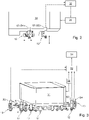
- feeder 01 In order to determine deviations in the position and/or dimensions of the sheets 06 to be fed into the processing machine by feeder 01 from a target position or a target dimension, feeder 01 now includes a sensor system whose Output signals by means of evaluation means 32, which are only indicated schematically here; 32', in particular correspondingly configured data processing means 32; 32', can be evaluated or are evaluated for any deviations in position and/or dimensions (see e.g. 2 and 3 or 8 ).
- the evaluation result can be displayed via an output interface, for example on a display means 34; 34' can be visualized.
- the above position is the position in a spanned by the sheet width and length, and given for the stack arrangement normal case of a level stand z. B. horizontal plane.
- the evaluation means 32; 32' control means 33; 33' e.g. B. data processing means 33; 33' with a control logic implemented in these, by means of which, depending on the evaluation result, a correction directed counter to the deviation can be brought about or is brought about, e.g. B. via a change in the position and / or location of handling tools 12; 13, in particular of the handling tools 12; 13 comprehensive sheet separator 14, for example by controlling one or more corresponding drive means via an associated drive control.
- this takes place automatically via the assigned control means 33; 33'.
- any sensor device can be provided, based on the output signal of which criteria characterizing the position and/or dimensions of the sheets 06 can be obtained and on the basis of which deviations in the position and/or dimensions of the sheets to be fed into the processing machine by feeder 01 06 can be determined for a target or target range and ideally quantified.
- At least one downstream and/or at least one upstream sensor S5, S6; S7; S8 can be the sensors for at least part of the Sheet 06 receiving handling tools 12; 13, in particular the sucker 12; 13 associated therewith as pressure sensors S1; S2; S3; S4 trained sensors S1; S2; S3; S4, through which a pressure P(S1); P(S2) or pressure curve in the suction cup 12; 13 or at a point of the sucker 12; 13 associated line path can be determined.
- a print P(S1); P(S2) or, in particular, the pressure profile, a criterion for the position and/or dimensions of sheets 06 is obtained.
- This determinable pressure P(S1); P(S2) represents, during active operation, for suckers 12 connected to a vacuum source; 13 shows a pressure curve with a negative pressure, ie a curve with a pressure P(S1) lying below ambient; P(S2), in the case of suckers operating according to the Bernoulli principle 12; 13 shows a pressure profile with an overpressure, ie a profile with a pressure P(S1) above ambient; P(S2).
- a load curve could also be used with the use of suckers 12; 13 by corresponding sensors S1; S2; S3; S4 in a different way, for example by mechanical force transducers or the like.
- two separating suckers 12 spaced transversely to the transport direction T are each provided with a sensor S1; S2, in particular pressure sensor S1; Assigned to S2, in particular integrated into it, by means of which a load or pressure curve can be determined when sheets 06 are lifted.
- two transport suckers 13 spaced transversely to the transport direction T are each provided with a sensor S3; S4, in particular pressure sensor S3; Assigned to S4, in particular integrated into it, through which a load profile, in particular pressure profile, can be determined during the transport of sheets 06 along the transport direction T.
- the lifting tools 12 and the transport tools 13 is preferably two transversely spaced handling tools 12; 13, a sensor S1; S2; S3; S4 assigned, both of which are within a width of a smallest sheet format to be fed and/or which are furthest apart in the smallest sheet format to be fed.
- a sensor S1; S2; S3; S4 assigned, both of which are within a width of a smallest sheet format to be fed and/or which are furthest apart in the smallest sheet format to be fed.
- these are the respective outermost handling tools 12; 13, but arranged in such a way that they also cover the narrowest format.
- the load or pressure profile on the individual handling tools 12; 13, in particular on two handling tools 12; 13 of the same type and/or in correlation with each other can basically be evaluated in any way and evaluated against a target.
- a feature A(S1) that is characteristic of the level and/or course; A(S2); A(S1, S2) are extracted or formed, this as a target with a result for the feature A(S1) currently obtained during recording and transport; A(S2); A(S1, S2) are compared and the result of the comparison is evaluated for deviations.
- the desired state can be determined by measuring a large number of sheets 06 that have been picked up and conveyed using statistical methods, e.g. B. as mean value M1; M2 with a confidence interval ⁇ that is or can be tolerated as a deviation, for example; ⁇ (S1); ⁇ (S2) is determined. It can be advantageous if this specific mean value M1; M2 is not static for further production, but can be defined via a large number of e.g. B. more than 50 most recently viewed events for feature A(S1); A(S2); A(S1, S2) as target with a confidence interval ⁇ ; y(S1); y(S2) is determined.
- statistical methods e.g. B. as mean value M1; M2 with a confidence interval ⁇ that is or can be tolerated as a deviation, for example; ⁇ (S1); ⁇ (S2) is determined.
- this specific mean value M1; M2 is not static for further production, but can be defined via a large number of e.
- the feature A(S1); A(S2); A(S1, S2) is a measure of the pressure P(S1); P(S2) over the full or at least part of a pick-up and delivery cycle of the suction cups 12 in question; 13 for picking up and conveying a sheet 06, ie a movement cycle until the starting position is assumed, under the curve, ie between the curve and the abscissa, resulting in surface areas A(S1); A(S2) to apply.
- a surface is above the abscissa in the case of overpressure and below it in the case of underpressure. This is e.g.
- Am 4 as an example and schematically based on the vacuum applied over a movement cycle of the left and right lifting suction device 12 and the surfaces lying between the respective curve and the axis relating to the tool phase position ⁇ .
- suction devices operated with excess pressure 12; 13 the same applies with the difference that the areas in the positive range for the pressure P(S1); P(S2) lie.
- the areas A(S1); A(S2) by integral formation, mathematical approximation methods such as e.g. B. be determined by a numerical integration or the application of a trapezoidal formula.
- the suction lifter 12 determined features A (S1); A(S2) or areas A(S1); A(S2) can be represented in a diagram as a cloud of points, for which, for example, a focus or center Z is calculated.
- mathematical-statistical methods for example the normal distribution according to Gauss, on the distribution of the values of the two areas A(S1); A(S2) combined feature A(S1, S2), z.
- B. construct a confidence ellipse within which a percentage of all points for the combined features A(S1, S2) corresponding to the confidence value ⁇ lie. As confidence values ⁇ z.
- the combined or linked consideration of the results for the characteristic feature A(S1); A(S2), here the areas A(S1); A(S2) multiple handling tools 12; 13 can be used to derive an error type, e.g. B. from early or late sheets, skewed sheets, double sheets or package layers.
- an error type e.g. B. from early or late sheets, skewed sheets, double sheets or package layers.
- results of a measurement on handling tools 13; 12 of the other type, for example on transport tools 13, are taken into account in a three-dimensional ellipsoid.
- Corresponding information about upcoming problems can then be sent via a broader database can be obtained.
- evaluation means 32 control means 33, z. B. data processing means 33 are assigned with an implemented control logic
- Deviations or automatically to the upcoming deviations In this case, the operator no longer has to intervene, or at least only in an emergency.
- Evaluation means 32 and control means 33 can be integrated in the same data processing unit or spatially separate and only connected in terms of signals.
- an inventive and/or particularly preferred embodiment of a feeder comprises a sensor system with at least one sensor S5, S6 on the side pointing in the transport direction T of the sheets 06 to be fed, i.e. on the front side of stack 09, and/or at least one sensor S7, S8 on the side facing away from transport direction T, i.e.
- the respective sensor S5; S6; S7; S8 is preferably arranged at a level below the top edge of the stack and/or at least arranged in such a way that it is directed to a point on the stack below the top edge of the stack and/or from the front or rear to the side of the stack in question.
- a sensor S5 designed as a laser scanner; S6, S7; S8 can be provided, which scans a distance or - in particular temporal - distance progression to the stack selectively at several points or continuously on at least one section of the stack width or at least provides information on the distance or distance progression and evaluates the determined distance or the relevant information.
- information about the alignment of the stack edge at the level of these points can be determined by evaluating at least two points that are spaced apart from one another and are at the same height.
- These sensors S5; S6 are spaced apart from one another transversely to the transport direction T and are preferably arranged at the same height and in the same horizontal alignment perpendicular to the transport direction T; S6 provided. They are preferably arranged in the area of front stops 16 .
- the sensors S5; S6 are preferably arranged at a level below the upper front edge of the stack and/or at least arranged in such a way that they are directed to a point on the stack below the upper front edge of the stack. They are arranged on both sides of an imaginary vertical center plane E, which bisects the stack 09 viewed in the transverse direction, but can, for example, correspond to the processed sheet format to be moved horizontally.
- S6 includes the sensors on the opposite side, i.e. the side facing away from the processing machine, i. H. Rear of the stack 09 two sensors S7; S8, in particular distance sensors S7; S8, through which a distance to a point on the back of the stack 09 can be measured - in particular at the same height.
- the sensors S7; S8 are also spaced apart from one another transversely to the transport direction T and are preferably provided at the same height and perpendicular to the transport direction T horizontally aligned.
- the sensors S7; S8 are preferably arranged at a level below the upper rear edge of the stack and/or at least arranged in such a way that they are directed to a point on the stack that is below the upper rear edge of the stack. They are arranged, for example, in columns 36 of a feeder frame, so that accessibility for changing piles is not impeded.
- the measured values at the two, preferably four, sensors S5; S6; S7; S8 collected and evaluated.
- evaluation means 32' are set up as data processing means 32', which occurs during the tracking, ie during the time to obtain the position of the top of the stack when the uppermost sheet 06 is removed, resulting in the profile of the at least two, preferably four, sensors S5; S6; S7; S8 to record the distances determined and to relate and evaluate their courses to one another.
- Results of the evaluation can be output, for example, to a display means 34' and/or a control means 33', in particular with appropriately programmed data processing means 33'.
- distances in particular a course of distances between sensors S5; S6; S7; S8 and stack 09 criteria that characterize the position and/or dimensions of the sheets 06 are derived.
- Mathematical statistical methods are preferably used in the evaluation.
- the measured values of the at least two, in particular four, sensors S5; S6; S7; S8 a profile of the stack 09 - on z. B. at least by sensors S5; S6; S7; S8 scanned page - which provides information about the length and/or the position, possibly down to individual sheets 06. Deviations in the length and/or in the position of the sheets 06 can be evaluated statistically.
- control means 33' are provided, by means of which such a deviation in the dimensions, here a length deviation of sheet 06, is detected from the measured values and such a deviation via a change in the position and/or location of handling tools 12; 13, in particular of the handling tools 12; 13 comprehensive sheet separator 14, for example by controlling one or more corresponding drive means, automated in training, is counteracted in order to prevent an error in the separation.
- the combined or linked consideration of the results for the characteristic criterion, here the - in particular temporal - distance profile at several points of the stack 09 can be used to derive a type of error, e.g. B. from early or late sheets, skewed sheets, double sheets or package layers
- the sensor system comprising the pressure sensors and/or the distance sensors with associated evaluation means 32; 32' are preferably the above control means 33; 33' is provided, which has a signal connection to the evaluation means 32; 32' and the first and/or second handling means 12; 13 directly or indirectly acting drive means to this depending on the result of to position the evaluation.
- an indirect drive can take place in that the handling tools 12; 13 comprehensive sheet separator 14 is provided or positioned.
Landscapes
- Engineering & Computer Science (AREA)
- Mechanical Engineering (AREA)
- Sheets, Magazines, And Separation Thereof (AREA)
- Controlling Sheets Or Webs (AREA)
- Registering Or Overturning Sheets (AREA)
Claims (14)
- Dispositif d'alimentation en feuilles (01) d'une machine de travail ou de traitement de feuilles, dans lequel une pile (09) de feuilles (06) à traiter peut être reçue, avec au moins deux premiers outils de maniement (12) espacés les uns des autres transversalement à une direction de transport (T) des feuilles (06), par lequel une feuille (06) au sommet d'une pile (09) reçue dans le dispositif d'alimentation en feuilles (01) peut être soulevée de la pile (09) et/ou avec au moins deux seconds outils de maniement (13) espacés les uns des autres transversalement à une direction de transport (T) des feuilles (06), par lequel une feuille (06) soulevée du sommet de la pile (09) peut être transportée en s'éloignant de la pile (09) dans la direction de transport (T) dans un chemin de transport raccordé en aval, caractérisé en ce qu'une technique sensorielle (S5, S6, S7, S8) est prévue, laquelle comprend un ou plusieurs capteurs (S5, S6) sur le côté avant de la pile (09) pointant dans la direction de transport (T) des feuilles (06) à amener, par lequel ou lesquels une information peut être établie quant à une distance pour au moins deux emplacements espacés les uns des autres transversalement à la direction de transport (T) sur le côté avant de la pile (09), et/ou en ce que la technique sensorielle (S5, S6, S7, S8) comprend un ou plusieurs capteurs (S5, S6) sur le côté arrière de la pile (09) orienté à l'encontre de la direction de transport (T), par lequel ou lesquels une information peut être établie quant à une distance pour au moins deux emplacements espacés les uns des autres transversalement à la direction de transport (T) sur le côté arrière de la pile (09).
- Dispositif d'alimentation en feuilles (01) selon la revendication 1, caractérisé en ce que la technique sensorielle (S5, S6, S7, S8) comprend deux capteurs (S5 ; S6) espacés l'un de l'autre transversalement à la direction de transport (T) et conçus en tant que capteurs de distance (S5 ; S6) sur le côté avant de la pile (09) pointant dans la direction de transport (T) des feuilles (06) à amener, par lesquels respectivement une distance ou un parcours de distance peut être établi pour respectivement un de deux emplacements espacés l'un de l'autre transversalement à la direction de transport (T) sur les côtés en aval de la pile (09), et/ou en ce qu'elle comprend deux capteurs (S7 ; S8) espacés l'un de l'autre transversalement à la direction de transport (T) et conçus en tant que capteurs de distance (S7 ; S8) sur le côté arrière de la pile (09) orienté à l'encontre de la direction de transport (T), par lesquels respectivement une distance ou un parcours de distance peut être établi pour respectivement un de deux emplacements espacés l'un de l'autre transversalement à la direction de transport (T) sur le côté arrière de la pile (09).
- Dispositif d'alimentation en feuilles (01) selon la revendication 1, caractérisé en ce que la technique sensorielle (S5, S6, S7, S8) comprend un capteur (S5 ; S7) conçu en tant que scanner laser sur le côté avant de la pile pointant dans la direction de transport (T) des feuilles (06) à amener et/ou sur le côté arrière de la pile (09) pointant à l'encontre de la direction de transport (T) des feuilles (06) à amener, par lequel des informations peuvent être établies, pour au moins deux emplacements espacés les uns des autres transversalement à la direction de transport (T), quant à une distance ou un parcours de distance sur la section entre les deux emplacements.
- Dispositif d'alimentation en feuilles (01) selon la revendication 1, 2 ou 3, caractérisé en ce qu'avec la technique sensorielle (S1, S2, S3, S4 ; S5, S6, S7, S8) sont prévus des moyens d'évaluation (32, 32') en liaison de signalisation, par lesquels des feuilles (06) à amener peuvent être surveillées sur des critères obtenus à partir des distances ou des informations et caractérisant la situation et/ou la dimension des feuilles (06), évaluées quant à un écart par rapport à une consigne ou une plage de consignes et des résultats de l'évaluation peuvent être donnés via une liaison de signalisation pour la visualisation à un moyen d'affichage (34 ; 34') et/ou pour la correction à un moyen de commande (33 ; 33').
- Dispositif d'alimentation en feuilles selon la revendication 1, 2, 3 ou 4, caractérisé en ce que les capteurs (S5, S6, S7, S8) sont agencés sur une hauteur se situant en-dessous du bord de pile supérieur et/ou au moins agencés de sorte qu'ils soient orientés sur un emplacement de la pile (09) se situant en-dessous du bord de pile supérieur.
- Dispositif d'alimentation en feuilles selon la revendication 1, 2, 3, 4 ou 5, caractérisé en ce que les moyens d'évaluation (32') sont aménagés en tant que moyens de traitement de données (32') pour enregistrer le parcours des distances établies par les capteurs de distance (S5 ; S6 ; S7 ; S8) se produisant pendant le suivi de la pile (09) et de fixer et évaluer leurs parcours en lien entre eux.
- Dispositif d'alimentation en feuilles selon la revendication 1, 2, 3, 4, 5 ou 6, caractérisé en ce que les moyens de commande (33, 33') en liaison de signalisation avec les moyens d'évaluation (32, 32') sont en liaison de signalisation avec des moyens d'entraînement réglant indirectement ou directement les premiers et/ou seconds outils de maniement (12 ; 13) pour positionner ceux-ci en fonction du résultat de l'évaluation.
- Dispositif d'alimentation en feuilles selon la revendication 1, 2, 3, 4, 5, 6 ou 7, caractérisé en ce que les deux premiers et/ou seconds outils de maniement (12 ; 13) sont configurés en tant qu'aspirateurs (12 ; 13), et en ce que la technique sensorielle (S1, S2, S3, S4 ; S5, S6, S7, S8) comprend des capteurs (S1, S2, S3, S4) conçus en tant que capteurs de pression (S1, S2, S3, S4) et respectivement attribués aux premiers et/ou seconds outils de maniement (12; 13), par lesquels en tant que critère caractérisant une situation et/ou une dimension de feuilles (06) peut être établi un parcours de pression dans l'outil de maniement (12 ; 13) concerné ou en un emplacement du chemin conducteur attribué à l'outil de maniement (12 ; 13), et en ce que des moyens d'évaluation (32) sont aménagés en tant que moyens de traitement de données (32) afin d'extraire ou de former une caractéristique caractérisante (A(S1) ; A(S2)) pour le parcours à partir du parcours de pression établi en utilisant des méthodes mathématiques et de la donner en tant que résultat au moyen d'affichage et/ou au moyen de commande (33).
- Dispositif d'alimentation en feuilles selon la revendication 8, caractérisé en ce que les moyens d'évaluation (32) sont aménagés en tant que moyens de traitement de données (32') afin d'extraire ou de former une caractéristique caractérisante (A(S1) ; A(S2)) pour le parcours à partir du parcours de pression établi en utilisant des méthodes mathématiques et de la donner en tant que résultat au moyen d'affichage et/ou au moyen de commande (33).
- Procédé de saisie et/ou de correction de feuilles (06) s'écartant en termes de situation et/ou de dimensions dans un dispositif d'alimentation en feuilles d'une machine de travail ou de traitement de feuilles (06), en particulier en utilisant un dispositif selon l'une des revendications 1 à 6, dans lequel successivement les feuilles (06) se situant respectivement au-dessus d'une pile (09) peuvent être soulevées au moyen d'au moins deux premiers outils de maniement (12) espacés les uns des autres transversalement à une direction de transport (T) des feuilles (06) et/ou sont transportés au moyen de deux seconds outils de maniement (13) espacés les uns des autres transversalement à une direction de transport (T) des feuilles (06) en s'éloignant de la pile (09) dans la direction de transport (T) dans un chemin de transport raccordé en aval, caractérisé en ce qu'au moyen d'une technique sensorielle (S1, S2, S3, S4 ; S5, S6, S7, S8), des feuilles (06) à amener à la machine de travail ou de traitement de feuilles sont surveillées et évaluées quant à une situation et/ou une dimension des feuilles (06), et des résultats de l'évaluation sont visualisés et ou utilisés pour une correction automatisée, caractérisé en ce que par la technique sensorielle (S5, S6, S7, S8) une distance ou un parcours de distance ou au moins une information quant à une distance ou un parcours de distance pour deux emplacements espacés l'un de l'autre transversalement à la direction de transport (T) sur le côté avant de la pile (09) pointant dans la direction de transport (T) des feuilles (06) à amener est établi(e) au moyen d'un ou deux capteurs (S5 ; S6) espacés l'un de l'autre transversalement à la direction de transport (T), et/ou une distance ou un parcours de distance ou au moins une information quant à une distance ou un parcours de distance pour deux emplacements espacés l'un de l'autre transversalement à la direction de transport (T) sur le côté arrière de la pile (09) orienté à l'encontre de la direction de transport (T) est établi(e) au moyen d'un ou deux capteurs (S7 ; S8) espacés l'un de l'autre transversalement à la direction de transport (T).
- Procédé selon la revendication 10, caractérisé en ce qu'une distance ou un parcours de distance est établi pour respectivement un de deux emplacements espacés l'un de l'autre transversalement à la direction de transport (T) sur le côté en aval de la pile (09) au moyen de deux capteurs (S5 ; S6) espacés l'un de l'autre transversalement à la direction de transport (T) et conçus en tant que capteurs de distance (S5 ; S6) sur le côté avant de la pile (09) pointant dans la direction de transport (T) des feuilles (06) à amener, et/ou respectivement une distance ou un parcours de distance est mesuré pour respectivement un de deux emplacements espacés l'un de l'autre transversalement à la direction de transport (T) sur le côté arrière de la pile (09) au moyen de deux capteurs (S7 ; S8) espacés l'un de l'autre transversalement à la direction de transport (T) et conçus en tant que capteurs de distance (S7 ; S8) sur le côté arrière de la pile (09) opposé au chemin de transport .
- Procédé selon la revendication 10 ou 11, caractérisé en ce que des résultats obtenus via plusieurs capteurs (S5 ; S6 ; S7 ; S8) sont associés et utilisés pour dériver et/ou corriger un type d'erreur.
- Procédé selon la revendication 10, 11 ou 12, caractérisé en ce que, par les capteurs de distance (S5 ; S6 ; S7 S8) côtés avant et arrière sur le côté avant et arrière de la pile (09), est fourni, à respectivement deux emplacements espacés l'un de l'autre transversalement à la direction de transport (T), un profil pour la délimitation de pile latérale de la partie de la pile (09) qui se situe au-dessus des emplacements concernés et a déjà continué à être acheminée à la verticale via ces emplacements.
- Procédé selon la revendication 10, 11, 12 ou 13, caractérisé en ce que, pour la correction d'une erreur de positionnement ou d'un écart non souhaité(e), une modification dans la position d'un ou plusieurs des outils de maniement (12 ; 13) ou d'un séparateur de feuilles (14) comprenant les outils de maniement (12 ; 13) se produit par pilotage d'un ou plusieurs moyens d'entraînement prévus pour le positionnement.
Applications Claiming Priority (2)
| Application Number | Priority Date | Filing Date | Title |
|---|---|---|---|
| DE102020124432.0A DE102020124432B4 (de) | 2020-09-18 | 2020-09-18 | Anleger einer Bogen be- oder verarbeitende Maschine sowie Verfahren zur Erfassung und/oder Korrektur von in Lage und/oder Abmessungen abweichenden Bogen in einem Anleger einer Bogen be- oder verarbeitende Maschine |
| PCT/EP2021/063611 WO2022058058A1 (fr) | 2020-09-18 | 2021-05-21 | Dispositif d'alimentation d'une machine de traitement de feuilles et procédé de détection et/ou de correction de feuilles divergentes en position et/ou en dimensions dans un dispositif d'alimentation d'une machine de traitement de feuilles |
Publications (2)
| Publication Number | Publication Date |
|---|---|
| EP4021834A1 EP4021834A1 (fr) | 2022-07-06 |
| EP4021834B1 true EP4021834B1 (fr) | 2022-10-19 |
Family
ID=76217819
Family Applications (1)
| Application Number | Title | Priority Date | Filing Date |
|---|---|---|---|
| EP21729234.1A Active EP4021834B1 (fr) | 2020-09-18 | 2021-05-21 | Dispositif d'alimentation d'une machine de traitement de feuilles et procédé de détection et/ou de correction de feuilles divergentes en position et/ou en dimensions dans un dispositif d'alimentation d'une machine de traitement de feuilles |
Country Status (6)
| Country | Link |
|---|---|
| US (1) | US11685621B2 (fr) |
| EP (1) | EP4021834B1 (fr) |
| JP (1) | JP7447157B2 (fr) |
| CN (1) | CN114555494B (fr) |
| DE (1) | DE102020124432B4 (fr) |
| WO (1) | WO2022058058A1 (fr) |
Families Citing this family (4)
| Publication number | Priority date | Publication date | Assignee | Title |
|---|---|---|---|---|
| EP4223678A1 (fr) * | 2022-02-04 | 2023-08-09 | Weber Maschinenbau GmbH Breidenbach | Appareil de distribution de carton |
| DE102023103827B3 (de) * | 2023-02-16 | 2023-12-21 | Heidelberger Druckmaschinen Aktiengesellschaft | Verfahren zur Steuerung eines Bogenanlegers |
| DE102023104999A1 (de) * | 2023-03-01 | 2024-09-05 | Koenig & Bauer Ag | Anleger einer bogenverarbeitenden Maschine und Verfahren zum Betreiben eines Anlegers einer bogenverarbeitenden Maschine |
| DE102024128387A1 (de) * | 2024-10-01 | 2026-04-02 | Powerco Se | Vorrichtung und Verfahren zur Entnahme von Elektrodenblättern aus einem Magazin |
Family Cites Families (15)
| Publication number | Priority date | Publication date | Assignee | Title |
|---|---|---|---|---|
| JPS5661248A (en) * | 1979-10-17 | 1981-05-26 | Toppan Printing Co Ltd | Paper feed abnormality sensor for printer |
| JPS60119045U (ja) * | 1984-01-19 | 1985-08-12 | 凸版印刷株式会社 | 薄板の自動搬送装置 |
| JPS6160533A (ja) * | 1984-08-31 | 1986-03-28 | Fuji Xerox Co Ltd | 複写機の用紙検出装置 |
| DE3907037C2 (de) | 1989-03-04 | 1994-03-24 | Heidelberger Druckmasch Ag | Vorrichtung zur Bogenlängenabfrage in einer Bogen bearbeitenden Maschine |
| US5803447A (en) * | 1996-09-25 | 1998-09-08 | D&K Custom Machine Design, Inc. | Method and apparatus for feeding sheets |
| DE19917405B4 (de) * | 1999-04-16 | 2005-04-14 | LTG Mailänder GmbH & Co. KG | Verfahren und Vorrichtung zum Vereinzeln flexibler flächiger Gegenstände |
| DE10100191C2 (de) | 2001-01-04 | 2003-10-09 | Koenig & Bauer Ag | Bogenanleger |
| DE10151484B4 (de) | 2001-10-18 | 2005-07-28 | Man Roland Druckmaschinen Ag | Bogenanleger |
| DE102004005575A1 (de) | 2003-03-03 | 2004-09-16 | Heidelberger Druckmaschinen Ag | Verfahren und Vorrichtung zum Steuern der Bogenzufuhr zu einer drucktechnischen Maschine |
| DE10356107B4 (de) | 2003-11-27 | 2021-05-27 | Mabeg Systems Gmbh | Bogenanleger mit Vorderkantentrennung und berührungsloser Stapelabtastung |
| US7411205B2 (en) * | 2005-03-04 | 2008-08-12 | Xerox Corporation | In-stack sheet thickness measuring system |
| SE530098C2 (sv) | 2006-07-19 | 2008-03-04 | Xerex Ab | Sätt och anordning varmed alstras och tilll ett ark i en arkmatad tryckpress fördelas ett från atmosfärtryck skilt lufttryck för att verkställa eller påverka arkets transport i tryckpressen |
| DE102015204558B4 (de) | 2015-03-13 | 2018-04-05 | Koenig & Bauer Ag | Vorrichtung zum Ausrichten von Bogen |
| JP2018065647A (ja) * | 2016-10-19 | 2018-04-26 | 三菱製紙株式会社 | 枚葉印刷機の給紙部 |
| JP2019059582A (ja) * | 2017-09-26 | 2019-04-18 | 三菱製紙株式会社 | 枚葉印刷機の給紙部 |
-
2020
- 2020-09-18 DE DE102020124432.0A patent/DE102020124432B4/de not_active Expired - Fee Related
-
2021
- 2021-05-21 CN CN202180004042.0A patent/CN114555494B/zh active Active
- 2021-05-21 JP JP2021576371A patent/JP7447157B2/ja active Active
- 2021-05-21 US US17/621,311 patent/US11685621B2/en active Active
- 2021-05-21 EP EP21729234.1A patent/EP4021834B1/fr active Active
- 2021-05-21 WO PCT/EP2021/063611 patent/WO2022058058A1/fr not_active Ceased
Also Published As
| Publication number | Publication date |
|---|---|
| CN114555494A (zh) | 2022-05-27 |
| WO2022058058A1 (fr) | 2022-03-24 |
| US11685621B2 (en) | 2023-06-27 |
| JP7447157B2 (ja) | 2024-03-11 |
| DE102020124432A1 (de) | 2022-03-24 |
| EP4021834A1 (fr) | 2022-07-06 |
| JP2023513986A (ja) | 2023-04-05 |
| CN114555494B (zh) | 2024-01-09 |
| US20220348430A1 (en) | 2022-11-03 |
| DE102020124432B4 (de) | 2022-07-07 |
Similar Documents
| Publication | Publication Date | Title |
|---|---|---|
| EP4021834B1 (fr) | Dispositif d'alimentation d'une machine de traitement de feuilles et procédé de détection et/ou de correction de feuilles divergentes en position et/ou en dimensions dans un dispositif d'alimentation d'une machine de traitement de feuilles | |
| DE102009034443A1 (de) | Verfahren und Vorrichtung zum Zuführen von Bogen zu einer Verarbeitungsmaschine | |
| EP3224169B1 (fr) | Machine de traitement de feuilles munie d'une sortie et procédé de dépôt de feuilles | |
| DE102010027119A1 (de) | Verfahren und Vorrichtung zum Positionieren von Bogen | |
| DE102020124433B4 (de) | Anleger einer Bogen be- oder verarbeitende Maschine sowie Verfahren zur Unterstützung der Bogenvereinzelung in einem Anleger einer Bogen be- oder verarbeitende Maschine | |
| DE102015203412B4 (de) | Stapelanhebevorrichtung | |
| WO2017190258A1 (fr) | Procédé et dispositif permettant d'amener une feuille de tôle à une presse de découpage | |
| DE102016212712B4 (de) | Bogenanleger | |
| DE10105991A1 (de) | Verfahren zur Steuerung der Bogenzufuhr zu einer drucktechnischen Maschine | |
| DE102023104999A1 (de) | Anleger einer bogenverarbeitenden Maschine und Verfahren zum Betreiben eines Anlegers einer bogenverarbeitenden Maschine | |
| DE10033490B4 (de) | Einrichtung zum seitlichen Ausrichten von Bogen | |
| DE102022101198B4 (de) | Bogenanleger und Verfahren zum Betreiben eines Bogenanlegers | |
| EP2918530B1 (fr) | Dispositif destiné au positionnement d'un bord avant de feuille | |
| DE102023135280B3 (de) | Verfahren zum Betreiben einer bogenverarbeitenden Maschine | |
| DE102006025074A1 (de) | Verfahren und Vorrichtung zum Transport von Bogen zu einer bogenverarbeitenden Maschine | |
| EP1582490A1 (fr) | Dispositif d'alimentation d'un courant de feuilles se chevauchant | |
| DE102015209905A1 (de) | Kontrolleinrichtung zum Überwachen eines Grenzwerts einer Schichtdicke und/oder einer Anzahl von mehreren zumindest teilweise aufeinander liegenden Materialabschnitten in einem Fühlspalt | |
| DE102017208165B4 (de) | Bogenverarbeitende Maschine mit Bogenführungszylindern und einer Auslage und Verfahren zum Betreiben einer bogenverarbeitenden Maschine | |
| DE102021115423A1 (de) | Anleger einer Bogenbearbeitungsmaschine und Verfahren zum Bogentrennen | |
| EP1593625A1 (fr) | Margeur du bord avant | |
| DE102020107837A1 (de) | Bogenverarbeitende Maschine mit einem Bogentrenner | |
| DE102015204558B4 (de) | Vorrichtung zum Ausrichten von Bogen | |
| DE102022100523B4 (de) | Bogenverarbeitende Maschine mit einem Anleger und Verfahren zum Betreiben einer bogenverarbeitenden Maschine | |
| EP4168338B1 (fr) | Unité d'introduction d'une machine à travailler les feuilles ou de traitement de feuilles dotée d'un dispositif de projection | |
| EP4086209B1 (fr) | Dispositif et procédé de séparation de marchandises plates et d'alimentation d'une unité d'usinage |
Legal Events
| Date | Code | Title | Description |
|---|---|---|---|
| STAA | Information on the status of an ep patent application or granted ep patent |
Free format text: STATUS: UNKNOWN |
|
| STAA | Information on the status of an ep patent application or granted ep patent |
Free format text: STATUS: THE INTERNATIONAL PUBLICATION HAS BEEN MADE |
|
| PUAI | Public reference made under article 153(3) epc to a published international application that has entered the european phase |
Free format text: ORIGINAL CODE: 0009012 |
|
| STAA | Information on the status of an ep patent application or granted ep patent |
Free format text: STATUS: REQUEST FOR EXAMINATION WAS MADE |
|
| 17P | Request for examination filed |
Effective date: 20211201 |
|
| AK | Designated contracting states |
Kind code of ref document: A1 Designated state(s): AL AT BE BG CH CY CZ DE DK EE ES FI FR GB GR HR HU IE IS IT LI LT LU LV MC MK MT NL NO PL PT RO RS SE SI SK SM TR |
|
| GRAP | Despatch of communication of intention to grant a patent |
Free format text: ORIGINAL CODE: EPIDOSNIGR1 |
|
| STAA | Information on the status of an ep patent application or granted ep patent |
Free format text: STATUS: GRANT OF PATENT IS INTENDED |
|
| INTG | Intention to grant announced |
Effective date: 20220715 |
|
| GRAS | Grant fee paid |
Free format text: ORIGINAL CODE: EPIDOSNIGR3 |
|
| GRAA | (expected) grant |
Free format text: ORIGINAL CODE: 0009210 |
|
| STAA | Information on the status of an ep patent application or granted ep patent |
Free format text: STATUS: THE PATENT HAS BEEN GRANTED |
|
| DAV | Request for validation of the european patent (deleted) | ||
| DAX | Request for extension of the european patent (deleted) | ||
| AK | Designated contracting states |
Kind code of ref document: B1 Designated state(s): AL AT BE BG CH CY CZ DE DK EE ES FI FR GB GR HR HU IE IS IT LI LT LU LV MC MK MT NL NO PL PT RO RS SE SI SK SM TR |
|
| REG | Reference to a national code |
Ref country code: GB Ref legal event code: FG4D Free format text: NOT ENGLISH |
|
| REG | Reference to a national code |
Ref country code: CH Ref legal event code: EP |
|
| REG | Reference to a national code |
Ref country code: IE Ref legal event code: FG4D Free format text: LANGUAGE OF EP DOCUMENT: GERMAN |
|
| REG | Reference to a national code |
Ref country code: DE Ref legal event code: R096 Ref document number: 502021000205 Country of ref document: DE |
|
| REG | Reference to a national code |
Ref country code: AT Ref legal event code: REF Ref document number: 1525434 Country of ref document: AT Kind code of ref document: T Effective date: 20221115 |
|
| REG | Reference to a national code |
Ref country code: LT Ref legal event code: MG9D |
|
| REG | Reference to a national code |
Ref country code: NL Ref legal event code: MP Effective date: 20221019 |
|
| PG25 | Lapsed in a contracting state [announced via postgrant information from national office to epo] |
Ref country code: NL Free format text: LAPSE BECAUSE OF FAILURE TO SUBMIT A TRANSLATION OF THE DESCRIPTION OR TO PAY THE FEE WITHIN THE PRESCRIBED TIME-LIMIT Effective date: 20221019 |
|
| PG25 | Lapsed in a contracting state [announced via postgrant information from national office to epo] |
Ref country code: SE Free format text: LAPSE BECAUSE OF FAILURE TO SUBMIT A TRANSLATION OF THE DESCRIPTION OR TO PAY THE FEE WITHIN THE PRESCRIBED TIME-LIMIT Effective date: 20221019 Ref country code: PT Free format text: LAPSE BECAUSE OF FAILURE TO SUBMIT A TRANSLATION OF THE DESCRIPTION OR TO PAY THE FEE WITHIN THE PRESCRIBED TIME-LIMIT Effective date: 20230220 Ref country code: NO Free format text: LAPSE BECAUSE OF FAILURE TO SUBMIT A TRANSLATION OF THE DESCRIPTION OR TO PAY THE FEE WITHIN THE PRESCRIBED TIME-LIMIT Effective date: 20230119 Ref country code: LT Free format text: LAPSE BECAUSE OF FAILURE TO SUBMIT A TRANSLATION OF THE DESCRIPTION OR TO PAY THE FEE WITHIN THE PRESCRIBED TIME-LIMIT Effective date: 20221019 Ref country code: FI Free format text: LAPSE BECAUSE OF FAILURE TO SUBMIT A TRANSLATION OF THE DESCRIPTION OR TO PAY THE FEE WITHIN THE PRESCRIBED TIME-LIMIT Effective date: 20221019 Ref country code: ES Free format text: LAPSE BECAUSE OF FAILURE TO SUBMIT A TRANSLATION OF THE DESCRIPTION OR TO PAY THE FEE WITHIN THE PRESCRIBED TIME-LIMIT Effective date: 20221019 |
|
| PG25 | Lapsed in a contracting state [announced via postgrant information from national office to epo] |
Ref country code: RS Free format text: LAPSE BECAUSE OF FAILURE TO SUBMIT A TRANSLATION OF THE DESCRIPTION OR TO PAY THE FEE WITHIN THE PRESCRIBED TIME-LIMIT Effective date: 20221019 Ref country code: PL Free format text: LAPSE BECAUSE OF FAILURE TO SUBMIT A TRANSLATION OF THE DESCRIPTION OR TO PAY THE FEE WITHIN THE PRESCRIBED TIME-LIMIT Effective date: 20221019 Ref country code: LV Free format text: LAPSE BECAUSE OF FAILURE TO SUBMIT A TRANSLATION OF THE DESCRIPTION OR TO PAY THE FEE WITHIN THE PRESCRIBED TIME-LIMIT Effective date: 20221019 Ref country code: IS Free format text: LAPSE BECAUSE OF FAILURE TO SUBMIT A TRANSLATION OF THE DESCRIPTION OR TO PAY THE FEE WITHIN THE PRESCRIBED TIME-LIMIT Effective date: 20230219 Ref country code: HR Free format text: LAPSE BECAUSE OF FAILURE TO SUBMIT A TRANSLATION OF THE DESCRIPTION OR TO PAY THE FEE WITHIN THE PRESCRIBED TIME-LIMIT Effective date: 20221019 Ref country code: GR Free format text: LAPSE BECAUSE OF FAILURE TO SUBMIT A TRANSLATION OF THE DESCRIPTION OR TO PAY THE FEE WITHIN THE PRESCRIBED TIME-LIMIT Effective date: 20230120 |
|
| REG | Reference to a national code |
Ref country code: DE Ref legal event code: R097 Ref document number: 502021000205 Country of ref document: DE |
|
| PG25 | Lapsed in a contracting state [announced via postgrant information from national office to epo] |
Ref country code: SM Free format text: LAPSE BECAUSE OF FAILURE TO SUBMIT A TRANSLATION OF THE DESCRIPTION OR TO PAY THE FEE WITHIN THE PRESCRIBED TIME-LIMIT Effective date: 20221019 Ref country code: RO Free format text: LAPSE BECAUSE OF FAILURE TO SUBMIT A TRANSLATION OF THE DESCRIPTION OR TO PAY THE FEE WITHIN THE PRESCRIBED TIME-LIMIT Effective date: 20221019 Ref country code: EE Free format text: LAPSE BECAUSE OF FAILURE TO SUBMIT A TRANSLATION OF THE DESCRIPTION OR TO PAY THE FEE WITHIN THE PRESCRIBED TIME-LIMIT Effective date: 20221019 Ref country code: DK Free format text: LAPSE BECAUSE OF FAILURE TO SUBMIT A TRANSLATION OF THE DESCRIPTION OR TO PAY THE FEE WITHIN THE PRESCRIBED TIME-LIMIT Effective date: 20221019 Ref country code: CZ Free format text: LAPSE BECAUSE OF FAILURE TO SUBMIT A TRANSLATION OF THE DESCRIPTION OR TO PAY THE FEE WITHIN THE PRESCRIBED TIME-LIMIT Effective date: 20221019 |
|
| PLBE | No opposition filed within time limit |
Free format text: ORIGINAL CODE: 0009261 |
|
| STAA | Information on the status of an ep patent application or granted ep patent |
Free format text: STATUS: NO OPPOSITION FILED WITHIN TIME LIMIT |
|
| PG25 | Lapsed in a contracting state [announced via postgrant information from national office to epo] |
Ref country code: SK Free format text: LAPSE BECAUSE OF FAILURE TO SUBMIT A TRANSLATION OF THE DESCRIPTION OR TO PAY THE FEE WITHIN THE PRESCRIBED TIME-LIMIT Effective date: 20221019 Ref country code: AL Free format text: LAPSE BECAUSE OF FAILURE TO SUBMIT A TRANSLATION OF THE DESCRIPTION OR TO PAY THE FEE WITHIN THE PRESCRIBED TIME-LIMIT Effective date: 20221019 |
|
| 26N | No opposition filed |
Effective date: 20230720 |
|
| PG25 | Lapsed in a contracting state [announced via postgrant information from national office to epo] |
Ref country code: SI Free format text: LAPSE BECAUSE OF FAILURE TO SUBMIT A TRANSLATION OF THE DESCRIPTION OR TO PAY THE FEE WITHIN THE PRESCRIBED TIME-LIMIT Effective date: 20221019 |
|
| PG25 | Lapsed in a contracting state [announced via postgrant information from national office to epo] |
Ref country code: MC Free format text: LAPSE BECAUSE OF FAILURE TO SUBMIT A TRANSLATION OF THE DESCRIPTION OR TO PAY THE FEE WITHIN THE PRESCRIBED TIME-LIMIT Effective date: 20221019 |
|
| REG | Reference to a national code |
Ref country code: BE Ref legal event code: MM Effective date: 20230531 |
|
| PG25 | Lapsed in a contracting state [announced via postgrant information from national office to epo] |
Ref country code: MC Free format text: LAPSE BECAUSE OF FAILURE TO SUBMIT A TRANSLATION OF THE DESCRIPTION OR TO PAY THE FEE WITHIN THE PRESCRIBED TIME-LIMIT Effective date: 20221019 Ref country code: LU Free format text: LAPSE BECAUSE OF NON-PAYMENT OF DUE FEES Effective date: 20230521 |
|
| REG | Reference to a national code |
Ref country code: IE Ref legal event code: MM4A |
|
| PG25 | Lapsed in a contracting state [announced via postgrant information from national office to epo] |
Ref country code: IE Free format text: LAPSE BECAUSE OF NON-PAYMENT OF DUE FEES Effective date: 20230521 |
|
| PG25 | Lapsed in a contracting state [announced via postgrant information from national office to epo] |
Ref country code: IE Free format text: LAPSE BECAUSE OF NON-PAYMENT OF DUE FEES Effective date: 20230521 |
|
| PG25 | Lapsed in a contracting state [announced via postgrant information from national office to epo] |
Ref country code: IT Free format text: LAPSE BECAUSE OF FAILURE TO SUBMIT A TRANSLATION OF THE DESCRIPTION OR TO PAY THE FEE WITHIN THE PRESCRIBED TIME-LIMIT Effective date: 20221019 Ref country code: BE Free format text: LAPSE BECAUSE OF NON-PAYMENT OF DUE FEES Effective date: 20230531 |
|
| PGFP | Annual fee paid to national office [announced via postgrant information from national office to epo] |
Ref country code: FR Payment date: 20240522 Year of fee payment: 4 |
|
| PG25 | Lapsed in a contracting state [announced via postgrant information from national office to epo] |
Ref country code: BG Free format text: LAPSE BECAUSE OF FAILURE TO SUBMIT A TRANSLATION OF THE DESCRIPTION OR TO PAY THE FEE WITHIN THE PRESCRIBED TIME-LIMIT Effective date: 20221019 |
|
| PG25 | Lapsed in a contracting state [announced via postgrant information from national office to epo] |
Ref country code: BG Free format text: LAPSE BECAUSE OF FAILURE TO SUBMIT A TRANSLATION OF THE DESCRIPTION OR TO PAY THE FEE WITHIN THE PRESCRIBED TIME-LIMIT Effective date: 20221019 |
|
| PGFP | Annual fee paid to national office [announced via postgrant information from national office to epo] |
Ref country code: DE Payment date: 20250603 Year of fee payment: 5 |
|
| PGFP | Annual fee paid to national office [announced via postgrant information from national office to epo] |
Ref country code: CH Payment date: 20250601 Year of fee payment: 5 |
|
| PGFP | Annual fee paid to national office [announced via postgrant information from national office to epo] |
Ref country code: AT Payment date: 20250721 Year of fee payment: 5 |
|
| PG25 | Lapsed in a contracting state [announced via postgrant information from national office to epo] |
Ref country code: CY Free format text: LAPSE BECAUSE OF FAILURE TO SUBMIT A TRANSLATION OF THE DESCRIPTION OR TO PAY THE FEE WITHIN THE PRESCRIBED TIME-LIMIT; INVALID AB INITIO Effective date: 20210521 |
|
| PG25 | Lapsed in a contracting state [announced via postgrant information from national office to epo] |
Ref country code: HU Free format text: LAPSE BECAUSE OF FAILURE TO SUBMIT A TRANSLATION OF THE DESCRIPTION OR TO PAY THE FEE WITHIN THE PRESCRIBED TIME-LIMIT; INVALID AB INITIO Effective date: 20210521 |
|
| PG25 | Lapsed in a contracting state [announced via postgrant information from national office to epo] |
Ref country code: TR Free format text: LAPSE BECAUSE OF FAILURE TO SUBMIT A TRANSLATION OF THE DESCRIPTION OR TO PAY THE FEE WITHIN THE PRESCRIBED TIME-LIMIT Effective date: 20221019 |
|
| GBPC | Gb: european patent ceased through non-payment of renewal fee |
Effective date: 20250521 |
|
| PG25 | Lapsed in a contracting state [announced via postgrant information from national office to epo] |
Ref country code: GB Free format text: LAPSE BECAUSE OF NON-PAYMENT OF DUE FEES Effective date: 20250521 |
|
| PG25 | Lapsed in a contracting state [announced via postgrant information from national office to epo] |
Ref country code: FR Free format text: LAPSE BECAUSE OF NON-PAYMENT OF DUE FEES Effective date: 20250531 |