EP4022290B1 - Procédé et produit programme informatique pour la détection automatisée d'erreurs d'une boroscopie sur moteur - Google Patents
Procédé et produit programme informatique pour la détection automatisée d'erreurs d'une boroscopie sur moteur Download PDFInfo
- Publication number
- EP4022290B1 EP4022290B1 EP20761242.5A EP20761242A EP4022290B1 EP 4022290 B1 EP4022290 B1 EP 4022290B1 EP 20761242 A EP20761242 A EP 20761242A EP 4022290 B1 EP4022290 B1 EP 4022290B1
- Authority
- EP
- European Patent Office
- Prior art keywords
- engine
- movement
- video
- blades
- borescope
- Prior art date
- Legal status (The legal status is an assumption and is not a legal conclusion. Google has not performed a legal analysis and makes no representation as to the accuracy of the status listed.)
- Active
Links
Images


Classifications
-
- G—PHYSICS
- G01—MEASURING; TESTING
- G01N—INVESTIGATING OR ANALYSING MATERIALS BY DETERMINING THEIR CHEMICAL OR PHYSICAL PROPERTIES
- G01N21/00—Investigating or analysing materials by the use of optical means, i.e. using sub-millimetre waves, infrared, visible or ultraviolet light
- G01N21/84—Systems specially adapted for particular applications
- G01N21/88—Investigating the presence of flaws or contamination
- G01N21/95—Investigating the presence of flaws or contamination characterised by the material or shape of the object to be examined
- G01N21/954—Inspecting the inner surface of hollow bodies, e.g. bores
-
- G—PHYSICS
- G01—MEASURING; TESTING
- G01N—INVESTIGATING OR ANALYSING MATERIALS BY DETERMINING THEIR CHEMICAL OR PHYSICAL PROPERTIES
- G01N21/00—Investigating or analysing materials by the use of optical means, i.e. using sub-millimetre waves, infrared, visible or ultraviolet light
- G01N21/84—Systems specially adapted for particular applications
- G01N21/88—Investigating the presence of flaws or contamination
- G01N21/8851—Scan or image signal processing specially adapted therefor, e.g. for scan signal adjustment, for detecting different kinds of defects, for compensating for structures, markings, edges
-
- G—PHYSICS
- G01—MEASURING; TESTING
- G01N—INVESTIGATING OR ANALYSING MATERIALS BY DETERMINING THEIR CHEMICAL OR PHYSICAL PROPERTIES
- G01N21/00—Investigating or analysing materials by the use of optical means, i.e. using sub-millimetre waves, infrared, visible or ultraviolet light
- G01N21/84—Systems specially adapted for particular applications
- G01N21/88—Investigating the presence of flaws or contamination
- G01N21/89—Investigating the presence of flaws or contamination in moving material, e.g. running paper or textiles
- G01N21/892—Investigating the presence of flaws or contamination in moving material, e.g. running paper or textiles characterised by the flaw, defect or object feature examined
-
- G—PHYSICS
- G01—MEASURING; TESTING
- G01N—INVESTIGATING OR ANALYSING MATERIALS BY DETERMINING THEIR CHEMICAL OR PHYSICAL PROPERTIES
- G01N21/00—Investigating or analysing materials by the use of optical means, i.e. using sub-millimetre waves, infrared, visible or ultraviolet light
- G01N21/84—Systems specially adapted for particular applications
- G01N21/88—Investigating the presence of flaws or contamination
- G01N21/95—Investigating the presence of flaws or contamination characterised by the material or shape of the object to be examined
- G01N21/9515—Objects of complex shape, e.g. examined with use of a surface follower device
-
- G—PHYSICS
- G06—COMPUTING OR CALCULATING; COUNTING
- G06T—IMAGE DATA PROCESSING OR GENERATION, IN GENERAL
- G06T7/00—Image analysis
- G06T7/0002—Inspection of images, e.g. flaw detection
- G06T7/0004—Industrial image inspection
-
- G—PHYSICS
- G01—MEASURING; TESTING
- G01N—INVESTIGATING OR ANALYSING MATERIALS BY DETERMINING THEIR CHEMICAL OR PHYSICAL PROPERTIES
- G01N21/00—Investigating or analysing materials by the use of optical means, i.e. using sub-millimetre waves, infrared, visible or ultraviolet light
- G01N21/84—Systems specially adapted for particular applications
- G01N21/88—Investigating the presence of flaws or contamination
- G01N21/8851—Scan or image signal processing specially adapted therefor, e.g. for scan signal adjustment, for detecting different kinds of defects, for compensating for structures, markings, edges
- G01N2021/8883—Scan or image signal processing specially adapted therefor, e.g. for scan signal adjustment, for detecting different kinds of defects, for compensating for structures, markings, edges involving the calculation of gauges, generating models
-
- G—PHYSICS
- G01—MEASURING; TESTING
- G01N—INVESTIGATING OR ANALYSING MATERIALS BY DETERMINING THEIR CHEMICAL OR PHYSICAL PROPERTIES
- G01N21/00—Investigating or analysing materials by the use of optical means, i.e. using sub-millimetre waves, infrared, visible or ultraviolet light
- G01N21/84—Systems specially adapted for particular applications
- G01N21/88—Investigating the presence of flaws or contamination
- G01N21/8851—Scan or image signal processing specially adapted therefor, e.g. for scan signal adjustment, for detecting different kinds of defects, for compensating for structures, markings, edges
- G01N2021/8887—Scan or image signal processing specially adapted therefor, e.g. for scan signal adjustment, for detecting different kinds of defects, for compensating for structures, markings, edges based on image processing techniques
-
- G—PHYSICS
- G01—MEASURING; TESTING
- G01N—INVESTIGATING OR ANALYSING MATERIALS BY DETERMINING THEIR CHEMICAL OR PHYSICAL PROPERTIES
- G01N21/00—Investigating or analysing materials by the use of optical means, i.e. using sub-millimetre waves, infrared, visible or ultraviolet light
- G01N21/84—Systems specially adapted for particular applications
- G01N21/88—Investigating the presence of flaws or contamination
- G01N21/89—Investigating the presence of flaws or contamination in moving material, e.g. running paper or textiles
- G01N21/892—Investigating the presence of flaws or contamination in moving material, e.g. running paper or textiles characterised by the flaw, defect or object feature examined
- G01N2021/8924—Dents; Relief flaws
-
- G—PHYSICS
- G06—COMPUTING OR CALCULATING; COUNTING
- G06T—IMAGE DATA PROCESSING OR GENERATION, IN GENERAL
- G06T2207/00—Indexing scheme for image analysis or image enhancement
- G06T2207/20—Special algorithmic details
- G06T2207/20084—Artificial neural networks [ANN]
-
- G—PHYSICS
- G06—COMPUTING OR CALCULATING; COUNTING
- G06T—IMAGE DATA PROCESSING OR GENERATION, IN GENERAL
- G06T2207/00—Indexing scheme for image analysis or image enhancement
- G06T2207/30—Subject of image; Context of image processing
- G06T2207/30108—Industrial image inspection
- G06T2207/30164—Workpiece; Machine component
Definitions
- the invention relates to a method and computer program product for automated defect detection in engine boroscopy.
- Engines especially jet engines on aircraft, must be inspected regularly to check compliance with technical safety requirements and to detect any damage at an early stage.
- side flaps on the jet engine are opened and/or individual components removed so that an inspector can look directly or with the help of a borescope into the interior of the jet engine to inspect the engine blades.
- the inspector's job is to examine the engine blades directly at the eyepiece of the borescope or - in the case of a video borescope - at the video monitor connected to it and to reliably identify defects on the engine blades, such as notches or dents, in the tenth of a millimeter range.
- the document JP 2014-32363 A discloses a video endoscope for inspecting turbine blades of a gas turbine, in which nozzles are provided in the area of the image capture sensor, from which compressed air can be released in a controlled manner, which can interact with the turbine blades in such a way that the affected turbine stage is set in rotation or braked. By evaluating edges of images taken in chronological order, the rotation speed of the turbine stage can be determined and ultimately controlled.
- the invention further relates to a computer program product comprising program parts which, when loaded into a computer, are designed to carry out the method according to the invention.
- a "video borescope” is a borescope that provides a continuous analogue or digital video image of the image area of the borescope for further processing.
- the image recorded by an optic at the free end of the borescope can be sent via an optical cable to a camera at the other end of the borescope and converted there into the desired video image.
- the recorded image it is also possible for the recorded image to be converted into a video image by a suitable chip (e.g. CCD or CMOS chip) directly at the free end of the borescope, which is then transmitted via a data cable to the other end of the borescope and is available there for further processing.
- a suitable chip e.g. CCD or CMOS chip
- the "video image” is a continuous sequence of "individual images” in which the time interval between the recording of the individual images is usually constant, which is why the frame rate is also used as a measure of the number of individual images per given time period can be accessed.
- “Two consecutive individual images” are two individual images that follow one another in time. These do not necessarily have to be two images of the video image that follow one another immediately. It is also possible that the video image contains intermediate images between the two consecutive individual images, which, however, are not taken into account at least in the inventive determination of the movement of the engine blades in the image area of the video borescope.
- the invention provides a method with which the demanding but also monotonous task of individually inspecting the large number of engine blades of an aircraft engine can be at least partially automated. In order for this (partial) automation of engine inspection to be considered at all, a high level of reliability in defect detection is required. This is achieved with the method according to the invention, since both false negative and false positive results can be reduced to such an extent that the error rate of the method according to the invention is comparable, if not lower, than that of a manual inspection.
- the method according to the invention is based on the arrangement known from engine boroscopy, in which a video boroscope is inserted through a suitable opening into an aircraft engine and is aligned so that at least one engine blade of the engine stage to be examined is in the image area of the video boroscope.
- a video boroscope is inserted through a suitable opening into an aircraft engine and is aligned so that at least one engine blade of the engine stage to be examined is in the image area of the video boroscope.
- the method according to the invention is also suitable for inspecting individual longitudinal sections of the engine blades. By repeating the method sufficiently for the individual longitudinal sections, a complete inspection of the engine blades of an engine stage can then be carried out over their entire blade length.
- Image recognition is used to identify possible defects in the engine blade(s) in the individual frames of the video image, or at least a portion of it. At this stage, these are initially just "defect candidates," i.e. those peculiarities on the engine blades that can be identified by image recognition and that could possibly represent a defect.
- the video borescope not only records individual images when required, but also provides a continuous video image, a possible movement of the engine blades can be detected by comparing two consecutive individual images. Such a movement can usually only be achieved by rotating the engine shaft to which the engine blades observed by the video borescope are attached. Because the movement of the engine blades is recorded according to the invention solely on the basis of the video image, it is irrelevant how the rotary movement of the engine shaft is actually achieved. Even manual rotation of the engine shaft remains possible, which means that the method according to the invention can be used flexibly.
- the previously identified possible defect is tracked on the video images along the recorded movement.
- optical image recognition is applied to those individual frames of the video image that are also used to detect the movement.
- image recognition it is possible to apply image recognition to all of the individual images in order to be able to identify possible defects in the image area of the video borescope (see above), for example, or to limit image recognition to those areas of the individual images in which the possible defect should be located according to the detected movement, which can save considerable computing power.
- a combination of the two options is also conceivable, for example every fourth individual image is fed into the image recognition in its entirety, while for the individual images in between, only the areas in which previously identified possible defects should be located are analyzed.
- an initially identified possible defect is repeatedly identified by image recognition on several consecutive individual images, a trace of the possible defect is created across the individual images. If this trace matches the direction and speed of the movement of the engine blades recorded on the basis of the same individual images, and the trace also has a predetermined length, the defect that was previously only classified as a possible candidate can be identified as an actual defect.
- the method according to the invention does not rely on the image recognition of individual images to identify defects, false results - for example due to light reflections, shadows, dirt, dust, etc. - can be avoided. Only if a possible defect is found across several individual images in which the possible defect is located elsewhere due to the movement of the engine blades is identified as a possible defect and thus confirmed, it can be assumed with a very high degree of probability that it is actually a defect. Conversely, if a possible defect is only identified on individual, non-sequential images, it can be assumed with a very high degree of probability that it is not an actual defect.
- the method according to the invention can achieve a defect detection accuracy at least comparable to that of a manual inspection. Often, even a better result can be achieved.
- the detection of the movement of the engine blades is used to identify the position of the individual engine blades relative to an arbitrarily selected starting engine blade. For example, if the engine blade that is most completely in the image area of the video borescope when a possible defect is first identified using the video image is assumed to be the starting engine blade, the other engine blades can be clearly determined in their relative position relative to the starting engine blade by taking the detected movement into account. For example, it is possible to "number" the individual engine blades starting from the starting engine blade.
- the method includes controlling the rotary movement.
- the rotary movement can be controlled, for example, by appropriately controlling the air starter of the aircraft engine or an external drive temporarily arranged on the aircraft engine. Even if an exact determination of the movement of the engine blades in the image area of the video borescope is not usually possible on the basis of appropriate control alone, at least the presence of such a movement itself and in particular the basic direction of the movement can be taken into account when comparing two consecutive individual images to record the movement, whereby the specification of the direction in particular can simplify the final recording of the movement.
- the engine blades only move through the image area of the borescope at a sufficiently low speed so that their movement can still be recorded using the individual images and, if necessary, the position of the individual engine blades can also be identified in relation to an arbitrarily selected initial engine blade.
- the individual images are segmented into areas that accurately reflect the outlines of the individual engine blades, with the remaining area then being identified as the non-blade area.
- segmentation provides the exact outline of the visible part e.g. an engine blade. This enables a more precise assignment of the individual image areas to individual engine blades.
- the segmentation can be carried out, for example, with a convolutional neural network, such as the Mask-RCNN method, preferably comprising an inception feature extractor, as described by He, Gkioxari, Dollar and Girshick in the article "Mask R-CNN" (ar-Xiv.org, document number 1703.06870v3).
- the motion can then be captured by changing the segmentation of two consecutive individual images. All that is required for this is that the movement of the engine blades is sufficiently slow, that the position of the individual engine blades does not change too much from one individual image to the next, and in particular that a certain engine blade is shown on more than two consecutive individual images used to capture the movement.
- the latter can be ensured by a suitable choice of the frame rate of the video borescope, a suitable choice of the number of intermediate images between two individual images that are not to be taken into account and/or the speed of the movement of the engine blades in the image area of the video borescope.
- exclusion areas in which no segmentation of the individual images takes place. For example, if the video image contains areas that do not change even when the engine blades move - such as stator blades or fixed walls - these can be excluded by specifying suitable exclusion areas before segmentation, so that segmentation only has to be carried out for a section of the individual images.
- a direction of movement of the engine blades is specified in the image area of the video borescope, which is then also maintained during the actual movement. If a direction of movement is specified, the computational effort for assigning the individual turbine blades or the individual turbine blade segments during a movement is reduced.
- the specification of the direction of movement of the turbine blades in the image area of the video borescope basically corresponds to a specification of the direction of rotation for the rotation of the engine shaft to which the turbine blades in question are attached.
- the actual identification of defects on the engine blades is preferably carried out using a convolutional neural network, e.g. a Faster-RCNN method, as described by Ren, He, Girshick and Sun in the article "Faster R-CNN: Towards Real-Time Object Detection with Region Proposal Networks” (arXiv.org, document number 1506.01497v3).
- the method is sufficiently fast to be used not only for the initial defect identification but also for tracking a possible defect when the engine blades move.
- Both the Mask-RCNN method and the Faster-RCNN method are based on convolutional neural networks.
- other deep learning methods can also be used.
- the deep learning method ultimately used for defect identification can be continuously improved by the confirmation or rejection of defect detection by an inspector as described above.
- the training effort or the effort required to create training data sets can be reduced by transferring a single image underlying a training data set into another training data set by mirroring, rotating or adjusting contrast and/or brightness, whereby the final, complex marking of the individual images - if necessary with comparable mirroring and/or rotation - can be carried out without the need for manual rework.
- Figure 1 is an exemplary arrangement 1 designed to carry out the method according to the invention during use for borescope inspection of an aircraft engine 80 - only indicated in the figure.
- the aircraft engine 80 is a turbofan engine with a low-pressure compressor stage 81 comprising the fan 82, which is connected to a low-pressure turbine 84 via a first shaft 83, and a high-pressure compressor stage 85, which is connected to a high-pressure turbine stage 87 via a second shaft 86.
- the combustion chamber arranged between the high-pressure compressor stage 85 and the high-pressure turbine stage 87 is not shown in the drawing for reasons of clarity. Figure 1 shown.
- the engine cover 88 is opened (and therefore shown in dashed lines) so that access to the core engine 89 is free.
- Various borescope openings 91 are provided on the core engine 89, into which a video borescope 2 can optionally be inserted.
- Two borescope openings 91 are shown as examples, into each of which a borescope 2 can be inserted in order to inspect the engine blades 90 of a specific turbine stage - in the example shown, either the high-pressure compressor stage 85 or the high-pressure turbine stage 87 - through the borescope 2.
- the second shaft 86 - all of the engine blades 90 of the engine stage located in the image area of the borescope 2 can be inspected one after the other.
- a direction of rotation is specified for this, which is indicated by the arrow 95.
- the actual rotation of the second shaft 86 is carried out by a drive unit (not shown) integrated into the aircraft engine 80.
- the video borescope 2 is connected to a computer unit 3, which is designed to process the video image from the video borescope 2 as described below.
- the computer unit 3 also has an output 4 for connection to the control unit of the aircraft engine 80 in order to control the drive unit for the second shaft 86.
- a terminal 5 is also connected to the computer unit 3, via which the video image or individual images from it can be examined by an inspector.
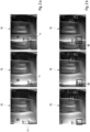
- Figure 2a are exemplary from left to right three temporally consecutive individual images of the video borescope 2 according to Figure 1 recorded video image of a single stage of the high-pressure turbine stage 87. Between the individual images shown there are two intermediate images, which are not taken into account in the processing described below and are therefore also not included in the representation of the Figure 2a can be omitted.
- Image recognition is carried out to identify possible defects.
- a suitably trained Faster-RCNN method is used for defect detection, which is trained in particular to detect notches and dents. All possible defects on the individual images according to Figure 2a are marked by a box 11.
- the individual images 10 according to Figure 2a are also used to determine the movement of the engine blades 90 in the image area of the video borescope 2.
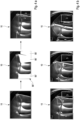
- each individual image 10 ⁇ is segmented into individual engine blade areas 90' using a Mask-RCNN method with Inception Feature Extractor ( Figure 3 , below).
- an exclusion region 12 is defined, indicated by dash-dot lines, in which no segmentation of the individual images 10' needs to take place, since there is a stationary element in this region 12 of the video image and it is therefore impossible for an engine blade 90 to be seen in this region.
- the speed and direction of movement of the engine blades 90 ⁇ can be determined in a simple manner using the engine blade areas 90', which in Figure 3 indicated by the vector 95 ⁇ .
- the intended segmentation of the individual images 10 ⁇ makes it possible, in addition to recording the movement of the engine blades 90, to determine the relative position of the individual engine blades 90 with respect to an arbitrarily selected initial engine blade 90", which is subsequently determined using the Figures 4a and b is explained in more detail.
- FIG 4a A single image 10" is initially displayed according to Figure 3 segmented, whereby - if a corresponding selection has not yet been made - one of the engine blade segments 90' is defined as the starting engine blade 90".
- the engine blades 90 or the engine blade segments 90' can be numbered starting from the starting engine blade 90".
- each engine blade segment 90' can be assigned a unique number which corresponds to counting the individual engine blades 90 or engine blade segments 90' (cf. Figure 4b ).
- the position of the individual engine blades 90 thus recorded makes it possible to control individual engine blades 90, the position of which has been recorded, by appropriately controlling the drive of the shaft 86 via the output 4 of the computer unit 3 and simultaneously checking according to Figure 4a, b be targeted in order to enable, for example, the follow-up inspection of a specific identified possible defect on the corresponding engine blades 90 using a live video image via Terminal 5.
- the detected movement of the engine blades 90 can be Figure 2a identified possible defects on the video image, more precisely on the individual images 10 used for motion detection.
- an optical image recognition is carried out for each of the individual images 10 in question, whereby - as in the present case - the Figure 2a
- the image capture described above can be used to identify possible defects or their results.
- a track 92 can be determined over the video image for the individual possible defects, provided they are found in all individual images, as shown in Figure 2b. If one of the traces 92 determined in this way has a length that is greater than a predetermined length, the possible defect forming the trace 92 can be identified as an actual defect, which can be documented in a suitable standardized manner.
- the results of verification by an inspector can be used to optimize image recognition of possible defects.
Landscapes
- Engineering & Computer Science (AREA)
- Physics & Mathematics (AREA)
- General Physics & Mathematics (AREA)
- Life Sciences & Earth Sciences (AREA)
- Analytical Chemistry (AREA)
- Pathology (AREA)
- Immunology (AREA)
- Health & Medical Sciences (AREA)
- General Health & Medical Sciences (AREA)
- Chemical & Material Sciences (AREA)
- Biochemistry (AREA)
- Computer Vision & Pattern Recognition (AREA)
- Quality & Reliability (AREA)
- Theoretical Computer Science (AREA)
- Textile Engineering (AREA)
- Signal Processing (AREA)
- Investigating Materials By The Use Of Optical Means Adapted For Particular Applications (AREA)
- Turbine Rotor Nozzle Sealing (AREA)
Claims (8)
- Procédé de détection automatisée de défauts lors d'une boroscopie de turbine, procédé dans lequel un vidéo-boroscope (2) est inséré dans une turbine (80) de manière à ce que, lorsqu'un arbre de turbine (83, 86) tourne, les pales de turbine (90), fixées à l'arbre de turbine, d'un étage de turbine (81, 84, 85, 87) sont déplacées l'une après l'autre à travers la zone d'image du vidéo-boroscope (2),
les étapes suivantes étant réalisées :- identifier un éventuel défaut d'une pale de turbine (90) par reconnaissance d'image sur la base d'une image individuelle (10) du vidéo-boroscope ;- détecter le mouvement des pales de turbine (90) dans la zone d'image du vidéo-boroscope par comparaison de deux images individuelles successives (10, 10') ;- suivre le défaut éventuel sur l'image vidéo suivant le mouvement détecté par reconnaissance d'image optique sur la base des images individuelles utilisées pour la détection de mouvement (10, 10') ;- si la trace (92) d'un éventuel défaut sur l'image vidéo correspond au mouvement détecté en direction et vitesse sur une longueur spécifiée, identifier le défaut éventuel comme un défaut réel. - Procédé selon la revendication 1,
caractérisé en ce que
la détection du mouvement des pales de turbine (90) est utilisée pour identifier la position des pales de turbine individuelles par rapport à une pale de turbine de départ choisie arbitrairement. - Procédé selon l'une des revendications précédentes,
caractérisé en ce que
le procédé comprend la commande du mouvement de rotation de l'axe de turbine. - Procédé selon l'une des revendications précédentes,
caractérisé en ce que
pour détecter le mouvement des pales de turbine, les images individuelles sont segmentées en zones de pale individuelles, de préférence à l'aide d'un procédé RCNN à masque, de préférence comprenant un extracteur de caractéristiques basé sur Inception. - Procédé selon la revendication 4,
caractérisé en ce que
des zones d'exclusion sont définies dans lesquelles aucune segmentation des images individuelles n'est effectuée. - Procédé selon l'une des revendications précédentes,
caractérisé en ce que
une direction de mouvement des pales de turbine est spécifiée dans la zone d'image du vidéo-boroscope. - Procédé selon l'une des revendications précédentes,
caractérisé en ce que
les éventuels défauts identifiables comprennent les entailles et les bosses. - Produit de programme d'ordinateur comprenant des parties de programme qui, lorsqu'elles sont chargées dans un ordinateur, sont conçues pour mettre en œuvre le procédé selon l'une des revendications 1 à 7.
Applications Claiming Priority (2)
| Application Number | Priority Date | Filing Date | Title |
|---|---|---|---|
| EP19194447.9A EP3786620A1 (fr) | 2019-08-29 | 2019-08-29 | Procédé et produit programme informatique pour la détection automatisée d'erreurs d'une boroscopie sur moteur |
| PCT/EP2020/073808 WO2021037885A1 (fr) | 2019-08-29 | 2020-08-26 | Procédé et produit-programme informatique de détection de défaut automatisée lors d'une boroscopie de mécanisme d'entraînement |
Publications (2)
| Publication Number | Publication Date |
|---|---|
| EP4022290A1 EP4022290A1 (fr) | 2022-07-06 |
| EP4022290B1 true EP4022290B1 (fr) | 2024-10-23 |
Family
ID=67956444
Family Applications (2)
| Application Number | Title | Priority Date | Filing Date |
|---|---|---|---|
| EP19194447.9A Withdrawn EP3786620A1 (fr) | 2019-08-29 | 2019-08-29 | Procédé et produit programme informatique pour la détection automatisée d'erreurs d'une boroscopie sur moteur |
| EP20761242.5A Active EP4022290B1 (fr) | 2019-08-29 | 2020-08-26 | Procédé et produit programme informatique pour la détection automatisée d'erreurs d'une boroscopie sur moteur |
Family Applications Before (1)
| Application Number | Title | Priority Date | Filing Date |
|---|---|---|---|
| EP19194447.9A Withdrawn EP3786620A1 (fr) | 2019-08-29 | 2019-08-29 | Procédé et produit programme informatique pour la détection automatisée d'erreurs d'une boroscopie sur moteur |
Country Status (5)
| Country | Link |
|---|---|
| US (1) | US12333699B2 (fr) |
| EP (2) | EP3786620A1 (fr) |
| JP (1) | JP2022546071A (fr) |
| CN (1) | CN114341931A (fr) |
| WO (1) | WO2021037885A1 (fr) |
Families Citing this family (3)
| Publication number | Priority date | Publication date | Assignee | Title |
|---|---|---|---|---|
| DE102021120899A1 (de) * | 2021-08-11 | 2023-03-02 | MTU Aero Engines AG | Verfahren zum abbilden einer oberfläche einer strömunsmaschine und detektieren einer schädigung |
| US20250200742A1 (en) * | 2022-03-17 | 2025-06-19 | Agency For Science, Technology And Research | Method and system for optical flow guided multiple-view defects information fusion |
| CN115096891B (zh) * | 2022-05-28 | 2024-05-07 | 国营芜湖机械厂 | 一种航空发动机叶片智能检查方法 |
Citations (2)
| Publication number | Priority date | Publication date | Assignee | Title |
|---|---|---|---|---|
| US20040183900A1 (en) * | 2003-03-20 | 2004-09-23 | Everest Vit | Method and system for automatically detecting defects in remote video inspection applications |
| US20160314571A1 (en) * | 2015-04-21 | 2016-10-27 | United Technologies Corporation | Method and System for Automated Inspection Utilizing A Multi-Modal Database |
Family Cites Families (18)
| Publication number | Priority date | Publication date | Assignee | Title |
|---|---|---|---|---|
| FR2626597B1 (fr) | 1988-02-01 | 1992-07-17 | Saint Gobain Isover | Panneau d'isolation thermique et acoustique |
| US6266138B1 (en) * | 1999-10-12 | 2001-07-24 | Perceptron, Inc. | System and method for detecting defects in a surface of a workpiece |
| JP4869699B2 (ja) | 2005-12-13 | 2012-02-08 | オリンパス株式会社 | 内視鏡装置 |
| US8791998B2 (en) * | 2009-07-31 | 2014-07-29 | Olympus Corporation | Image processing apparatus and method for displaying images |
| US8602722B2 (en) * | 2010-02-26 | 2013-12-10 | General Electric Company | System and method for inspection of stator vanes |
| CN202024969U (zh) | 2011-01-24 | 2011-11-02 | 江苏富兰肯光电科技有限公司 | 视频孔探仪 |
| CN102998363B (zh) | 2011-09-13 | 2016-01-20 | 沈阳黎明航空发动机(集团)有限责任公司 | 一种发动机叶片原位超声检测方法 |
| US9462183B2 (en) * | 2011-09-22 | 2016-10-04 | Siemens Energy, Inc. | Trigger for blade imaging based on a controller |
| US8744166B2 (en) | 2011-11-03 | 2014-06-03 | United Technologies Corporation | System and method for multiple simultaneous automated defect detection |
| US9471057B2 (en) * | 2011-11-09 | 2016-10-18 | United Technologies Corporation | Method and system for position control based on automated defect detection feedback |
| JP2014032363A (ja) * | 2012-08-06 | 2014-02-20 | Olympus Corp | 内視鏡装置 |
| JP6238555B2 (ja) * | 2013-04-24 | 2017-11-29 | オリンパス株式会社 | 内視鏡システム |
| JP6802794B2 (ja) * | 2015-07-24 | 2020-12-23 | オリンパス株式会社 | 補正情報生成装置及び回転する検査対象の画像補正のための補正情報生成方法 |
| US20180033129A1 (en) * | 2016-07-28 | 2018-02-01 | United Technologies Corporation | Systems and methods for indexing and detecting components |
| CN108375628B (zh) | 2016-09-18 | 2022-07-26 | 中国石油大学(华东) | 一种周向电磁场管道内壁裂纹检测系统及定量评估方法 |
| CN108167078A (zh) | 2017-12-26 | 2018-06-15 | 中国航发四川燃气涡轮研究院 | 一种配合航空发动机孔探检查的遥控自动盘车装置 |
| CN108897925B (zh) | 2018-06-11 | 2020-09-08 | 华中科技大学 | 一种基于铸件缺陷预测模型的铸造工艺参数优化方法 |
| US12125212B2 (en) * | 2020-12-23 | 2024-10-22 | Intel Corporation | Methods and apparatus for high-fidelity vision tasks using deep neural networks |
-
2019
- 2019-08-29 EP EP19194447.9A patent/EP3786620A1/fr not_active Withdrawn
-
2020
- 2020-08-26 EP EP20761242.5A patent/EP4022290B1/fr active Active
- 2020-08-26 US US17/638,215 patent/US12333699B2/en active Active
- 2020-08-26 CN CN202080060615.7A patent/CN114341931A/zh active Pending
- 2020-08-26 JP JP2022513363A patent/JP2022546071A/ja active Pending
- 2020-08-26 WO PCT/EP2020/073808 patent/WO2021037885A1/fr not_active Ceased
Patent Citations (2)
| Publication number | Priority date | Publication date | Assignee | Title |
|---|---|---|---|---|
| US20040183900A1 (en) * | 2003-03-20 | 2004-09-23 | Everest Vit | Method and system for automatically detecting defects in remote video inspection applications |
| US20160314571A1 (en) * | 2015-04-21 | 2016-10-27 | United Technologies Corporation | Method and System for Automated Inspection Utilizing A Multi-Modal Database |
Also Published As
| Publication number | Publication date |
|---|---|
| US12333699B2 (en) | 2025-06-17 |
| EP4022290A1 (fr) | 2022-07-06 |
| EP3786620A1 (fr) | 2021-03-03 |
| JP2022546071A (ja) | 2022-11-02 |
| CN114341931A (zh) | 2022-04-12 |
| US20220245785A1 (en) | 2022-08-04 |
| WO2021037885A1 (fr) | 2021-03-04 |
Similar Documents
| Publication | Publication Date | Title |
|---|---|---|
| EP2761140B1 (fr) | Système endoscopique et procédé associé de contrôle de turbines à gaz | |
| EP3912127B1 (fr) | Procédé et dispositif d'inspection de composants difficiles à atteindre | |
| EP4022290B1 (fr) | Procédé et produit programme informatique pour la détection automatisée d'erreurs d'une boroscopie sur moteur | |
| EP2715322B1 (fr) | Procédé et dispositif pour le contrôle des fissures d'une pièce structurale d'avion ou de turbine à gaz | |
| EP3432266A1 (fr) | Procédé et dispositif de détection de défauts | |
| EP3956736B1 (fr) | Procédé mis en oeuvre par ordinateur pour la détermination de défauts d'un objet fabriqué au moyen d'un processus de fabrication additive | |
| EP4288768B1 (fr) | Procédé pour contrôler un composant d'une turbomachine | |
| DE112017002965T5 (de) | Verfahren und System zum Abwinkeln einer visuellen Inspektionsvorrichtung | |
| EP3911944B1 (fr) | Procédé et dispositif d'inspection au boroscope | |
| DE102015009728B4 (de) | Probabilistische Fehlererkennung in verlegten Faserbändchen | |
| DE102018214307B4 (de) | System und Verfahren zur Qualitätsprüfung bei der Herstellung von Einzelteilen | |
| WO2025073314A1 (fr) | Procédé pour examiner un élément structural d'une turbomachine et dispositif correspondant pour examiner un tel élément structural | |
| EP3885078A1 (fr) | Balayage de surface hyperspectrale d'un corps | |
| EP1988506A2 (fr) | Procédé de détermination automatique de la zone de contrôle, procédé de contrôle et système de contrôle | |
| EP2345004B1 (fr) | Procédé et système de contrôle pour réaliser un contrôle optique du contour d'un objet | |
| DE102022204406A1 (de) | Verfahren zum Klassifizieren und/oder zur Regression von Eingangssignalen unter Zuhilfenahme einer Gram-Matrix-Variante | |
| DE102017122146A1 (de) | Kombiniertes Messsystem zur Augenbestimmung und Verfahren zur kombinierten Augenbestimmung | |
| DE102018112910B4 (de) | Herstellungsverfahren für eine Antriebseinrichtung und Prüfeinrichtung | |
| EP3173618B1 (fr) | Procédé de contrôle d'éléments d'éoliennes, en particulier pales de rotor | |
| EP2353143B1 (fr) | Procédé et système de contrôle pour réaliser un contrôle optique d'un objet | |
| EP4443141A1 (fr) | Système et procédé de contrôle de défauts de surface sur un objet à contrôler | |
| EP4693219A1 (fr) | Procédé de commande d'un traitement d'un tronçon de câble, unité de commande, dispositif de traitement de câble, procédé d'apprentissage d'un classificateur et dispositif d'entraînement | |
| DE102024209891A1 (de) | Verfahren zum Bereitstellen eines Trainings- und eines Testdatensatzes | |
| DE102021202511A1 (de) | Verfahren zum Erzeugen von dreidimensionalen Trainingsdaten für eine Erkennungsvorrichtung zum Erkennen von Alarmobjekten in Gepäckstücken | |
| EP1901230A1 (fr) | Procédé d'inspection superficielle automatique d'un corps mobile |
Legal Events
| Date | Code | Title | Description |
|---|---|---|---|
| STAA | Information on the status of an ep patent application or granted ep patent |
Free format text: STATUS: UNKNOWN |
|
| STAA | Information on the status of an ep patent application or granted ep patent |
Free format text: STATUS: THE INTERNATIONAL PUBLICATION HAS BEEN MADE |
|
| PUAI | Public reference made under article 153(3) epc to a published international application that has entered the european phase |
Free format text: ORIGINAL CODE: 0009012 |
|
| STAA | Information on the status of an ep patent application or granted ep patent |
Free format text: STATUS: REQUEST FOR EXAMINATION WAS MADE |
|
| 17P | Request for examination filed |
Effective date: 20220304 |
|
| AK | Designated contracting states |
Kind code of ref document: A1 Designated state(s): AL AT BE BG CH CY CZ DE DK EE ES FI FR GB GR HR HU IE IS IT LI LT LU LV MC MK MT NL NO PL PT RO RS SE SI SK SM TR |
|
| REG | Reference to a national code |
Ref country code: HK Ref legal event code: DE Ref document number: 40072196 Country of ref document: HK |
|
| DAV | Request for validation of the european patent (deleted) | ||
| DAX | Request for extension of the european patent (deleted) | ||
| P01 | Opt-out of the competence of the unified patent court (upc) registered |
Effective date: 20230516 |
|
| GRAP | Despatch of communication of intention to grant a patent |
Free format text: ORIGINAL CODE: EPIDOSNIGR1 |
|
| STAA | Information on the status of an ep patent application or granted ep patent |
Free format text: STATUS: GRANT OF PATENT IS INTENDED |
|
| INTG | Intention to grant announced |
Effective date: 20240628 |
|
| GRAS | Grant fee paid |
Free format text: ORIGINAL CODE: EPIDOSNIGR3 |
|
| GRAA | (expected) grant |
Free format text: ORIGINAL CODE: 0009210 |
|
| STAA | Information on the status of an ep patent application or granted ep patent |
Free format text: STATUS: THE PATENT HAS BEEN GRANTED |
|
| AK | Designated contracting states |
Kind code of ref document: B1 Designated state(s): AL AT BE BG CH CY CZ DE DK EE ES FI FR GB GR HR HU IE IS IT LI LT LU LV MC MK MT NL NO PL PT RO RS SE SI SK SM TR |
|
| REG | Reference to a national code |
Ref country code: GB Ref legal event code: FG4D Free format text: NOT ENGLISH |
|
| REG | Reference to a national code |
Ref country code: CH Ref legal event code: EP |
|
| REG | Reference to a national code |
Ref country code: DE Ref legal event code: R096 Ref document number: 502020009575 Country of ref document: DE |
|
| REG | Reference to a national code |
Ref country code: IE Ref legal event code: FG4D Free format text: LANGUAGE OF EP DOCUMENT: GERMAN |
|
| REG | Reference to a national code |
Ref country code: LT Ref legal event code: MG9D |
|
| REG | Reference to a national code |
Ref country code: NL Ref legal event code: MP Effective date: 20241023 |
|
| PG25 | Lapsed in a contracting state [announced via postgrant information from national office to epo] |
Ref country code: NL Free format text: LAPSE BECAUSE OF FAILURE TO SUBMIT A TRANSLATION OF THE DESCRIPTION OR TO PAY THE FEE WITHIN THE PRESCRIBED TIME-LIMIT Effective date: 20241023 |
|
| PG25 | Lapsed in a contracting state [announced via postgrant information from national office to epo] |
Ref country code: NL Free format text: LAPSE BECAUSE OF FAILURE TO SUBMIT A TRANSLATION OF THE DESCRIPTION OR TO PAY THE FEE WITHIN THE PRESCRIBED TIME-LIMIT Effective date: 20241023 |
|
| PG25 | Lapsed in a contracting state [announced via postgrant information from national office to epo] |
Ref country code: PT Free format text: LAPSE BECAUSE OF FAILURE TO SUBMIT A TRANSLATION OF THE DESCRIPTION OR TO PAY THE FEE WITHIN THE PRESCRIBED TIME-LIMIT Effective date: 20250224 Ref country code: HR Free format text: LAPSE BECAUSE OF FAILURE TO SUBMIT A TRANSLATION OF THE DESCRIPTION OR TO PAY THE FEE WITHIN THE PRESCRIBED TIME-LIMIT Effective date: 20241023 Ref country code: IS Free format text: LAPSE BECAUSE OF FAILURE TO SUBMIT A TRANSLATION OF THE DESCRIPTION OR TO PAY THE FEE WITHIN THE PRESCRIBED TIME-LIMIT Effective date: 20250223 |
|
| PG25 | Lapsed in a contracting state [announced via postgrant information from national office to epo] |
Ref country code: FI Free format text: LAPSE BECAUSE OF FAILURE TO SUBMIT A TRANSLATION OF THE DESCRIPTION OR TO PAY THE FEE WITHIN THE PRESCRIBED TIME-LIMIT Effective date: 20241023 |
|
| PG25 | Lapsed in a contracting state [announced via postgrant information from national office to epo] |
Ref country code: BG Free format text: LAPSE BECAUSE OF FAILURE TO SUBMIT A TRANSLATION OF THE DESCRIPTION OR TO PAY THE FEE WITHIN THE PRESCRIBED TIME-LIMIT Effective date: 20241023 |
|
| PG25 | Lapsed in a contracting state [announced via postgrant information from national office to epo] |
Ref country code: ES Free format text: LAPSE BECAUSE OF FAILURE TO SUBMIT A TRANSLATION OF THE DESCRIPTION OR TO PAY THE FEE WITHIN THE PRESCRIBED TIME-LIMIT Effective date: 20241023 |
|
| PG25 | Lapsed in a contracting state [announced via postgrant information from national office to epo] |
Ref country code: NO Free format text: LAPSE BECAUSE OF FAILURE TO SUBMIT A TRANSLATION OF THE DESCRIPTION OR TO PAY THE FEE WITHIN THE PRESCRIBED TIME-LIMIT Effective date: 20250123 |
|
| PG25 | Lapsed in a contracting state [announced via postgrant information from national office to epo] |
Ref country code: LV Free format text: LAPSE BECAUSE OF FAILURE TO SUBMIT A TRANSLATION OF THE DESCRIPTION OR TO PAY THE FEE WITHIN THE PRESCRIBED TIME-LIMIT Effective date: 20241023 Ref country code: GR Free format text: LAPSE BECAUSE OF FAILURE TO SUBMIT A TRANSLATION OF THE DESCRIPTION OR TO PAY THE FEE WITHIN THE PRESCRIBED TIME-LIMIT Effective date: 20250124 |
|
| PG25 | Lapsed in a contracting state [announced via postgrant information from national office to epo] |
Ref country code: PL Free format text: LAPSE BECAUSE OF FAILURE TO SUBMIT A TRANSLATION OF THE DESCRIPTION OR TO PAY THE FEE WITHIN THE PRESCRIBED TIME-LIMIT Effective date: 20241023 |
|
| PG25 | Lapsed in a contracting state [announced via postgrant information from national office to epo] |
Ref country code: RS Free format text: LAPSE BECAUSE OF FAILURE TO SUBMIT A TRANSLATION OF THE DESCRIPTION OR TO PAY THE FEE WITHIN THE PRESCRIBED TIME-LIMIT Effective date: 20250123 |
|
| PG25 | Lapsed in a contracting state [announced via postgrant information from national office to epo] |
Ref country code: SM Free format text: LAPSE BECAUSE OF FAILURE TO SUBMIT A TRANSLATION OF THE DESCRIPTION OR TO PAY THE FEE WITHIN THE PRESCRIBED TIME-LIMIT Effective date: 20241023 |
|
| PG25 | Lapsed in a contracting state [announced via postgrant information from national office to epo] |
Ref country code: DK Free format text: LAPSE BECAUSE OF FAILURE TO SUBMIT A TRANSLATION OF THE DESCRIPTION OR TO PAY THE FEE WITHIN THE PRESCRIBED TIME-LIMIT Effective date: 20241023 |
|
| PG25 | Lapsed in a contracting state [announced via postgrant information from national office to epo] |
Ref country code: EE Free format text: LAPSE BECAUSE OF FAILURE TO SUBMIT A TRANSLATION OF THE DESCRIPTION OR TO PAY THE FEE WITHIN THE PRESCRIBED TIME-LIMIT Effective date: 20241023 |
|
| PG25 | Lapsed in a contracting state [announced via postgrant information from national office to epo] |
Ref country code: RO Free format text: LAPSE BECAUSE OF FAILURE TO SUBMIT A TRANSLATION OF THE DESCRIPTION OR TO PAY THE FEE WITHIN THE PRESCRIBED TIME-LIMIT Effective date: 20241023 |
|
| REG | Reference to a national code |
Ref country code: DE Ref legal event code: R097 Ref document number: 502020009575 Country of ref document: DE |
|
| PG25 | Lapsed in a contracting state [announced via postgrant information from national office to epo] |
Ref country code: SK Free format text: LAPSE BECAUSE OF FAILURE TO SUBMIT A TRANSLATION OF THE DESCRIPTION OR TO PAY THE FEE WITHIN THE PRESCRIBED TIME-LIMIT Effective date: 20241023 |
|
| PG25 | Lapsed in a contracting state [announced via postgrant information from national office to epo] |
Ref country code: CZ Free format text: LAPSE BECAUSE OF FAILURE TO SUBMIT A TRANSLATION OF THE DESCRIPTION OR TO PAY THE FEE WITHIN THE PRESCRIBED TIME-LIMIT Effective date: 20241023 |
|
| PG25 | Lapsed in a contracting state [announced via postgrant information from national office to epo] |
Ref country code: IT Free format text: LAPSE BECAUSE OF FAILURE TO SUBMIT A TRANSLATION OF THE DESCRIPTION OR TO PAY THE FEE WITHIN THE PRESCRIBED TIME-LIMIT Effective date: 20241023 |
|
| PLBE | No opposition filed within time limit |
Free format text: ORIGINAL CODE: 0009261 |
|
| STAA | Information on the status of an ep patent application or granted ep patent |
Free format text: STATUS: NO OPPOSITION FILED WITHIN TIME LIMIT |
|
| PG25 | Lapsed in a contracting state [announced via postgrant information from national office to epo] |
Ref country code: SE Free format text: LAPSE BECAUSE OF FAILURE TO SUBMIT A TRANSLATION OF THE DESCRIPTION OR TO PAY THE FEE WITHIN THE PRESCRIBED TIME-LIMIT Effective date: 20241023 |
|
| 26N | No opposition filed |
Effective date: 20250724 |
|
| PGFP | Annual fee paid to national office [announced via postgrant information from national office to epo] |
Ref country code: DE Payment date: 20250819 Year of fee payment: 6 |
|
| PGFP | Annual fee paid to national office [announced via postgrant information from national office to epo] |
Ref country code: GB Payment date: 20250822 Year of fee payment: 6 |
|
| PGFP | Annual fee paid to national office [announced via postgrant information from national office to epo] |
Ref country code: FR Payment date: 20250821 Year of fee payment: 6 |
|
| PGFP | Annual fee paid to national office [announced via postgrant information from national office to epo] |
Ref country code: IE Payment date: 20250821 Year of fee payment: 6 |
|
| REG | Reference to a national code |
Ref country code: CH Ref legal event code: H13 Free format text: ST27 STATUS EVENT CODE: U-0-0-H10-H13 (AS PROVIDED BY THE NATIONAL OFFICE) Effective date: 20260324 |
|
| PG25 | Lapsed in a contracting state [announced via postgrant information from national office to epo] |
Ref country code: MC Free format text: LAPSE BECAUSE OF FAILURE TO SUBMIT A TRANSLATION OF THE DESCRIPTION OR TO PAY THE FEE WITHIN THE PRESCRIBED TIME-LIMIT Effective date: 20241023 |
|
| PG25 | Lapsed in a contracting state [announced via postgrant information from national office to epo] |
Ref country code: LU Free format text: LAPSE BECAUSE OF NON-PAYMENT OF DUE FEES Effective date: 20250826 |
|
| PG25 | Lapsed in a contracting state [announced via postgrant information from national office to epo] |
Ref country code: CH Free format text: LAPSE BECAUSE OF NON-PAYMENT OF DUE FEES Effective date: 20250831 |