EP4023449A1 - Procédé de thermique directe multicolore et imprimante pour impression thermique directe multicolore - Google Patents
Procédé de thermique directe multicolore et imprimante pour impression thermique directe multicolore Download PDFInfo
- Publication number
- EP4023449A1 EP4023449A1 EP20218028.7A EP20218028A EP4023449A1 EP 4023449 A1 EP4023449 A1 EP 4023449A1 EP 20218028 A EP20218028 A EP 20218028A EP 4023449 A1 EP4023449 A1 EP 4023449A1
- Authority
- EP
- European Patent Office
- Prior art keywords
- direct thermal
- printing
- paper
- color
- temperature
- Prior art date
- Legal status (The legal status is an assumption and is not a legal conclusion. Google has not performed a legal analysis and makes no representation as to the accuracy of the status listed.)
- Granted
Links
Images


Classifications
-
- B—PERFORMING OPERATIONS; TRANSPORTING
- B41—PRINTING; LINING MACHINES; TYPEWRITERS; STAMPS
- B41M—PRINTING, DUPLICATING, MARKING, OR COPYING PROCESSES; COLOUR PRINTING
- B41M5/00—Duplicating or marking methods; Sheet materials for use therein
- B41M5/26—Thermography ; Marking by high energetic means, e.g. laser otherwise than by burning, and characterised by the material used
- B41M5/34—Multicolour thermography
-
- B—PERFORMING OPERATIONS; TRANSPORTING
- B41—PRINTING; LINING MACHINES; TYPEWRITERS; STAMPS
- B41J—TYPEWRITERS; SELECTIVE PRINTING MECHANISMS, i.e. MECHANISMS PRINTING OTHERWISE THAN FROM A FORME; CORRECTION OF TYPOGRAPHICAL ERRORS
- B41J2/00—Typewriters or selective printing mechanisms characterised by the printing or marking process for which they are designed
- B41J2/315—Typewriters or selective printing mechanisms characterised by the printing or marking process for which they are designed characterised by selective application of heat to a heat sensitive printing or impression-transfer material
- B41J2/32—Typewriters or selective printing mechanisms characterised by the printing or marking process for which they are designed characterised by selective application of heat to a heat sensitive printing or impression-transfer material using thermal heads
- B41J2/325—Typewriters or selective printing mechanisms characterised by the printing or marking process for which they are designed characterised by selective application of heat to a heat sensitive printing or impression-transfer material using thermal heads by selective transfer of ink from ink carrier, e.g. from ink ribbon or sheet
-
- B—PERFORMING OPERATIONS; TRANSPORTING
- B41—PRINTING; LINING MACHINES; TYPEWRITERS; STAMPS
- B41J—TYPEWRITERS; SELECTIVE PRINTING MECHANISMS, i.e. MECHANISMS PRINTING OTHERWISE THAN FROM A FORME; CORRECTION OF TYPOGRAPHICAL ERRORS
- B41J2/00—Typewriters or selective printing mechanisms characterised by the printing or marking process for which they are designed
- B41J2/315—Typewriters or selective printing mechanisms characterised by the printing or marking process for which they are designed characterised by selective application of heat to a heat sensitive printing or impression-transfer material
- B41J2/32—Typewriters or selective printing mechanisms characterised by the printing or marking process for which they are designed characterised by selective application of heat to a heat sensitive printing or impression-transfer material using thermal heads
- B41J2/335—Structure of thermal heads
-
- B—PERFORMING OPERATIONS; TRANSPORTING
- B41—PRINTING; LINING MACHINES; TYPEWRITERS; STAMPS
- B41M—PRINTING, DUPLICATING, MARKING, OR COPYING PROCESSES; COLOUR PRINTING
- B41M2205/00—Printing methods or features related to printing methods; Location or type of the layers
- B41M2205/04—Direct thermal recording [DTR]
-
- B—PERFORMING OPERATIONS; TRANSPORTING
- B41—PRINTING; LINING MACHINES; TYPEWRITERS; STAMPS
- B41M—PRINTING, DUPLICATING, MARKING, OR COPYING PROCESSES; COLOUR PRINTING
- B41M2205/00—Printing methods or features related to printing methods; Location or type of the layers
- B41M2205/42—Multiple imaging layers
Definitions
- the present invention relates to a method for multicolor, in particular two-color direct thermal printing and a printer for multicolor, in particular two-color direct thermal printing.
- Direct thermal printing papers that change color to different colors in response to different temperatures are known to those skilled in the art.
- the direct thermal printing paper KLRB 46B from Kanzan is a paper that turns red at a temperature of 75°C to 80°C and turns black at a temperature of 95°C to 105°C.
- the EP1866161B1 also shows a two-color direct thermal printing paper.
- the EP1866161B1 also shows a printer for printing on such direct thermal printing paper, which comprises two print heads, the first print head applying a temperature to the direct thermal printing paper that triggers discoloration in the first color and the second print head applying a temperature to the direct thermal printing paper applied, which triggers a discoloration in the second color. From the EP3175993B1 a direct thermal printing paper is known which can be used for three-color printing.
- Direct thermal printers with a print head whose thermocouples can generate two different temperatures are known to those skilled in the art DE60207488T2 and the DE60036515T2 known. In this way, a two-color print can be produced on the thermal direct printing paper. These printheads and their controls are expensive and complex.
- the object of the invention is to propose a less expensive direct thermal printer for multicolor direct thermal printing and a method for operating a direct thermal printer for multicolor direct thermal printing.
- the two-color direct thermal printing paper in particular the Kanzan paper already mentioned, turns red in a first temperature range of 75°C to 80°C and black at a temperature of 95°C to 105°C when heat is applied. Since the paper slides under the print head and the heat sources are covered with a protective layer or glass, for example, and the paper as linerless paper has a protective layer, in particular silicone layer, over the thermoreactive one, the heat sources during printing may have to be slightly higher temperatures than those above mentioned discoloration temperatures.
- the direct thermal printing paper is intended to be supplied with two discrete temperatures for two-color printing. However, direct thermal printheads, whose heat sources can generate two different temperatures, are technically complex and sometimes unreliable.
- the method according to the invention has the advantage that only one discrete temperature, the printing temperature, has to be generated at the heat sources. If several adjacent pixels are heated to the printing temperature, the printing temperature is transferred and the thermal direct printing paper under these pixels heats up to the higher temperature range in which the second color is trained. If, from a group of adjacent heat sources, i.e. from a group of adjacent pixels, some are heated to the printing temperature and others are not, an average temperature is formed that is transferred to the direct thermal printing paper, which is in the lower temperature range of direct thermal printing paper falls and forms the first color. It can be observed that the active heat sources, i.e. the heat sources heated to the printing temperature, form pixels in the second color on the direct thermal printing paper.
- spots in the first color form because the temperature on the thermal direct printing paper in these areas drops somewhat and corresponds to the lower temperature range.
- the process makes use of the fact that a point heat source radiates heat in the immediate vicinity.
- a combination of active and inactive heat sources creates a pixel pattern on the direct thermal printing paper that has a few pixels in the second color and around them pixels in the first color. Due to the small pixel size, however, the human eye cannot perceive the individual pixels. Rather, depending on the relationship between active and inactive heat sources and their geometric arrangement, the area appears as an area in the first color.
- the direct thermal printing paper includes a thermoreactive layer that can form both the first and the second color.
- a direct thermal printing paper is also a paper that includes a first thermoreactive layer that can form a first color and a second thermoreactive layer that is arranged above or below it and that can form a second color.
- a direct thermal printing paper is also included, which has, for example, a flat coating of one color and a non-transparent covering layer above it, with the covering layer being exposed when heat is applied becomes transparent and the colored coating becomes visible. In this way, both the first color and the second color can be formed.
- direct thermal printing papers that can form more than two colors are also included.
- the unprinted direct thermal printing paper is usually white or has a whitish tint. This is not to be understood as a first or second color within the meaning of the invention.
- the second color is black.
- the first color is red.
- the first color and the second color mean a reaction of the thermoreactive layer.
- the thermo-responsive layer changes color.
- color effects can be achieved, such as a light red area or a dark red area.
- these consist of individual red, white and black pixels and are not to be regarded as separate colors within the meaning of this disclosure.
- the printing temperature is equal to or higher than the second temperature.
- the heat source must transfer heat to the paper at the temperature of the higher temperature range. This is the second temperature. Due to the effects that can occur due to the protective layer on the print head and the protective layer on the direct thermal printing paper, the printing temperature may have to be slightly higher than the second temperature.
- the step of moving the direct thermal printing paper line by line occurs during a line time from a line n to a next line n+1.
- the movement of the direct thermal printing paper is continuous, ie the paper is moved past the print head at a constant or almost constant speed.
- the Stepping the direct thermal paper that is, the direct thermal paper is moved to the next line n+1 and stopped until the line time expires, and then advanced to line n+2.
- the area on the direct thermal printing paper when printing an area, comprises multiple rows and multiple columns.
- the rows from the print head's point of view correspond to a time when this row is under the heat sources of the print head.
- the columns of the area correspond to certain heat sources of the print head as seen from the print head. If an area on the thermal direct printing paper is printed in the second color, all heat sources that correspond to the columns of the rows are heated to the printing temperature over the times that correspond to the rows of the area. All heat sources that correspond to the projection on the surface on the direct thermal printing paper are heated to the printing temperature and the surface changes color to the second color.
- the area including multiple rows (n, n+1, n+2) and multiple columns, while printing the multiple rows (n, n+ 1, n+2), all heat sources corresponding to the multiple columns heated to the printing temperature.
- the surface is printed in the first color
- one part of the heat sources mentioned in the previous paragraph must be heated to the printing temperature (active heat sources) and another part is not heated (inactive heat sources), i.e. the other Some of the heat sources are not controlled electrically.
- active heat sources the area including multiple rows (n, n+1, n+2) and multiple columns, while printing the multiple rows (n, n+ 1, n+2) from the heat sources corresponding to the multiple columns, a portion is heated to the printing temperature, so that the projection of the heat sources onto the surface has a regular grid corresponds to active and inactive heat sources, where there are as many or more inactive than active heat sources.
- a pure print in the first color ie an area that only has pixels in the first color
- the human eye perceives the area in the first color when the pixels of the first color and the pixels of the second color are arranged in a regular grid and the pixels of the first color predominate. Therefore, there must be as many or more inactive heat sources in the grid on the projection of the area than active heat sources.
- the heat sources corresponding to the multiple columns are heated to the printing temperature in such a way that the projection of the heat sources onto the surface has a regular Grid of active and inactive heat sources corresponds.
- the paper color is white, although the white can have a slight reddish tinge.
- the grid is arranged in such a way that the distance between two heat sources that are heated to the printing temperature exceeds a minimum distance in row direction and column direction, a white pixel appears on the surface. It is thus possible to create a grid that represents an overlay of pixels in the first color, in the second color and white pixels.
- the second color is black. Hues in the first color, particularly red, can be printed at different levels of lightness. A screen containing more active heat sources will print a darker shade of the first color on the direct thermal paper than a screen with fewer active heat sources. Are For example, the first color is red and the second color is black.
- red tones can be generated in different brightness levels, from a bright red with a large proportion of white to a dark red that fades into black .
- the fact that the printing of red pixels by the inventive method always causes a black pixel in the middle, which is surrounded by red pixels, means that there can be no pure red area and an area perceived by the human eye as a red area from a plurality of red pixels and a smaller number of black pixels and in particular also a smaller number of white pixels.
- the regular raster is a raster which is repeated in rows and/or columns or is arranged obliquely or alternately. Different effects can be achieved with different regular grids and in particular different brightnesses of the first color can be printed.
- a repeating grid over several pixels in the row direction and in the column direction results in a small area with a specific lightness of the first color.
- Various geometric shapes can be assembled from many small areas, resulting in many shapes and a large degree of freedom for prints in the first and second color.
- the direct thermal printing paper is linerless paper.
- the direct thermal printing paper comprises a silicone layer on the upper side.
- Linerless paper is paper made from a continuous strip that does not include a carrier tape.
- the paper layer on the back has an adhesive material, in particular an adhesive coating, in order to be able to stick labels that have been separated from the continuous strip to an object. So that the label web does not stick to itself when it is rolled up into a continuous roll, the top of the paper has a silicone layer from which the adhesive material can be removed is.
- This silicone layer on the thermal direct printing paper has the advantage in the method according to the invention that the heat from the heat source is distributed somewhat in the silicone layer and not only penetrates the paper at certain points under the heat source, but also in its vicinity.
- an active heat source is electrically controlled by the controller during a printing interval.
- the pressure interval is divided into a saturation interval and a subsequent cooling interval.
- the saturation interval begins with a wait time.
- the heat source is only supplied with electricity in the time after the waiting time has elapsed until the end of the saturation interval.
- the waiting time in row n depends on the status of the heat source in at least one previous row n-1.
- the print interval corresponds to line time.
- the saturation interval is the same for all heat sources of the printhead.
- the waiting time can be selected differently for each heat source and depends on the previous state of this heat source.
- the printhead includes a temperature sensor on its surface. Depending on the temperature of the temperature sensor, the saturation interval, which is the same for all heat sources, is determined. For example, a longer saturation interval is chosen in a very cold environment than in a warm environment.
- a direct thermal printer for printing direct thermal printing paper comprises at least one thermoreactive layer. At least two colors can be formed with the at least one thermoreactive layer. A first color is formed upon application of a first temperature and a second color is formed upon application of a second temperature. The second temperature is higher than the first temperature.
- the direct thermal printer includes a transport roller that moves the direct thermal printing paper along a paper path from a paper input to a paper output.
- the direct thermal printer comprises a print head, which comprises heat sources which are arranged next to one another transversely to the paper path and can be controlled electrically. The print head applies heat to the thermal direct printing paper at specific points.
- the direct thermal printer includes a control device that controls a rotation of the transport roller and uses the transport roller to move the direct thermal printing paper line by line along the print head in the direction of a printing direction.
- Each heat source of the print head is electrically connected to the controller and can be heated to a printing temperature.
- the control device is designed to heat selected heat sources of the print head to the printing temperature in each line of the direct thermal printing paper.
- a plurality of adjacent heat sources are heated to the printing temperature at the points where the second color is to be formed on the direct thermal printing paper.
- a portion is heated to the printing temperature by a plurality of adjacent heat sources and the other portion of the heat sources is not heated.
- the pressure bar is a pressure bar based on thick film technology.
- Examples of pressure bars based on thick film technology are the KD2004-DC91B from Rohm or the KPW-104-BZR from Kyocera.
- the pressure bar is a pressure bar based on thin-film technology.
- the printing temperature is equal to or higher than the second temperature.
- the transport roller is a pressure roller that presses the direct thermal printing paper against the printhead.
- the direct thermal printer is a linerless printer and the direct thermal printing paper is a continuous paper made of linerless paper, which is provided with a silicone layer on its upper side.
- the controller controls the transport roller so that the transport roller moves the direct thermal printing paper from a line n to a next line n+1 during a line time, the movement being stepwise or continuous during the line time.
- the printer includes a paper path that leads from a paper receptacle 46, in which a paper roll 32 is mounted, via a print roller 40 and a print head 42 to a paper output 44.
- the paper is wound onto a paper roll 32 in the form of an endless strip of direct thermal printing paper 34 .
- the direct thermal printing paper 34 comprises an underside to which an adhesive layer is applied and an upper side 36 to which a silicone layer is applied.
- the pressure roller 40 serves as a transport roller for the continuous strip of direct thermal printing paper 34. The pressure roller presses the direct thermal printing paper 34 with its upper side 36 against the print head 42.
- the direct thermal printer 30 comprises a control device 48 which is electrically connected to the print head 42 and the platen 40.
- the control device 48 controls the print roller 40, which moves the direct thermal printing paper 34 past the print head 42 line by line.
- the control device 48 also controls the print head 42, in particular the control device 48 controls the heat sources 52 of the print head 42, so that the desired print results in line n, which is located just below the print head 42 due to the transport of the direct thermal printing paper 34 .
- the coordinated control of the print roller 40 and the print head 42 by the control device 48 results in line-by-line printing on the thermal direct printing paper 34.
- the pixels in the column direction correspond to the individual heat sources 52
- the pixels in the row direction n, n+1, n +2 correspond to the respective point in time t0, tz, 2tz at which the corresponding line n, n+1, n+2 is located under the print head 42.
- the controller 48 is configured to heat or not heat each individual heat source 52 to a printing temperature.
- the print head 42 shows a print head 42 in a view from below.
- the direct thermal paper 34 is moved past the print head 42 line by line along a printing direction 60 by the print roller 40 .
- the print head 42 comprises a print field 56 with a multiplicity of heat sources 52 arranged next to one another.
- the heat sources emit heat at specific points.
- the spacing 54 between the heat sources 52 is illustrated in FIG 2 presented relatively broadly. In practice, the distance 54 between two adjacent heat sources 52 is very small. It should in 2 only indicated that each heat source 52 is attached independently of the adjacent heat sources 52 and can be controlled separately by the control device.
- the width of the print field 56 corresponds at least to the maximum that can be printed
- the pressure field 56 is covered with a cover that preferably conducts heat well, in order to protect the heat sources 52 from mechanical damage.
- the heat sources 52 are in particular heating resistors.
- the print head 42 includes a temperature sensor 58 which measures the temperature 58 at the top of the print head and passes it on to the control device 48 as a parameter.
- Typical values for the direct thermal paper width are 60 mm, 80 mm or 120 mm.
- a typical resolution of applicant's linerless direct thermal printing paper is 200 dpi, in particular 300 dpi.
- a typical printing speed, ie a typical transport speed at which the paper is moved along under the print head, is 100 mm/s to 400 mm/s, in particular 120 mm/s, 150 mm/s or 250 mm/s.
- the print head comprises at least 960 heat sources 52.
- the printing roller With a resolution of 300 dpi, 12 dots/mm, i.e. 12 lines/mm, are required in the transport direction. At a typical transport speed, i.e. printing speed, of 150 mm/s, the printing roller has to do 1800 lines/s, i.e. 1800 steps per second.
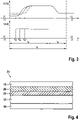
- FIG. 3 shows a schematic diagram for the activation of a heat source 52 by the control device 48 (lower part) and the associated heat development at the heat source 52 (upper part).
- a pressure interval ti is shown.
- a line n of the direct thermal printing paper is printed during a printing interval ti.
- the print interval ti is typically at least 300 ⁇ s long. In any case, the print interval ti must not be longer than a line time tz and is in particular the same length as a line time tz.
- the direct thermal printing paper 34 is through the platen roller 40 has been moved from line n-1 to line n.
- the direct thermal printing paper 34 is on line n at the beginning of the printing interval.
- the printing interval consists of a saturation interval ts, during which the heat source 52 is supplied with power by the control device 48.
- the pressure interval ti consists of a cooling interval ta following the saturation interval ts. If the print interval ti is shorter than the line time tz, then the direct thermal printing paper 34 is transported to the next line n+1 following the print interval ti and up to the end of the line time tz.
- the direct thermal printing paper 34 is transported to the next line n+1 in the late part of the cooling interval ta and up to the end of the line time tz/print interval ti.
- the saturation interval begins with a waiting time tw, tw', tw".
- a current is applied to the heat source 52 by the control device 48.
- the heat source 52 begins to heat up to the printing temperature TD and maintains the printing temperature TD until the end of the saturation interval ts.
- the saturation interval ts is the same for all heat sources 52 of the print head, with the waiting time tw, tw', tw" for each heat source 52 of the print head being calculated separately based on the previous lines n-1, n-2, n-3 (History -Control).
- the cooling interval ta no current is applied to the heat source 52 by the control device 48 and the temperature at the heat source 52 falls to its initial value during this time.
- the control device 48 determines the length of the saturation interval ts.
- a heat source is always on the printing temperature increases.
- the method does not include a first temperature for printing the first color and a second temperature for printing the second colors.
- the active heat sources 52 in one row are heated to the printing temperature TD.
- the other heat sources 52 are inactive heat sources 52 and are not heated.
- the direct thermal printing paper comprises a paper layer 12.
- On the underside of the paper layer 12 is an adhesive layer 14, ie an adhesive layer applied.
- a first thermoreactive layer 22 is applied above the paper layer 12, which forms a first color, in particular red, when heat is applied.
- the first thermoreactive layer 22 turns red at a temperature of 70.degree. C. to 85.degree. C., in particular 75.degree. C. to 80.degree.
- a second thermoreactive layer 20 is applied to the first thermoreactive layer 22 and forms a second color, in particular black, when heat is applied.
- the second thermoreactive layer 20 turns black at a temperature of 90°C to 110°C, in particular 95°C to 105°C.
- a silicone layer 16 is applied above the second thermoreactive layer 20, which prevents the adhesive layer 14 from adhering and allows the adhesive layer 14 to detach when an endless strip of the direct thermal printing paper 34 is rolled up into a roll.
- Both the first thermoresponsive layer 22 and the second thermoresponsive layer 20 are transparent when no heat is applied to them.
- thermoreactive layer 22 turns red and the second thermoreactive layer 20 remains transparent. A arises red print. If the direct thermal printing paper 34 is supplied with a second temperature, the second temperature being higher than the first temperature, in particular 95° C. to 105° C., the first thermoreactive layer 22 turns red and the second thermoreactive layer 20 turns black. The second thermally responsive layer 20 covers the first thermally responsive layer 22 so that only the black color in the second thermally responsive layer 22 is visible. A black print is produced.
- figure 5 shows a schematic representation of a direct thermal printing paper 34 for two-color printing in a second embodiment. Compared to 4 there is no separate first thermoresponsive layer and second thermoresponsive layer. A thermoreactive layer 18 is applied to the paper layer 12, which turns red when a first temperature is applied and turns black when a second temperature is applied.
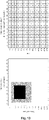
- Figures 6 to 15 show different grids for controlling the heat sources of the print head 42 (right graphic in each case in landscape format) and the resulting printed image on the direct thermal printing paper 34 (left graphic in each case in landscape format).
- the drawings of the print head 42 each show 14 heat sources 52 lying next to one another, which are controlled by the control device 48 independently of one another, regularly and as a function of the line time.
- a 1 means an active heat source, i.e. the heat source 52 has a current and temperature profile as shown in 3 is shown schematically.
- a 0 indicates an inactive heat source 52, that is, there is no heat output from this heat source.
- the printed image on the direct thermal printing paper 34 is shown schematically.
- a black area in the drawings indicates a black pixel.
- a hatched area in the drawings indicates a red pixel.
- a white area indicates an unprinted, i.e. white, area on the direct thermal printing paper 34.
- Regular grids are shown in each case, which have been selected from a larger area. It is therefore a zoom view of an area that appears to be the same color.
- a resolution of 300 dpi requires printing at around 12 dots/mm. That is, the in Figures 6 to 12
- the fields shown have a size of approximately 1.16 mm * 1.16 mm ( ⁇ 1.3 6 mm 2 ).
- FIG. 6 shows a raster with a high proportion of black dots. 75% of the heat sources are active. That is, only 25% of heat sources are inactive. A black color forms on the active heat sources, which is superimposed on the red color formed on the inactive heat sources. The area shown has a dark red tone due to the superimposition of the black and red colors. The human eye does not recognize the individual pixels, but only an area that forms this shade of red.
- Figures 7 to 12 each show areas that form different shades of red with different proportions of black pixels, red pixels and white pixels. In this case, individual heat sources in a row are activated by the control device.
- Figures 13 to 15 do not show square print areas, but are extended by one or two lines to complete the display. No regular grids have been singled out that extend beyond the edges of the illustrated drawings can be mentally extended. Rather, closed forms are shown.
- FIG. 13 shows a square black dot of 4x4 pixels (0.3 mm * 0.3 mm at 300 dpi).
- the direct thermal printing paper is moved quickly under the print head by the platen roller. This in 3
- the cooling interval ta shown is not large enough for the heat sources to have sufficiently cooled down at the point in time (6*tz, 7*tz ⁇ lines n+6, n+7). Therefore, the red color runs on a bit and after the black pixels have been printed in the transport direction, not only the pixels of the next line but also the pixels of the next but one line are colored red. The same effect occurs in 14 on.
- FIG. 14 shows a section of a barcode consisting of two bars that is printed in black.
- the black bars are of different lengths. It is therefore the lower left edge of a barcode.
- the bars at the edge of the barcode are slightly longer than in the middle, since the number corresponding to the barcode is printed in the middle of the barcode. Due to the reaction of the direct thermal printing paper, it is advantageous to position the bars of a barcode lengthwise in the transport direction. The red feathering effect on the printed paper is therefore at the end of the bars and not distributed across the barcode. This makes it easier to scan the barcode.
- the 15 shows schematically the printing of a number in black ink.
- the number contains very few pixels and would in reality be printed with significantly more black pixels. In reality, the proportion of red is negligible, so that the number printed in black is only surrounded by a very thin red border that is barely visible to the human eye.
- DSP digital signal processor
- ASIC application specific integrated circuit
- FPGA field programmable gate array
- ROM read only memory
- RAM random access memory
Landscapes
- Physics & Mathematics (AREA)
- Optics & Photonics (AREA)
- Electronic Switches (AREA)
Priority Applications (2)
| Application Number | Priority Date | Filing Date | Title |
|---|---|---|---|
| EP20218028.7A EP4023449B1 (fr) | 2020-12-31 | 2020-12-31 | Procédé de thermique directe multicolore et imprimante pour impression thermique directe multicolore |
| US17/548,619 US11731446B2 (en) | 2020-12-31 | 2021-12-13 | Method for multi-color direct thermal printing and printer for multi-color direct thermal printing |
Applications Claiming Priority (1)
| Application Number | Priority Date | Filing Date | Title |
|---|---|---|---|
| EP20218028.7A EP4023449B1 (fr) | 2020-12-31 | 2020-12-31 | Procédé de thermique directe multicolore et imprimante pour impression thermique directe multicolore |
Publications (2)
| Publication Number | Publication Date |
|---|---|
| EP4023449A1 true EP4023449A1 (fr) | 2022-07-06 |
| EP4023449B1 EP4023449B1 (fr) | 2024-11-27 |
Family
ID=74068236
Family Applications (1)
| Application Number | Title | Priority Date | Filing Date |
|---|---|---|---|
| EP20218028.7A Active EP4023449B1 (fr) | 2020-12-31 | 2020-12-31 | Procédé de thermique directe multicolore et imprimante pour impression thermique directe multicolore |
Country Status (2)
| Country | Link |
|---|---|
| US (1) | US11731446B2 (fr) |
| EP (1) | EP4023449B1 (fr) |
Families Citing this family (1)
| Publication number | Priority date | Publication date | Assignee | Title |
|---|---|---|---|---|
| CN116476537B (zh) * | 2023-04-21 | 2025-05-09 | 山东华菱电子股份有限公司 | 一种适于双色打印用热敏打印头的打印方法 |
Citations (8)
| Publication number | Priority date | Publication date | Assignee | Title |
|---|---|---|---|---|
| US5765954A (en) * | 1992-10-06 | 1998-06-16 | Seiko Epson Corporation | Tape printing device and tape cartridge used therein |
| EP1006000A1 (fr) * | 1998-11-30 | 2000-06-07 | Agfa-Gevaert N.V. | Procédé d'impression d'étiquette pour materiaux d'imagerie thermique directe comprenant un sel d'argent organique |
| DE60207488T2 (de) | 2001-06-14 | 2006-07-27 | Seiko Epson Corp. | Verfahren und Vorrichtung zur Steuerung eines Heizelementes in einem Thermokopf |
| DE60036515T2 (de) | 1999-07-21 | 2008-06-26 | Seiko Epson Corp. | Thermodrucker und Steuerungsverfahren dafür |
| ES2323736T3 (es) * | 2007-04-26 | 2009-07-23 | Skidata Ag | Procedimiento de impresion directa multicolor con una cabeza de impresion termica. |
| EP1866161B1 (fr) | 2005-04-06 | 2014-10-22 | Zink Imaging, Inc. | Procede d'imagerie thermique mutlicouleurs et imprimante thermique |
| EP3175993A1 (fr) | 2014-08-01 | 2017-06-07 | Seiko Epson Corporation | Support d'impression, unité de support d'impression et appareil d'impression |
| WO2020013820A1 (fr) * | 2018-07-11 | 2020-01-16 | Hewlett-Packard Development Company, L.P. | Espaces dans des résistances pour imagerie thermique |
Family Cites Families (1)
| Publication number | Priority date | Publication date | Assignee | Title |
|---|---|---|---|---|
| US7830405B2 (en) | 2005-06-23 | 2010-11-09 | Zink Imaging, Inc. | Print head pulsing techniques for multicolor printers |
-
2020
- 2020-12-31 EP EP20218028.7A patent/EP4023449B1/fr active Active
-
2021
- 2021-12-13 US US17/548,619 patent/US11731446B2/en active Active
Patent Citations (8)
| Publication number | Priority date | Publication date | Assignee | Title |
|---|---|---|---|---|
| US5765954A (en) * | 1992-10-06 | 1998-06-16 | Seiko Epson Corporation | Tape printing device and tape cartridge used therein |
| EP1006000A1 (fr) * | 1998-11-30 | 2000-06-07 | Agfa-Gevaert N.V. | Procédé d'impression d'étiquette pour materiaux d'imagerie thermique directe comprenant un sel d'argent organique |
| DE60036515T2 (de) | 1999-07-21 | 2008-06-26 | Seiko Epson Corp. | Thermodrucker und Steuerungsverfahren dafür |
| DE60207488T2 (de) | 2001-06-14 | 2006-07-27 | Seiko Epson Corp. | Verfahren und Vorrichtung zur Steuerung eines Heizelementes in einem Thermokopf |
| EP1866161B1 (fr) | 2005-04-06 | 2014-10-22 | Zink Imaging, Inc. | Procede d'imagerie thermique mutlicouleurs et imprimante thermique |
| ES2323736T3 (es) * | 2007-04-26 | 2009-07-23 | Skidata Ag | Procedimiento de impresion directa multicolor con una cabeza de impresion termica. |
| EP3175993A1 (fr) | 2014-08-01 | 2017-06-07 | Seiko Epson Corporation | Support d'impression, unité de support d'impression et appareil d'impression |
| WO2020013820A1 (fr) * | 2018-07-11 | 2020-01-16 | Hewlett-Packard Development Company, L.P. | Espaces dans des résistances pour imagerie thermique |
Also Published As
| Publication number | Publication date |
|---|---|
| EP4023449B1 (fr) | 2024-11-27 |
| US11731446B2 (en) | 2023-08-22 |
| US20220203742A1 (en) | 2022-06-30 |
Similar Documents
| Publication | Publication Date | Title |
|---|---|---|
| DE3529295C2 (fr) | ||
| DE69613938T2 (de) | Verwendung von Densitometer zur angepassten Steuerung der Wärmeabgabe eines Heizelementes, um die Trocknungszeit für unterschiedliche Druckmedien zu optimieren | |
| DE102005063486B3 (de) | Tintenstrahldruckvorrichtung | |
| DE69320584T2 (de) | Wärmeempfindliches Übertragungsdruckverfahren | |
| EP0331138B1 (fr) | Imprimante | |
| DE112016000361T5 (de) | Drucksystem und -verfahren | |
| DE2921120A1 (de) | Farbendrucker mit thermischer uebertragung | |
| DE69316984T2 (de) | Verfahren zur Bilderzeugung durch direkte thermische Aufzeichnung | |
| DE19909741B4 (de) | Bilderzeugungssystem | |
| DE69327430T2 (de) | System zum intensitätsvariablen Drucken | |
| DE68911676T2 (de) | Druckverfahren mit thermoschmelzender tinte. | |
| DE602005006076T2 (de) | Thermisches Drucken | |
| EP4023449B1 (fr) | Procédé de thermique directe multicolore et imprimante pour impression thermique directe multicolore | |
| DE2062494B2 (de) | Wärmedruckkopf | |
| EP1077129B1 (fr) | Procédé et dispositif pour la formation réversible d'images sur une forme d'impression | |
| EP4023448B1 (fr) | Procédé de génération des données de commande destiné à l'impression directe thermique multicolore | |
| DE2341181A1 (de) | Thermischer drucker | |
| DE60133358T2 (de) | Druckverfahren und für die Durchführung des Verfahrens geeigneter Drucker | |
| DE60207488T2 (de) | Verfahren und Vorrichtung zur Steuerung eines Heizelementes in einem Thermokopf | |
| DE69918480T2 (de) | Druckverfahren | |
| DE69424091T2 (de) | Drucker mit Thermodruckkopf | |
| DE4022974A1 (de) | Loeschbarer optischer aufzeichnungstraeger fuer farbige informationen | |
| EP0536526A2 (fr) | Méthode de commande de l'alimentation d'un élément chauffant d'une imprimante thermique | |
| DE69800517T2 (de) | Druckschwärzungskontrolle für thermisches Aufzeichnungsgerät | |
| DE19900475A1 (de) | Bilderzeugung mit Mikrokapseln |
Legal Events
| Date | Code | Title | Description |
|---|---|---|---|
| PUAI | Public reference made under article 153(3) epc to a published international application that has entered the european phase |
Free format text: ORIGINAL CODE: 0009012 |
|
| STAA | Information on the status of an ep patent application or granted ep patent |
Free format text: STATUS: THE APPLICATION HAS BEEN PUBLISHED |
|
| AK | Designated contracting states |
Kind code of ref document: A1 Designated state(s): AL AT BE BG CH CY CZ DE DK EE ES FI FR GB GR HR HU IE IS IT LI LT LU LV MC MK MT NL NO PL PT RO RS SE SI SK SM TR |
|
| STAA | Information on the status of an ep patent application or granted ep patent |
Free format text: STATUS: REQUEST FOR EXAMINATION WAS MADE |
|
| 17P | Request for examination filed |
Effective date: 20221117 |
|
| RBV | Designated contracting states (corrected) |
Designated state(s): AL AT BE BG CH CY CZ DE DK EE ES FI FR GB GR HR HU IE IS IT LI LT LU LV MC MK MT NL NO PL PT RO RS SE SI SK SM TR |
|
| GRAP | Despatch of communication of intention to grant a patent |
Free format text: ORIGINAL CODE: EPIDOSNIGR1 |
|
| STAA | Information on the status of an ep patent application or granted ep patent |
Free format text: STATUS: GRANT OF PATENT IS INTENDED |
|
| INTG | Intention to grant announced |
Effective date: 20240909 |
|
| GRAS | Grant fee paid |
Free format text: ORIGINAL CODE: EPIDOSNIGR3 |
|
| GRAA | (expected) grant |
Free format text: ORIGINAL CODE: 0009210 |
|
| STAA | Information on the status of an ep patent application or granted ep patent |
Free format text: STATUS: THE PATENT HAS BEEN GRANTED |
|
| AK | Designated contracting states |
Kind code of ref document: B1 Designated state(s): AL AT BE BG CH CY CZ DE DK EE ES FI FR GB GR HR HU IE IS IT LI LT LU LV MC MK MT NL NO PL PT RO RS SE SI SK SM TR |
|
| REG | Reference to a national code |
Ref country code: GB Ref legal event code: FG4D Free format text: NOT ENGLISH |
|
| REG | Reference to a national code |
Ref country code: CH Ref legal event code: EP |
|
| REG | Reference to a national code |
Ref country code: DE Ref legal event code: R096 Ref document number: 502020009829 Country of ref document: DE |
|
| REG | Reference to a national code |
Ref country code: IE Ref legal event code: FG4D Free format text: LANGUAGE OF EP DOCUMENT: GERMAN |
|
| REG | Reference to a national code |
Ref country code: LT Ref legal event code: MG9D |
|
| REG | Reference to a national code |
Ref country code: NL Ref legal event code: MP Effective date: 20241127 |
|
| PG25 | Lapsed in a contracting state [announced via postgrant information from national office to epo] |
Ref country code: HR Free format text: LAPSE BECAUSE OF FAILURE TO SUBMIT A TRANSLATION OF THE DESCRIPTION OR TO PAY THE FEE WITHIN THE PRESCRIBED TIME-LIMIT Effective date: 20241127 Ref country code: PT Free format text: LAPSE BECAUSE OF FAILURE TO SUBMIT A TRANSLATION OF THE DESCRIPTION OR TO PAY THE FEE WITHIN THE PRESCRIBED TIME-LIMIT Effective date: 20250327 Ref country code: IS Free format text: LAPSE BECAUSE OF FAILURE TO SUBMIT A TRANSLATION OF THE DESCRIPTION OR TO PAY THE FEE WITHIN THE PRESCRIBED TIME-LIMIT Effective date: 20250327 |
|
| PG25 | Lapsed in a contracting state [announced via postgrant information from national office to epo] |
Ref country code: FI Free format text: LAPSE BECAUSE OF FAILURE TO SUBMIT A TRANSLATION OF THE DESCRIPTION OR TO PAY THE FEE WITHIN THE PRESCRIBED TIME-LIMIT Effective date: 20241127 Ref country code: NL Free format text: LAPSE BECAUSE OF FAILURE TO SUBMIT A TRANSLATION OF THE DESCRIPTION OR TO PAY THE FEE WITHIN THE PRESCRIBED TIME-LIMIT Effective date: 20241127 |
|
| PG25 | Lapsed in a contracting state [announced via postgrant information from national office to epo] |
Ref country code: BG Free format text: LAPSE BECAUSE OF FAILURE TO SUBMIT A TRANSLATION OF THE DESCRIPTION OR TO PAY THE FEE WITHIN THE PRESCRIBED TIME-LIMIT Effective date: 20241127 |
|
| PG25 | Lapsed in a contracting state [announced via postgrant information from national office to epo] |
Ref country code: ES Free format text: LAPSE BECAUSE OF FAILURE TO SUBMIT A TRANSLATION OF THE DESCRIPTION OR TO PAY THE FEE WITHIN THE PRESCRIBED TIME-LIMIT Effective date: 20241127 |
|
| PG25 | Lapsed in a contracting state [announced via postgrant information from national office to epo] |
Ref country code: NO Free format text: LAPSE BECAUSE OF FAILURE TO SUBMIT A TRANSLATION OF THE DESCRIPTION OR TO PAY THE FEE WITHIN THE PRESCRIBED TIME-LIMIT Effective date: 20250227 |
|
| PG25 | Lapsed in a contracting state [announced via postgrant information from national office to epo] |
Ref country code: GR Free format text: LAPSE BECAUSE OF FAILURE TO SUBMIT A TRANSLATION OF THE DESCRIPTION OR TO PAY THE FEE WITHIN THE PRESCRIBED TIME-LIMIT Effective date: 20250228 Ref country code: LV Free format text: LAPSE BECAUSE OF FAILURE TO SUBMIT A TRANSLATION OF THE DESCRIPTION OR TO PAY THE FEE WITHIN THE PRESCRIBED TIME-LIMIT Effective date: 20241127 |
|
| PG25 | Lapsed in a contracting state [announced via postgrant information from national office to epo] |
Ref country code: PL Free format text: LAPSE BECAUSE OF FAILURE TO SUBMIT A TRANSLATION OF THE DESCRIPTION OR TO PAY THE FEE WITHIN THE PRESCRIBED TIME-LIMIT Effective date: 20241127 |
|
| PG25 | Lapsed in a contracting state [announced via postgrant information from national office to epo] |
Ref country code: RS Free format text: LAPSE BECAUSE OF FAILURE TO SUBMIT A TRANSLATION OF THE DESCRIPTION OR TO PAY THE FEE WITHIN THE PRESCRIBED TIME-LIMIT Effective date: 20250227 |
|
| PG25 | Lapsed in a contracting state [announced via postgrant information from national office to epo] |
Ref country code: SM Free format text: LAPSE BECAUSE OF FAILURE TO SUBMIT A TRANSLATION OF THE DESCRIPTION OR TO PAY THE FEE WITHIN THE PRESCRIBED TIME-LIMIT Effective date: 20241127 |
|
| PG25 | Lapsed in a contracting state [announced via postgrant information from national office to epo] |
Ref country code: DK Free format text: LAPSE BECAUSE OF FAILURE TO SUBMIT A TRANSLATION OF THE DESCRIPTION OR TO PAY THE FEE WITHIN THE PRESCRIBED TIME-LIMIT Effective date: 20241127 |
|
| PG25 | Lapsed in a contracting state [announced via postgrant information from national office to epo] |
Ref country code: EE Free format text: LAPSE BECAUSE OF FAILURE TO SUBMIT A TRANSLATION OF THE DESCRIPTION OR TO PAY THE FEE WITHIN THE PRESCRIBED TIME-LIMIT Effective date: 20241127 |
|
| PG25 | Lapsed in a contracting state [announced via postgrant information from national office to epo] |
Ref country code: RO Free format text: LAPSE BECAUSE OF FAILURE TO SUBMIT A TRANSLATION OF THE DESCRIPTION OR TO PAY THE FEE WITHIN THE PRESCRIBED TIME-LIMIT Effective date: 20241127 |
|
| PG25 | Lapsed in a contracting state [announced via postgrant information from national office to epo] |
Ref country code: SK Free format text: LAPSE BECAUSE OF FAILURE TO SUBMIT A TRANSLATION OF THE DESCRIPTION OR TO PAY THE FEE WITHIN THE PRESCRIBED TIME-LIMIT Effective date: 20241127 |
|
| PG25 | Lapsed in a contracting state [announced via postgrant information from national office to epo] |
Ref country code: CZ Free format text: LAPSE BECAUSE OF FAILURE TO SUBMIT A TRANSLATION OF THE DESCRIPTION OR TO PAY THE FEE WITHIN THE PRESCRIBED TIME-LIMIT Effective date: 20241127 |
|
| PG25 | Lapsed in a contracting state [announced via postgrant information from national office to epo] |
Ref country code: IT Free format text: LAPSE BECAUSE OF FAILURE TO SUBMIT A TRANSLATION OF THE DESCRIPTION OR TO PAY THE FEE WITHIN THE PRESCRIBED TIME-LIMIT Effective date: 20241127 |
|
| REG | Reference to a national code |
Ref country code: CH Ref legal event code: PL |
|
| PG25 | Lapsed in a contracting state [announced via postgrant information from national office to epo] |
Ref country code: LU Free format text: LAPSE BECAUSE OF NON-PAYMENT OF DUE FEES Effective date: 20241231 |
|
| REG | Reference to a national code |
Ref country code: DE Ref legal event code: R097 Ref document number: 502020009829 Country of ref document: DE |
|
| PG25 | Lapsed in a contracting state [announced via postgrant information from national office to epo] |
Ref country code: SE Free format text: LAPSE BECAUSE OF FAILURE TO SUBMIT A TRANSLATION OF THE DESCRIPTION OR TO PAY THE FEE WITHIN THE PRESCRIBED TIME-LIMIT Effective date: 20241127 |
|
| PG25 | Lapsed in a contracting state [announced via postgrant information from national office to epo] |
Ref country code: MC Free format text: LAPSE BECAUSE OF FAILURE TO SUBMIT A TRANSLATION OF THE DESCRIPTION OR TO PAY THE FEE WITHIN THE PRESCRIBED TIME-LIMIT Effective date: 20241127 |
|
| PLBE | No opposition filed within time limit |
Free format text: ORIGINAL CODE: 0009261 |
|
| STAA | Information on the status of an ep patent application or granted ep patent |
Free format text: STATUS: NO OPPOSITION FILED WITHIN TIME LIMIT |
|
| PG25 | Lapsed in a contracting state [announced via postgrant information from national office to epo] |
Ref country code: CH Free format text: LAPSE BECAUSE OF NON-PAYMENT OF DUE FEES Effective date: 20241231 |
|
| PG25 | Lapsed in a contracting state [announced via postgrant information from national office to epo] |
Ref country code: IE Free format text: LAPSE BECAUSE OF NON-PAYMENT OF DUE FEES Effective date: 20241231 |
|
| 26N | No opposition filed |
Effective date: 20250828 |
|
| PGFP | Annual fee paid to national office [announced via postgrant information from national office to epo] |
Ref country code: GB Payment date: 20251218 Year of fee payment: 6 |
|
| PGFP | Annual fee paid to national office [announced via postgrant information from national office to epo] |
Ref country code: AT Payment date: 20260113 Year of fee payment: 5 |
|
| PGFP | Annual fee paid to national office [announced via postgrant information from national office to epo] |
Ref country code: FR Payment date: 20251217 Year of fee payment: 6 |
|
| PGFP | Annual fee paid to national office [announced via postgrant information from national office to epo] |
Ref country code: BE Payment date: 20251223 Year of fee payment: 6 |
|
| PGFP | Annual fee paid to national office [announced via postgrant information from national office to epo] |
Ref country code: DE Payment date: 20251222 Year of fee payment: 6 |