EP4025874B1 - Dispositif de mesure d'angle de rotation, système de mesure d'angle de rotation et moteur électrique - Google Patents
Dispositif de mesure d'angle de rotation, système de mesure d'angle de rotation et moteur électrique Download PDFInfo
- Publication number
- EP4025874B1 EP4025874B1 EP19769724.6A EP19769724A EP4025874B1 EP 4025874 B1 EP4025874 B1 EP 4025874B1 EP 19769724 A EP19769724 A EP 19769724A EP 4025874 B1 EP4025874 B1 EP 4025874B1
- Authority
- EP
- European Patent Office
- Prior art keywords
- circuit board
- printed circuit
- rotation angle
- angle measuring
- board section
- Prior art date
- Legal status (The legal status is an assumption and is not a legal conclusion. Google has not performed a legal analysis and makes no representation as to the accuracy of the status listed.)
- Active
Links
Images
Classifications
-
- G—PHYSICS
- G01—MEASURING; TESTING
- G01D—MEASURING NOT SPECIALLY ADAPTED FOR A SPECIFIC VARIABLE; ARRANGEMENTS FOR MEASURING TWO OR MORE VARIABLES NOT COVERED IN A SINGLE OTHER SUBCLASS; TARIFF METERING APPARATUS; MEASURING OR TESTING NOT OTHERWISE PROVIDED FOR
- G01D11/00—Component parts of measuring arrangements not specially adapted for a specific variable
- G01D11/24—Housings ; Casings for instruments
- G01D11/245—Housings for sensors
-
- G—PHYSICS
- G01—MEASURING; TESTING
- G01D—MEASURING NOT SPECIALLY ADAPTED FOR A SPECIFIC VARIABLE; ARRANGEMENTS FOR MEASURING TWO OR MORE VARIABLES NOT COVERED IN A SINGLE OTHER SUBCLASS; TARIFF METERING APPARATUS; MEASURING OR TESTING NOT OTHERWISE PROVIDED FOR
- G01D5/00—Mechanical means for transferring the output of a sensing member; Means for converting the output of a sensing member to another variable where the form or nature of the sensing member does not constrain the means for converting; Transducers not specially adapted for a specific variable
- G01D5/12—Mechanical means for transferring the output of a sensing member; Means for converting the output of a sensing member to another variable where the form or nature of the sensing member does not constrain the means for converting; Transducers not specially adapted for a specific variable using electric or magnetic means
- G01D5/14—Mechanical means for transferring the output of a sensing member; Means for converting the output of a sensing member to another variable where the form or nature of the sensing member does not constrain the means for converting; Transducers not specially adapted for a specific variable using electric or magnetic means influencing the magnitude of a current or voltage
- G01D5/142—Mechanical means for transferring the output of a sensing member; Means for converting the output of a sensing member to another variable where the form or nature of the sensing member does not constrain the means for converting; Transducers not specially adapted for a specific variable using electric or magnetic means influencing the magnitude of a current or voltage using Hall-effect devices
- G01D5/145—Mechanical means for transferring the output of a sensing member; Means for converting the output of a sensing member to another variable where the form or nature of the sensing member does not constrain the means for converting; Transducers not specially adapted for a specific variable using electric or magnetic means influencing the magnitude of a current or voltage using Hall-effect devices influenced by the relative movement between the Hall device and magnetic fields
-
- G—PHYSICS
- G01—MEASURING; TESTING
- G01D—MEASURING NOT SPECIALLY ADAPTED FOR A SPECIFIC VARIABLE; ARRANGEMENTS FOR MEASURING TWO OR MORE VARIABLES NOT COVERED IN A SINGLE OTHER SUBCLASS; TARIFF METERING APPARATUS; MEASURING OR TESTING NOT OTHERWISE PROVIDED FOR
- G01D5/00—Mechanical means for transferring the output of a sensing member; Means for converting the output of a sensing member to another variable where the form or nature of the sensing member does not constrain the means for converting; Transducers not specially adapted for a specific variable
- G01D5/12—Mechanical means for transferring the output of a sensing member; Means for converting the output of a sensing member to another variable where the form or nature of the sensing member does not constrain the means for converting; Transducers not specially adapted for a specific variable using electric or magnetic means
- G01D5/14—Mechanical means for transferring the output of a sensing member; Means for converting the output of a sensing member to another variable where the form or nature of the sensing member does not constrain the means for converting; Transducers not specially adapted for a specific variable using electric or magnetic means influencing the magnitude of a current or voltage
Definitions
- the invention relates to a rotation angle measuring arrangement with a rotatable shaft and a rotation angle measuring system for detecting a shaft rotational movement, the rotation angle measuring system comprising: an excitation unit which is non-rotatably connected to the shaft and has at least one permanent magnetic excitation magnet, a circuit board arrangement with a first circuit board section which is perpendicular to a shaft longitudinal axis, and a second circuit board section, which is arranged at an angle to the first circuit board section and is electrically connected to the first circuit board section via a connecting device, a first magnetic field sensor, which is arranged on the first circuit board section and through which one of the excitation unit generated excitation magnetic field can be detected, an evaluation electronics which is arranged on the circuit board arrangement and which is electrically connected to the first magnetic field sensor.
- Such rotation angle measuring arrangements are used to detect rotational movements of a shaft, with rotation angle measuring systems often also being referred to as angle measuring devices, rotation angle sensors or rotary encoders. Such rotation angle measuring arrangements are used in particular for controlling and monitoring electric motors, in particular servo motors, in machines, systems or vehicles. The installation space available for the rotation angle measuring system is often limited.
- the circuit board arrangement includes a first circuit board section and a second circuit board section, which is arranged at an angle to the first circuit board section and is electrically connected to the first circuit board section.
- the second circuit board section is arranged such that a parallel projection of the second circuit board section onto a longitudinal plane and a parallel projection of an excitation unit onto this longitudinal plane at least partially overlap.
- a rotation angle measuring arrangement with a rotation angle measuring system which has a circuit board arrangement with a first circuit board section which is arranged perpendicular to a shaft longitudinal axis, a second circuit board section which is arranged at an angle to the first circuit board section, and a third circuit board section which is flexible and the first circuit board section electrically connects to the second circuit board section, known.
- the rotation angle measuring arrangement disclosed has a relatively small radial extent due to the angled arrangement of the circuit board sections, but has a relatively large axial extent. Often, however, not only the radial installation space available for the rotation angle measuring system, but also the axial installation space available is limited.
- the task is therefore to create a rotation angle measuring arrangement with a relatively compact rotation angle measuring system.
- This task is achieved by a rotation angle measuring arrangement with the features of claim 1. Furthermore, this task is carried out by a Rotation angle measuring system with the features of claim 14 and solved by an electric motor with the features of claim 15.
- the radial and axial directions always refer to the - potential - orientation of the shaft to be detected by the rotation angle measuring system.
- the second circuit board section is arranged such that a parallel projection of the second circuit board section onto a longitudinal plane parallel to the shaft longitudinal axis and a projection of the excitation unit onto this longitudinal plane at least partially overlap.
- the longitudinal plane can be any plane that is parallel to the shaft's longitudinal axis, i.e. any plane whose surface normal is perpendicular to the shaft's longitudinal axis.
- the second circuit board section is therefore at least partially arranged radially adjacent to the exciter unit.
- an end of the second circuit board section facing away from the first circuit board section does not protrude in the axial direction beyond an axial end of the exciter unit facing away from the first circuit board section.
- the second circuit board section protrudes axially beyond the axial end of the excitation unit facing away from the first circuit board section; preferably, the axial projection of the second circuit board section over the axial end of the excitation unit facing away from the first circuit board section is a maximum of 10% of the axial extent of the second circuit board section.
- the second circuit board section Due to the angled arrangement of the second circuit board section, only a relatively small radial installation space on the shaft is required for the rotation angle measuring system according to the invention. Because of that the second circuit board section is at least partially arranged radially adjacent to the exciter unit and preferably protrudes only slightly axially beyond it, only a relatively small axial installation space is required for the rotation angle measuring system according to the invention. This consequently creates a rotation angle measuring arrangement with a relatively compact rotation angle measuring system.
- the rotation angle measuring system has a second magnetic field sensor, through which the exciter magnetic field generated by the exciter unit can be detected.
- the second magnetic field sensor enables a particularly precise and reliable detection of the exciter magnetic field and thus creates a particularly reliable rotation angle measuring system.
- one magnetic field sensor is a so-called Wiegand sensor and the other magnetic field sensor is a so-called Hall sensor.
- the first magnetic field sensor and the second magnetic field sensor are arranged on opposite sides of the first circuit board section, with both magnetic field sensors preferably being positioned substantially concentrically to the shaft. This creates a reliable and compact rotation angle measuring system.
- the angle between the first circuit board section and the second circuit board section is in an angular range of 70° to 110°, particularly preferably in an angular range of 80° to 100°. This creates a circuit board arrangement with a particularly small radial expansion and thus a particularly compact rotation angle measuring system.
- the second circuit board section is arranged such that a parallel projection of the second circuit board section is on a transverse plane perpendicular to the longitudinal axis of the shaft and a parallel projection of the first Circuit board section at least partially overlap this transverse plane.
- the transverse plane can be any plane that extends transversely to the shaft's longitudinal axis, i.e. any plane whose surface normal is parallel to the shaft's longitudinal axis.
- the second circuit board section is therefore arranged axially adjacent to the first circuit board section.
- the second circuit board section is arranged such that at least 90% of the transverse plane projection area of the second circuit board section is within the transverse plane projection area of the first circuit board section.
- the second circuit board section is arranged such that the transverse plane projection surface of the second circuit board section is located completely within the transverse plane projection surface of the first circuit board section. This creates a circuit board arrangement with a particularly small radial expansion and thus a particularly compact rotation angle measuring system.
- the connecting device is formed by a flexible third circuit board section.
- the connecting device is particularly preferably formed by a so-called “rigid-flex” printed circuit board.
- the third circuit board section has conductor tracks that extend from the first circuit board section through the third circuit board section into the second circuit board section. This creates a particularly reliable electrical connection between the first and second circuit board sections, which does not require soldering points and/or connecting plugs.
- the flexible third circuit board section enables particularly complex electrical circuits to be easily implemented.
- the evaluation electronics advantageously have at least one electronic component, which is located between the first circuit board section and the magnetic field sensor is arranged.
- the at least one electronic component is therefore arranged “below” the magnetic field sensor, so that the at least one electronic component does not take up any additional space on the circuit board arrangement.
- several electronic components of the evaluation electronics are arranged between the second circuit board section and the magnetic field sensor. This reduces the required circuit board area, making it possible to realize a particularly compact circuit board arrangement and thus a particularly compact rotation angle measuring system.
- the rotation angle measuring system has a circuit board support element which supports the first circuit board section on a first axial side and has a first snap device via which the second circuit board section is positively fastened to the circuit board support element.
- the circuit board support element preferably also has a positioning device through which the first circuit board section is positioned and fixed radially and rotationally.
- the circuit board support element is essentially cylindrical and encloses the exciter unit at least partially radially, with a recess being provided in the circuit board support element, in which the second circuit board section can be fastened via the snap device.
- the circuit board arrangement with the first circuit board section is placed axially on the circuit board carrier and the second circuit board section is easily inserted into the snap device. This enables easy assembly of the angle of rotation measuring system, with the entire circuit board arrangement - in particular the second circuit board section arranged at an angle - being reliably attached and aligned.
- the rotation angle measuring system advantageously has a circuit board fixing element which is attached to the circuit board support element and supports the first circuit board section on a second axial side opposite the first axial side.
- the circuit board fixing element is attached to the circuit board support element via a screw connection.
- the circuit board fixing element creates a simple and reliable fixation of the circuit board arrangement.
- the circuit board fixing element is essentially pot-shaped and essentially completely encloses the first magnetic field sensor, particularly preferably both magnetic field sensors, on the radial outside.
- a recess is preferably provided in a radial bottom region of the circuit board fixing element, into which an axial end of the magnetic field sensor facing away from the first circuit board section is immersed.
- the circuit board fixing element thus also creates mechanical protection for the sensitive magnetic field sensor.
- the rotation angle measuring system has a pot-shaped magnetizable shielding element, with the first magnetic field sensor, particularly preferably both magnetic field sensors, and the first circuit board section being arranged completely within the shielding element.
- the shielding element generally consists of a soft magnetic metal and shields the magnetic field sensor(s) from external magnetic fields that may affect the reliability and/or accuracy of the detection of the shaft speed by the magnetic field sensor(s).
- the shielding element typically also forms a housing part of the rotation angle measuring system. The shielding element therefore creates a reliable and compact rotation angle measuring system.
- the relatively sensitive evaluation electronics are particularly preferably arranged completely within the shielding element and are therefore also shielded from external magnetic fields. This creates a particularly reliable rotation angle measuring system.
- a second snap device is formed on the circuit board support element and/or on the circuit board fixing element, through which the shielding element is fixed axially and rotationally.
- the snap device is preferably formed on a radial outside of the circuit board support element and/or the circuit board fixing element, with the shielding element having at least one recess in a cylinder wall into which the snap device engages.
- the snap device provides reliable alignment and fastening of the shielding element, and the shielding element can also be mounted in a simple manner.
- the rotation angle measuring system preferably has a magnetizable shielding disk which radially surrounds the shaft.
- the shielding disk generally consists of a soft magnetic metal and shields the magnetic field sensor, particularly preferably both magnetic field sensors, as well as evaluation electronics from external magnetic fields, in particular from magnetic fields that are generated in a stator and / or rotor of an electric motor driving the shaft. This creates a particularly reliable rotation angle measuring system.
- the shielding disk preferably also forms an adapter element, via which the rotation angle measuring system can be easily attached to a predefined measuring system receiving device, for example on a motor flange.
- the angle of rotation measuring system has a connector for external power supply and/or for reading/programming the angle of rotation measuring system, which is arranged on the circuit board arrangement and is electrically connected to the evaluation electronics.
- the connector protrudes essentially vertically from the circuit board arrangement.
- the connecting plug is advantageously arranged on a radial outside of the second circuit board section. For the connecting plug and for a connecting plug that can be connected to the connecting plug, only one radial installation space and no additional axial installation space must be provided. This creates a particularly compact rotation angle measuring arrangement.
- the connecting plug is arranged outside the radial and axial expansion range of the first magnetic field sensor, particularly preferably outside the radial and axial expansion range of both magnetic field sensors, so that no recess for the connecting plug in the shielding element has to be provided within the expansion range of the magnetic field sensor(s). This creates a particularly reliable shield for the magnetic field sensor(s) and thus a particularly reliable rotation angle measuring system.
- the technical task is further solved by a rotation angle measuring system with the features described above.
- the radial and axial directions refer to the potential shaft orientation that the shaft assumes within a rotation angle measuring system mounted on the shaft.
- an electric motor with a rotation angle measuring arrangement with the features described above, the circuit board support element being attached to a motor flange.
- the circuit board support element can be attached directly to the motor flange or can, preferably, be attached to the motor flange via an adapter plate.
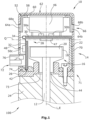
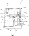
- Figure 1 shows an electric motor 100 with a rotation angle measuring arrangement 10 for detecting a rotational movement of a driven shaft 12 of the electric motor 100.
- the rotation angle measuring arrangement 10 comprises the shaft 12 and a rotation angle measuring system 14 arranged on the shaft 12.
- the angle of rotation measuring system 14 comprises an excitation unit 16 with a magnet holder 18, which is connected to the shaft 12 in a rotationally fixed manner, and a permanent magnetic excitation magnet 20, which is fastened in the magnet holder 18 and is therefore connected to the shaft 12 in a rotationally fixed manner.
- the angle of rotation measuring system 14 further comprises a substantially cylindrical circuit board support element 22, which is attached to a motor flange 24 via a screw connection, axially between the circuit board support element 22 and the motor flange 24 a soft magnetic metallic shielding disk 26 is arranged.
- the shielding disk 26 surrounds the shaft 12 radially and, in the present exemplary embodiment, also forms an adapter element for simple and reliable attachment of the rotation angle measuring system 14 to the motor flange 24.
- the rotation angle measuring system 14 further comprises a circuit board arrangement 28 with three circuit board sections 30,32,34.
- the first circuit board section 30 is essentially circular segment-shaped and is arranged perpendicular to a shaft longitudinal axis L of the shaft 12.
- the first circuit board section 30 is supported by the circuit board support element 22 on a first axial side 31 facing the excitation unit 16.
- the second circuit board section 32 is essentially rectangular in shape and is arranged in a recess 36 formed within the circuit board support element 22, the second circuit board section 32 being positively fastened to the circuit board support element 22 by a first snap device 40 formed by two snap hooks 38.
- the second circuit board section 32 is arranged such that a parallel projection of the second circuit board section 32 onto a transverse plane Q of the rotation angle measuring arrangement 10 and a parallel projection of the first circuit board section 30 onto the transverse plane Q of the rotation angle measuring arrangement 10 almost completely overlap.
- the second circuit board section 32 is arranged at an angle of 90° to the first circuit board section 30 and radially adjacent to the excitation unit 16.
- the second circuit board section 32 is arranged such that a parallel projection of the second circuit board section 32 is parallel to the shaft longitudinal axis L and includes the shaft longitudinal axis L Longitudinal plane E and a parallel projection of the exciter unit 16 onto the longitudinal plane E overlap.
- the second circuit board section 32 is further arranged such that an end 42 of the second circuit board section 32 facing away from the first circuit board section 30 does not protrude axially beyond an end 44 of the excitation unit 16 facing away from the first circuit board section 30.
- the second circuit board section 32 is electrically connected to the first circuit board section 30 via a connecting device 34.
- the connecting device 34 is formed by a third circuit board section, which is flexible and includes conductor tracks (not shown in more detail).
- the connecting device 34 is preferably formed by a so-called “rigid-flex” printed circuit board.
- the rotation angle measuring system 14 further comprises a first magnetic field sensor 46, which is a so-called Wiegand sensor in the present exemplary embodiment, and a second magnetic field sensor 47, which is a so-called Hall sensor in the present exemplary embodiment.
- Both magnetic field sensors 46, 47 are arranged axially adjacent to the excitation unit 16 and essentially concentric to the shaft 12 and to the excitation magnet 20 on the first circuit board section 30 , so that an exciter magnetic field generated by the exciter unit 16 can be detected by both magnetic field sensors 46,47.
- the first magnetic field sensor 46 and the second magnetic field sensor 47 are arranged on opposite axial sides of the first circuit board section 30.
- the rotation angle measuring system 14 further includes evaluation electronics 48 which is formed by several electronic components 50a-50c which are on the Circuit board arrangement 28 are arranged.
- the evaluation electronics 48 is electrically connected to the two magnetic field sensors 46,47 in order to evaluate sensor signals generated by the magnetic field sensors 46,47.
- several electronic components 50a, 50b of the evaluation electronics 48 are arranged below the first magnetic field sensor 46, i.e. in the axial direction between the first circuit board section 30 and the first magnetic field sensor 46.
- the rotation angle measuring system 14 further comprises a substantially pot-shaped circuit board fixing element 52, which is attached to the circuit board support element 22 via a screw connection and axially supports the first circuit board section 30 on a second axial side 54 opposite the first axial side 31.
- the first circuit board section 30 is consequently axially fixed by the circuit board fixing element 52 and the circuit board support element 22.
- the screw connection extends axially through a hole, not shown, in the first circuit board section 30, so that the first circuit board section 30 is fixed radially and rotationally by the screw connection.
- a cylinder wall 56 of the circuit board fixing element 52 completely encloses the two magnetic field sensors 46, 47 on a radial outside and a bottom wall 58 of the circuit board fixing element 52 has a recess 60 into which the first magnetic field sensor 46 is immersed.
- the rotation angle measuring system 14 further comprises a substantially pot-shaped soft magnetic metallic shielding element 62.
- the shielding element 62 is connected via a second snap device 66 formed by a plurality of snap elements 64a, 64b, which engages in corresponding recesses 68a, 68b in a cylinder wall 70 of the shielding element 62 attached to the circuit board fixing element 52 and fixed axially and rotationally.
- the shielding element 62 forms the present one Embodiment example is a housing part of the rotation angle measuring system 14. Both magnetic field sensors 46, 47 and the first circuit board section 30 are arranged completely within the shielding element 62 and are therefore reliably shielded from external magnetic fields by the shielding element 62.
- the shielding element 62 rests axially on the shielding disk 26 and, together with the shielding disk 26, forms a shielding arrangement 71, which covers both magnetic field sensors 46, 47 and the entire evaluation electronics 48 essentially completely in all spatial directions - that is, with the exception of the recesses 76 for the Connecting plug 72, which extends through the shaft 12 - recesses 78a, b for the second snap device and a recess 73 - and thus effectively shields against external magnetic fields.
- the angle of rotation measuring system 14 further includes a connecting plug 72 for external energy supply and for reading/programming the angle of rotation measuring system 14.
- the connecting plug 72 is arranged on a radial outside 74 of the second circuit board section 32 and is electrically connected to the evaluation electronics 48.
- the cylinder wall 70 of the shielding element 62 has a recess 76 through which the connecting plug 72 extends.
Landscapes
- Physics & Mathematics (AREA)
- General Physics & Mathematics (AREA)
- Transmission And Conversion Of Sensor Element Output (AREA)
Claims (13)
- assemblage de mesure de l'angle de rotation (10) avecun arbre rotatif (12) etun système de détection d'angle de rotation (14) pour détecter un mouvement de rotation de l'arbre, le système de détection d'angle de rotation (14) comprenant :caractérisé en ce que- une unité d'excitation (16) qui est reliée à l'arbre (12) sans pouvoir tourner et qui comprend au moins un aimant d'excitation à aimant permanent (20),- un ensemble de circuit imprimé (28) avec-- une première section de carte de circuit imprimé (30), qui est disposée perpendiculairement à un axe longitudinal (L) de l'arbre, et-- une deuxième partie de carte de circuit imprimé (32) disposée en angle relativement à la première section de carte de circuit imprimé (30) et connectée électriquement avec la première section de carte de circuit imprimé (30) par un moyen de connexion (34),
la deuxième section de carte de circuit imprimé (32) étant disposée de telle sorte qu'une projection parallèle de la deuxième section de carte de circuit imprimé (32) sur un plan longitudinal (E) parallèle à l'axe longitudinal (L) de l'arbre et une projection parallèle de l'unité d'excitation (16) sur ce plan longitudinal (E) se couvrent au moins partiellement,- un premier capteur de champ magnétique (46), qui est disposé sur la première section de circuit imprimé (30) et par lequel un champ magnétique d'excitation généré par l'unité d'excitation (16) peut être détecté, et- une électronique d'évaluation (48) qui est disposée sur l'ensemble de cartes de circuits imprimés (28) et qui est reliée électriquement au capteur de champ magnétique (46),
le système de détection d'angle de rotation (14) comprend un deuxième capteur de champ magnétique (47) par lequel le champ magnétique d'excitation généré par l'unité d'excitation (16) peut être détecté, de préférence le premier capteur de champ magnétique (46) et le deuxième capteur de champ magnétique (47) sont disposés sur des côtés opposés du premier section de carte de circuit imprimé (30). - assemblage de mesure de l'angle de rotation (10) selon la revendication 1, dans lequel l'angle entre la première section de carte de circuit imprimé (30) et la deuxième section de carte de circuit imprimé (32) est dans un intervalle angulaire de 70° à 110°, de préférence dans un intervalle angulaire de 80° à 100°.
- assemblage de mesure de l'angle de rotation (10) selon l'une des revendications précédentes, dans lequel la deuxième section de circuit imprimé (32) est disposée de telle sorte qu'une projection parallèle de la deuxième section de circuit imprimé (32) sur un plan transversal (Q) perpendiculaire à l'axe longitudinal (L) de l'arbre et une projection parallèle de la première section de circuit imprimé (30) sur ce plan transversal (Q) se couvrent au moins partiellement.
- assemblage de mesure de l'angle de rotation (10) selon l'une des revendications précédentes, dans lequel le moyen de connexion (34) est formé par une troisième section de circuit imprimé flexible.
- assemblage de mesure de l'angle de rotation (10) selon l'une des revendications précédentes, dans lequel le circuit électronique d'évaluation (48) comprend au moins un composant électronique (50a, 50b) disposé entre la première section de circuit imprimé (30) et le capteur de champ magnétique (46).
- assemblage de mesure de l'angle de rotation (10) selon l'une des revendications précédentes, dans lequel le système de mesure de l'angle de rotation (14) comprend un élément de support de circuit imprimé (22) qui supporte la première section de circuit imprimé (30) sur un premier côté axial (31) et comprend un premier dispositif d'encliquetage (40) par lequel la deuxième section de circuit imprimé (32) est fixée par coopération de formes à l'élément de support de circuit imprimé (22).
- assemblage de mesure de l'angle de rotation (10) selon la revendication 6, dans lequel le système de détection de l'angle de rotation (14) comprend un élément de fixation de la carte de circuit imprimé (52) qui est fixé à l'élément de support de carte de circuit imprimé (22) et qui supporte la première section de la carte de circuit imprimé (30) sur un deuxième côté axial (54) opposé au premier côté axial (31).
- assemblage de mesure de l'angle de rotation (10) selon l'une des revendications précédentes, dans lequel le système de détection de l'angle de rotation (14) comprend un élément de shield (62) magnétisable en forme de pot, et dans lequel le capteur de champ magnétique (46) et la première section de circuit imprimé (30) sont entièrement disposés à l'intérieur de l'élément de shield (62).
- assemblage de mesure de l'angle de rotation (10) selon la revendication 8, dans lequel l'électronique d'évaluation (48) est disposée entièrement à l'intérieur de l'élément de shield (62).
- assemblage de mesure de l'angle de rotation (10) selon l'une des revendications 6 ou 7 et la revendication 8 ou 9, dans lequel un deuxième dispositif d'encliquetage (66) est formé sur l'élément de support de carte de circuit imprimé (22) et/ou sur l'élément de fixation de carte de circuit imprimé (52), par lequel l'élément de shield (62) est fixé axialement et en rotation.
- assemblage de mesure de l'angle de rotation (10) selon l'une des revendications précédentes, dans lequel le système de détection de l'angle de rotation (14) comprend un disque de blindage magnétisable (26) qui entoure radialement l'arbre (12).
- assemblage de mesure de l'angle de rotation (10) selon l'une des revendications précédentes, dans lequel le système de détection de l'angle de rotation (14) comprend une fiche de connexion (72) qui est reliée électriquement à l'électronique de valorisation (48), et dans lequel la fiche de connexion (72) est disposée sur une face radiale extérieure (74) de la deuxième section de circuit imprimé (32).
- moteur électrique (100) comprenant un assemblage de mesure de l'angle de rotation (10) selon l'une des revendications 7 à 12, dans lequel l'arbre (12) est entraîné par le moteur électrique (100), et dans lequel l'élément de support de carte de circuit imprimé (22) est fixé à une bride de moteur (24).
Applications Claiming Priority (1)
| Application Number | Priority Date | Filing Date | Title |
|---|---|---|---|
| PCT/EP2019/073736 WO2021043409A1 (fr) | 2019-09-05 | 2019-09-05 | Dispositif de mesure d'angle de rotation, système de mesure d'angle de rotation et moteur électrique |
Publications (2)
| Publication Number | Publication Date |
|---|---|
| EP4025874A1 EP4025874A1 (fr) | 2022-07-13 |
| EP4025874B1 true EP4025874B1 (fr) | 2023-11-01 |
Family
ID=67988957
Family Applications (1)
| Application Number | Title | Priority Date | Filing Date |
|---|---|---|---|
| EP19769724.6A Active EP4025874B1 (fr) | 2019-09-05 | 2019-09-05 | Dispositif de mesure d'angle de rotation, système de mesure d'angle de rotation et moteur électrique |
Country Status (5)
| Country | Link |
|---|---|
| US (1) | US12111183B2 (fr) |
| EP (1) | EP4025874B1 (fr) |
| JP (1) | JP7462030B2 (fr) |
| CN (1) | CN114270144B (fr) |
| WO (1) | WO2021043409A1 (fr) |
Cited By (1)
| Publication number | Priority date | Publication date | Assignee | Title |
|---|---|---|---|---|
| EP4647728A1 (fr) * | 2024-05-07 | 2025-11-12 | Hella Gmbh & Co. Kgaa | Dispositif de capteur d'angle de rotation et système modulaire pour la fabrication d'un dispositif de capteur d'angle de rotation |
Families Citing this family (3)
| Publication number | Priority date | Publication date | Assignee | Title |
|---|---|---|---|---|
| CN116917697A (zh) * | 2021-02-26 | 2023-10-20 | 美蓓亚三美株式会社 | 磁检测装置以及绝对编码器 |
| DE102021120971A1 (de) * | 2021-08-11 | 2023-02-16 | Endress+Hauser Flowtec Ag | Transmittergehäuse eines Feldgeräts |
| GB2642873A (en) * | 2024-07-23 | 2026-01-28 | Zf Automotive Uk Ltd | Magnetic encoder assembly |
Family Cites Families (29)
| Publication number | Priority date | Publication date | Assignee | Title |
|---|---|---|---|---|
| JPH0849575A (ja) | 1994-08-08 | 1996-02-20 | Nippondenso Co Ltd | アクセルペダルの操作量検出装置 |
| JP2947340B2 (ja) * | 1997-05-19 | 1999-09-13 | 日本電気株式会社 | 磁界センサ及びこれを利用した磁界測定装置 |
| JP3595149B2 (ja) | 1998-01-26 | 2004-12-02 | 株式会社ミツバ | 回転検知装置付きの電動モータ |
| CA2293857A1 (fr) * | 2000-01-04 | 2001-07-04 | Hui Li | Capteur pouvant deceler la position angulaire absolue d'un objet cylindrique |
| JP2003294409A (ja) | 2002-03-28 | 2003-10-15 | Bosch Automotive Systems Corp | 舵角センサ、該舵角センサを搭載した舵角センサ組み込み式回転コネクタ装置 |
| DE102004047991A1 (de) | 2003-10-02 | 2005-06-23 | Aisan Kogyo K.K., Obu | Rotationswinkelsensoren |
| DE10360042A1 (de) * | 2003-12-18 | 2005-07-21 | Valeo Motoren Und Aktuatoren Gmbh | Verfahren und Meßsystem zur Bestimmung einer absoluten Winkellage |
| DE102007018758B4 (de) | 2007-01-08 | 2019-05-29 | Asm Automation Sensorik Messtechnik Gmbh | Winkelsensor |
| DE102007039051B8 (de) * | 2007-08-17 | 2023-09-28 | Avago Technologies International Sales Pte. Limited | Absoluter feinauflösender Segment- oder Umdrehungszähler |
| JP5148418B2 (ja) | 2008-09-05 | 2013-02-20 | 日本電産サンキョー株式会社 | 磁気式回転検出装置 |
| DE102009048389B4 (de) * | 2009-10-06 | 2019-12-19 | Asm Automation Sensorik Messtechnik Gmbh | Anordnung zur Erfassung mehr als einer Umdrehung mitels Magneten als Positionsgeber |
| JP2012002519A (ja) | 2010-06-14 | 2012-01-05 | Panasonic Corp | 回転角度・トルク検出装置 |
| DE102010033769A1 (de) * | 2010-08-09 | 2012-02-09 | Valeo Schalter Und Sensoren Gmbh | Vorrichtung mit einem Drehmomentsensor und einem Drehwinkelsensor |
| US9000763B2 (en) * | 2011-02-28 | 2015-04-07 | Infineon Technologies Ag | 3-D magnetic sensor |
| CN202216701U (zh) * | 2011-07-11 | 2012-05-09 | 联创汽车电子有限公司 | 巨磁阻效应节气门角度位置传感器 |
| JP5861660B2 (ja) * | 2013-04-23 | 2016-02-16 | 株式会社デンソー | 回転電機 |
| US9803997B2 (en) * | 2013-07-26 | 2017-10-31 | Bei Sensors & Systems Company, Inc. | System and method for determining absolute angular position of a rotating member |
| CN203422059U (zh) * | 2013-07-31 | 2014-02-05 | 廖启新 | 一种线性永磁角度测量装置 |
| JP6281688B2 (ja) | 2014-02-04 | 2018-02-21 | 日立オートモティブシステムズ株式会社 | モータ制御装置およびパワーステアリング装置 |
| DE102014205386A1 (de) | 2014-03-24 | 2015-09-24 | Robert Bosch Gmbh | Elektronikmodul, insbesondere für Getriebesteuergerät, mit integriertem elektronischem Sensorelement |
| JP6402491B2 (ja) * | 2014-05-21 | 2018-10-10 | 株式会社テージーケー | モータアクチュエータ |
| JP6373079B2 (ja) | 2014-06-13 | 2018-08-15 | 日本電産サンキョー株式会社 | センサ装置およびエンコーダ |
| JP6361377B2 (ja) | 2014-08-27 | 2018-07-25 | 日本精工株式会社 | センサ |
| US20160254732A1 (en) * | 2015-02-27 | 2016-09-01 | Jtekt Corporation | Motor unit |
| JP2016192832A (ja) | 2015-03-30 | 2016-11-10 | 日本電産株式会社 | モータ |
| JP6418063B2 (ja) | 2015-05-20 | 2018-11-07 | 株式会社デンソー | センサ装置、これを用いた電動パワーステアリング装置、および、制御装置 |
| JP6848306B2 (ja) | 2016-09-29 | 2021-03-24 | 株式会社ニコン | エンコーダ装置、駆動装置、ステージ装置、ロボット装置、及びエンコーダ装置の取り付け方法 |
| WO2018219454A1 (fr) | 2017-05-31 | 2018-12-06 | Fraba B.V. | Unité à capteur pour système de mesure d'angle de rotation et système de mesure d'angle de rotation équipé d'une telle unité de détection |
| EP3415871A1 (fr) * | 2017-06-12 | 2018-12-19 | Fraba B.V. | Système de capteur destiné à détecter des lignes d'un champ magnétique ou d'un système de détection ou d'un système de mesure d'angle de rotation |
-
2019
- 2019-09-05 US US17/639,911 patent/US12111183B2/en active Active
- 2019-09-05 EP EP19769724.6A patent/EP4025874B1/fr active Active
- 2019-09-05 JP JP2022514143A patent/JP7462030B2/ja active Active
- 2019-09-05 CN CN201980099640.3A patent/CN114270144B/zh active Active
- 2019-09-05 WO PCT/EP2019/073736 patent/WO2021043409A1/fr not_active Ceased
Cited By (1)
| Publication number | Priority date | Publication date | Assignee | Title |
|---|---|---|---|---|
| EP4647728A1 (fr) * | 2024-05-07 | 2025-11-12 | Hella Gmbh & Co. Kgaa | Dispositif de capteur d'angle de rotation et système modulaire pour la fabrication d'un dispositif de capteur d'angle de rotation |
Also Published As
| Publication number | Publication date |
|---|---|
| US20220333959A1 (en) | 2022-10-20 |
| JP2022547020A (ja) | 2022-11-10 |
| US12111183B2 (en) | 2024-10-08 |
| EP4025874A1 (fr) | 2022-07-13 |
| WO2021043409A1 (fr) | 2021-03-11 |
| JP7462030B2 (ja) | 2024-04-04 |
| CN114270144B (zh) | 2024-02-23 |
| CN114270144A (zh) | 2022-04-01 |
Similar Documents
| Publication | Publication Date | Title |
|---|---|---|
| EP4025874B1 (fr) | Dispositif de mesure d'angle de rotation, système de mesure d'angle de rotation et moteur électrique | |
| DE3831551C2 (de) | Metallkernleiterplatte mit Ausnehmnung zur Aufnahme von Bauelementen | |
| DE102008037737B4 (de) | Elektromotor mit Winkelsensor | |
| DE102009051978B4 (de) | Anordnung zur Winkellageerkennung einer Welle und Elektromotor | |
| EP1202024B1 (fr) | Module de capteur avec une plaque de métal découpée ( capteur magnéto résistif vanne papillon ) | |
| DE10007868B4 (de) | Elektronische Steuerschaltung | |
| DE102004059181A1 (de) | Maschine mit integriertem Drehgeber | |
| DE102021208084A1 (de) | Elektrische Maschine mit einer ein Statorgehäuse kontaktierenden Elektronikplatine | |
| DE102020120250A1 (de) | Führungselement für einen Elektromotor | |
| EP1932221B1 (fr) | Moteur électrique avec une plaque de connexion | |
| DE102009043177A1 (de) | Leiterplatte und Verfahren zur Befestigung einer Leiterplatte in einem Gehäuse sowie Gehäuse mit einer Leiterplatte | |
| EP1450135B1 (fr) | Capteur inductif et capteur de rotation l'utilisant | |
| EP2145375B1 (fr) | Moteur électrique et dispositif de maintien pour une carte de circuits imprimés | |
| DE112018008135B4 (de) | Elektromotor | |
| DE102005021572B4 (de) | Hydraulische Pumpe oder hydraulischer Motor mit einem Drehzahlsensor | |
| DE202020005555U1 (de) | Elektrische Maschine mit einer elektrisch leitenden Abschirmplatte | |
| DE10032171A1 (de) | Elektrisch betriebener Motor | |
| DE102020106774B4 (de) | Sensor und sensorbefestigungsstruktur | |
| DE102021209105A1 (de) | Sensoreinrichtung zum Erfassen einer Drehstellung eines Rotors einer elektrischen Maschine, Antriebseinrichtung, Druckerzeuger für eine Bremsanlage | |
| DE10038285A1 (de) | Elektrische Antriebseinrichtung | |
| DE102023116618B4 (de) | Sensorsystem zur Erfassung der Drehbewegung einer Welle | |
| JPH08122175A (ja) | トルクセンサ | |
| DE102023102135A1 (de) | Elektrische Maschine mit Vibrationssensor | |
| DE102023204376A1 (de) | Elektrische Maschine mit einer in einem Statorgehäuse angeordneten Elektronikplatine | |
| DE10246712A1 (de) | Elektrische Antriebseinheit, insbesondere zum Verstellen von beweglichen Teilen im Kraftfahrzeug |
Legal Events
| Date | Code | Title | Description |
|---|---|---|---|
| STAA | Information on the status of an ep patent application or granted ep patent |
Free format text: STATUS: UNKNOWN |
|
| STAA | Information on the status of an ep patent application or granted ep patent |
Free format text: STATUS: THE INTERNATIONAL PUBLICATION HAS BEEN MADE |
|
| PUAI | Public reference made under article 153(3) epc to a published international application that has entered the european phase |
Free format text: ORIGINAL CODE: 0009012 |
|
| STAA | Information on the status of an ep patent application or granted ep patent |
Free format text: STATUS: REQUEST FOR EXAMINATION WAS MADE |
|
| 17P | Request for examination filed |
Effective date: 20220404 |
|
| AK | Designated contracting states |
Kind code of ref document: A1 Designated state(s): AL AT BE BG CH CY CZ DE DK EE ES FI FR GB GR HR HU IE IS IT LI LT LU LV MC MK MT NL NO PL PT RO RS SE SI SK SM TR |
|
| DAV | Request for validation of the european patent (deleted) | ||
| DAX | Request for extension of the european patent (deleted) | ||
| GRAP | Despatch of communication of intention to grant a patent |
Free format text: ORIGINAL CODE: EPIDOSNIGR1 |
|
| STAA | Information on the status of an ep patent application or granted ep patent |
Free format text: STATUS: GRANT OF PATENT IS INTENDED |
|
| INTG | Intention to grant announced |
Effective date: 20230613 |
|
| GRAS | Grant fee paid |
Free format text: ORIGINAL CODE: EPIDOSNIGR3 |
|
| GRAA | (expected) grant |
Free format text: ORIGINAL CODE: 0009210 |
|
| STAA | Information on the status of an ep patent application or granted ep patent |
Free format text: STATUS: THE PATENT HAS BEEN GRANTED |
|
| AK | Designated contracting states |
Kind code of ref document: B1 Designated state(s): AL AT BE BG CH CY CZ DE DK EE ES FI FR GB GR HR HU IE IS IT LI LT LU LV MC MK MT NL NO PL PT RO RS SE SI SK SM TR |
|
| REG | Reference to a national code |
Ref country code: GB Ref legal event code: FG4D Free format text: NOT ENGLISH |
|
| REG | Reference to a national code |
Ref country code: CH Ref legal event code: EP |
|
| REG | Reference to a national code |
Ref country code: IE Ref legal event code: FG4D Free format text: LANGUAGE OF EP DOCUMENT: GERMAN |
|
| REG | Reference to a national code |
Ref country code: DE Ref legal event code: R096 Ref document number: 502019009834 Country of ref document: DE |
|
| REG | Reference to a national code |
Ref country code: LT Ref legal event code: MG9D |
|
| REG | Reference to a national code |
Ref country code: NL Ref legal event code: MP Effective date: 20231101 |
|
| PG25 | Lapsed in a contracting state [announced via postgrant information from national office to epo] |
Ref country code: GR Free format text: LAPSE BECAUSE OF FAILURE TO SUBMIT A TRANSLATION OF THE DESCRIPTION OR TO PAY THE FEE WITHIN THE PRESCRIBED TIME-LIMIT Effective date: 20240202 |
|
| PG25 | Lapsed in a contracting state [announced via postgrant information from national office to epo] |
Ref country code: IS Free format text: LAPSE BECAUSE OF FAILURE TO SUBMIT A TRANSLATION OF THE DESCRIPTION OR TO PAY THE FEE WITHIN THE PRESCRIBED TIME-LIMIT Effective date: 20240301 |
|
| PG25 | Lapsed in a contracting state [announced via postgrant information from national office to epo] |
Ref country code: LT Free format text: LAPSE BECAUSE OF FAILURE TO SUBMIT A TRANSLATION OF THE DESCRIPTION OR TO PAY THE FEE WITHIN THE PRESCRIBED TIME-LIMIT Effective date: 20231101 |
|
| PG25 | Lapsed in a contracting state [announced via postgrant information from national office to epo] |
Ref country code: NL Free format text: LAPSE BECAUSE OF FAILURE TO SUBMIT A TRANSLATION OF THE DESCRIPTION OR TO PAY THE FEE WITHIN THE PRESCRIBED TIME-LIMIT Effective date: 20231101 |
|
| PG25 | Lapsed in a contracting state [announced via postgrant information from national office to epo] |
Ref country code: ES Free format text: LAPSE BECAUSE OF FAILURE TO SUBMIT A TRANSLATION OF THE DESCRIPTION OR TO PAY THE FEE WITHIN THE PRESCRIBED TIME-LIMIT Effective date: 20231101 |
|
| PG25 | Lapsed in a contracting state [announced via postgrant information from national office to epo] |
Ref country code: NL Free format text: LAPSE BECAUSE OF FAILURE TO SUBMIT A TRANSLATION OF THE DESCRIPTION OR TO PAY THE FEE WITHIN THE PRESCRIBED TIME-LIMIT Effective date: 20231101 Ref country code: LT Free format text: LAPSE BECAUSE OF FAILURE TO SUBMIT A TRANSLATION OF THE DESCRIPTION OR TO PAY THE FEE WITHIN THE PRESCRIBED TIME-LIMIT Effective date: 20231101 Ref country code: IS Free format text: LAPSE BECAUSE OF FAILURE TO SUBMIT A TRANSLATION OF THE DESCRIPTION OR TO PAY THE FEE WITHIN THE PRESCRIBED TIME-LIMIT Effective date: 20240301 Ref country code: GR Free format text: LAPSE BECAUSE OF FAILURE TO SUBMIT A TRANSLATION OF THE DESCRIPTION OR TO PAY THE FEE WITHIN THE PRESCRIBED TIME-LIMIT Effective date: 20240202 Ref country code: ES Free format text: LAPSE BECAUSE OF FAILURE TO SUBMIT A TRANSLATION OF THE DESCRIPTION OR TO PAY THE FEE WITHIN THE PRESCRIBED TIME-LIMIT Effective date: 20231101 Ref country code: BG Free format text: LAPSE BECAUSE OF FAILURE TO SUBMIT A TRANSLATION OF THE DESCRIPTION OR TO PAY THE FEE WITHIN THE PRESCRIBED TIME-LIMIT Effective date: 20240201 Ref country code: PT Free format text: LAPSE BECAUSE OF FAILURE TO SUBMIT A TRANSLATION OF THE DESCRIPTION OR TO PAY THE FEE WITHIN THE PRESCRIBED TIME-LIMIT Effective date: 20240301 |
|
| PG25 | Lapsed in a contracting state [announced via postgrant information from national office to epo] |
Ref country code: SE Free format text: LAPSE BECAUSE OF FAILURE TO SUBMIT A TRANSLATION OF THE DESCRIPTION OR TO PAY THE FEE WITHIN THE PRESCRIBED TIME-LIMIT Effective date: 20231101 Ref country code: RS Free format text: LAPSE BECAUSE OF FAILURE TO SUBMIT A TRANSLATION OF THE DESCRIPTION OR TO PAY THE FEE WITHIN THE PRESCRIBED TIME-LIMIT Effective date: 20231101 Ref country code: PL Free format text: LAPSE BECAUSE OF FAILURE TO SUBMIT A TRANSLATION OF THE DESCRIPTION OR TO PAY THE FEE WITHIN THE PRESCRIBED TIME-LIMIT Effective date: 20231101 Ref country code: NO Free format text: LAPSE BECAUSE OF FAILURE TO SUBMIT A TRANSLATION OF THE DESCRIPTION OR TO PAY THE FEE WITHIN THE PRESCRIBED TIME-LIMIT Effective date: 20240201 Ref country code: LV Free format text: LAPSE BECAUSE OF FAILURE TO SUBMIT A TRANSLATION OF THE DESCRIPTION OR TO PAY THE FEE WITHIN THE PRESCRIBED TIME-LIMIT Effective date: 20231101 Ref country code: HR Free format text: LAPSE BECAUSE OF FAILURE TO SUBMIT A TRANSLATION OF THE DESCRIPTION OR TO PAY THE FEE WITHIN THE PRESCRIBED TIME-LIMIT Effective date: 20231101 |
|
| PG25 | Lapsed in a contracting state [announced via postgrant information from national office to epo] |
Ref country code: DK Free format text: LAPSE BECAUSE OF FAILURE TO SUBMIT A TRANSLATION OF THE DESCRIPTION OR TO PAY THE FEE WITHIN THE PRESCRIBED TIME-LIMIT Effective date: 20231101 |
|
| PG25 | Lapsed in a contracting state [announced via postgrant information from national office to epo] |
Ref country code: CZ Free format text: LAPSE BECAUSE OF FAILURE TO SUBMIT A TRANSLATION OF THE DESCRIPTION OR TO PAY THE FEE WITHIN THE PRESCRIBED TIME-LIMIT Effective date: 20231101 |
|
| PG25 | Lapsed in a contracting state [announced via postgrant information from national office to epo] |
Ref country code: SK Free format text: LAPSE BECAUSE OF FAILURE TO SUBMIT A TRANSLATION OF THE DESCRIPTION OR TO PAY THE FEE WITHIN THE PRESCRIBED TIME-LIMIT Effective date: 20231101 |
|
| PG25 | Lapsed in a contracting state [announced via postgrant information from national office to epo] |
Ref country code: SM Free format text: LAPSE BECAUSE OF FAILURE TO SUBMIT A TRANSLATION OF THE DESCRIPTION OR TO PAY THE FEE WITHIN THE PRESCRIBED TIME-LIMIT Effective date: 20231101 Ref country code: SK Free format text: LAPSE BECAUSE OF FAILURE TO SUBMIT A TRANSLATION OF THE DESCRIPTION OR TO PAY THE FEE WITHIN THE PRESCRIBED TIME-LIMIT Effective date: 20231101 Ref country code: EE Free format text: LAPSE BECAUSE OF FAILURE TO SUBMIT A TRANSLATION OF THE DESCRIPTION OR TO PAY THE FEE WITHIN THE PRESCRIBED TIME-LIMIT Effective date: 20231101 Ref country code: DK Free format text: LAPSE BECAUSE OF FAILURE TO SUBMIT A TRANSLATION OF THE DESCRIPTION OR TO PAY THE FEE WITHIN THE PRESCRIBED TIME-LIMIT Effective date: 20231101 Ref country code: CZ Free format text: LAPSE BECAUSE OF FAILURE TO SUBMIT A TRANSLATION OF THE DESCRIPTION OR TO PAY THE FEE WITHIN THE PRESCRIBED TIME-LIMIT Effective date: 20231101 |
|
| REG | Reference to a national code |
Ref country code: DE Ref legal event code: R097 Ref document number: 502019009834 Country of ref document: DE |
|
| PLBE | No opposition filed within time limit |
Free format text: ORIGINAL CODE: 0009261 |
|
| STAA | Information on the status of an ep patent application or granted ep patent |
Free format text: STATUS: NO OPPOSITION FILED WITHIN TIME LIMIT |
|
| 26N | No opposition filed |
Effective date: 20240802 |
|
| PG25 | Lapsed in a contracting state [announced via postgrant information from national office to epo] |
Ref country code: SI Free format text: LAPSE BECAUSE OF FAILURE TO SUBMIT A TRANSLATION OF THE DESCRIPTION OR TO PAY THE FEE WITHIN THE PRESCRIBED TIME-LIMIT Effective date: 20231101 |
|
| PG25 | Lapsed in a contracting state [announced via postgrant information from national office to epo] |
Ref country code: SI Free format text: LAPSE BECAUSE OF FAILURE TO SUBMIT A TRANSLATION OF THE DESCRIPTION OR TO PAY THE FEE WITHIN THE PRESCRIBED TIME-LIMIT Effective date: 20231101 |
|
| PG25 | Lapsed in a contracting state [announced via postgrant information from national office to epo] |
Ref country code: MC Free format text: LAPSE BECAUSE OF FAILURE TO SUBMIT A TRANSLATION OF THE DESCRIPTION OR TO PAY THE FEE WITHIN THE PRESCRIBED TIME-LIMIT Effective date: 20231101 |
|
| REG | Reference to a national code |
Ref country code: CH Ref legal event code: PL |
|
| PG25 | Lapsed in a contracting state [announced via postgrant information from national office to epo] |
Ref country code: LU Free format text: LAPSE BECAUSE OF NON-PAYMENT OF DUE FEES Effective date: 20240905 |
|
| REG | Reference to a national code |
Ref country code: BE Ref legal event code: MM Effective date: 20240930 |
|
| PG25 | Lapsed in a contracting state [announced via postgrant information from national office to epo] |
Ref country code: BE Free format text: LAPSE BECAUSE OF NON-PAYMENT OF DUE FEES Effective date: 20240930 |
|
| PG25 | Lapsed in a contracting state [announced via postgrant information from national office to epo] |
Ref country code: CH Free format text: LAPSE BECAUSE OF NON-PAYMENT OF DUE FEES Effective date: 20240930 |
|
| PG25 | Lapsed in a contracting state [announced via postgrant information from national office to epo] |
Ref country code: IE Free format text: LAPSE BECAUSE OF NON-PAYMENT OF DUE FEES Effective date: 20240905 |
|
| PG25 | Lapsed in a contracting state [announced via postgrant information from national office to epo] |
Ref country code: FI Free format text: LAPSE BECAUSE OF FAILURE TO SUBMIT A TRANSLATION OF THE DESCRIPTION OR TO PAY THE FEE WITHIN THE PRESCRIBED TIME-LIMIT Effective date: 20231101 |
|
| PGFP | Annual fee paid to national office [announced via postgrant information from national office to epo] |
Ref country code: DE Payment date: 20250919 Year of fee payment: 7 |
|
| PGFP | Annual fee paid to national office [announced via postgrant information from national office to epo] |
Ref country code: GB Payment date: 20250923 Year of fee payment: 7 |
|
| PGFP | Annual fee paid to national office [announced via postgrant information from national office to epo] |
Ref country code: FR Payment date: 20250925 Year of fee payment: 7 |
|
| REG | Reference to a national code |
Ref country code: AT Ref legal event code: MM01 Ref document number: 1627679 Country of ref document: AT Kind code of ref document: T Effective date: 20240905 |
|
| PG25 | Lapsed in a contracting state [announced via postgrant information from national office to epo] |
Ref country code: RO Free format text: LAPSE BECAUSE OF FAILURE TO SUBMIT A TRANSLATION OF THE DESCRIPTION OR TO PAY THE FEE WITHIN THE PRESCRIBED TIME-LIMIT Effective date: 20231101 |
|
| PG25 | Lapsed in a contracting state [announced via postgrant information from national office to epo] |
Ref country code: AT Free format text: LAPSE BECAUSE OF NON-PAYMENT OF DUE FEES Effective date: 20240905 |
|
| PGFP | Annual fee paid to national office [announced via postgrant information from national office to epo] |
Ref country code: IT Payment date: 20250930 Year of fee payment: 7 |
|
| PG25 | Lapsed in a contracting state [announced via postgrant information from national office to epo] |
Ref country code: CY Free format text: LAPSE BECAUSE OF FAILURE TO SUBMIT A TRANSLATION OF THE DESCRIPTION OR TO PAY THE FEE WITHIN THE PRESCRIBED TIME-LIMIT; INVALID AB INITIO Effective date: 20190905 |
|
| PG25 | Lapsed in a contracting state [announced via postgrant information from national office to epo] |
Ref country code: HU Free format text: LAPSE BECAUSE OF FAILURE TO SUBMIT A TRANSLATION OF THE DESCRIPTION OR TO PAY THE FEE WITHIN THE PRESCRIBED TIME-LIMIT; INVALID AB INITIO Effective date: 20190905 |