EP4028736B1 - Thermomètre - Google Patents
Thermomètre Download PDFInfo
- Publication number
- EP4028736B1 EP4028736B1 EP20760826.6A EP20760826A EP4028736B1 EP 4028736 B1 EP4028736 B1 EP 4028736B1 EP 20760826 A EP20760826 A EP 20760826A EP 4028736 B1 EP4028736 B1 EP 4028736B1
- Authority
- EP
- European Patent Office
- Prior art keywords
- shaped piece
- protective tube
- measuring insert
- temperature sensor
- piece
- Prior art date
- Legal status (The legal status is an assumption and is not a legal conclusion. Google has not performed a legal analysis and makes no representation as to the accuracy of the status listed.)
- Active
Links
Images


Classifications
-
- G—PHYSICS
- G01—MEASURING; TESTING
- G01K—MEASURING TEMPERATURE; MEASURING QUANTITY OF HEAT; THERMALLY-SENSITIVE ELEMENTS NOT OTHERWISE PROVIDED FOR
- G01K7/00—Measuring temperature based on the use of electric or magnetic elements directly sensitive to heat ; Power supply therefor, e.g. using thermoelectric elements
- G01K7/16—Measuring temperature based on the use of electric or magnetic elements directly sensitive to heat ; Power supply therefor, e.g. using thermoelectric elements using resistive elements
-
- G—PHYSICS
- G01—MEASURING; TESTING
- G01K—MEASURING TEMPERATURE; MEASURING QUANTITY OF HEAT; THERMALLY-SENSITIVE ELEMENTS NOT OTHERWISE PROVIDED FOR
- G01K1/00—Details of thermometers not specially adapted for particular types of thermometer
- G01K1/08—Protective devices, e.g. casings
-
- G—PHYSICS
- G01—MEASURING; TESTING
- G01K—MEASURING TEMPERATURE; MEASURING QUANTITY OF HEAT; THERMALLY-SENSITIVE ELEMENTS NOT OTHERWISE PROVIDED FOR
- G01K1/00—Details of thermometers not specially adapted for particular types of thermometer
- G01K1/14—Supports; Fastening devices; Arrangements for mounting thermometers in particular locations
- G01K1/143—Supports; Fastening devices; Arrangements for mounting thermometers in particular locations for measuring surface temperatures
-
- G—PHYSICS
- G01—MEASURING; TESTING
- G01K—MEASURING TEMPERATURE; MEASURING QUANTITY OF HEAT; THERMALLY-SENSITIVE ELEMENTS NOT OTHERWISE PROVIDED FOR
- G01K1/00—Details of thermometers not specially adapted for particular types of thermometer
- G01K1/16—Special arrangements for conducting heat from the object to the sensitive element
-
- G—PHYSICS
- G01—MEASURING; TESTING
- G01K—MEASURING TEMPERATURE; MEASURING QUANTITY OF HEAT; THERMALLY-SENSITIVE ELEMENTS NOT OTHERWISE PROVIDED FOR
- G01K13/00—Thermometers specially adapted for specific purposes
- G01K13/02—Thermometers specially adapted for specific purposes for measuring temperature of moving fluids or granular materials capable of flow
-
- G—PHYSICS
- G01—MEASURING; TESTING
- G01K—MEASURING TEMPERATURE; MEASURING QUANTITY OF HEAT; THERMALLY-SENSITIVE ELEMENTS NOT OTHERWISE PROVIDED FOR
- G01K7/00—Measuring temperature based on the use of electric or magnetic elements directly sensitive to heat ; Power supply therefor, e.g. using thermoelectric elements
- G01K7/02—Measuring temperature based on the use of electric or magnetic elements directly sensitive to heat ; Power supply therefor, e.g. using thermoelectric elements using thermoelectric elements, e.g. thermocouples
Definitions
- the invention relates to a thermometer for determining and/or monitoring the temperature of a medium in automation technology, as well as a method for producing a device according to the invention.
- Thermometers have become known in a wide variety of designs from the state of the art. There are thermometers that use the expansion of a liquid, gas, or solid with a known coefficient of expansion to measure temperature, and there are also those that relate the electrical conductivity of a material or a derived value to temperature, such as electrical resistance when using resistance elements or the thermoelectric effect in the case of thermocouples. In contrast, radiation thermometers, especially pyrometers, utilize the thermal radiation of a substance to determine its temperature. The underlying measurement principles have been described in numerous publications.
- Temperature sensors in the form of resistance elements include thin-film and thick-film sensors, as well as NTC thermistors.
- a thin-film sensor particularly a resistance temperature detector (RTD) uses a sensor element with connecting wires applied to a carrier substrate. The back of the carrier substrate is usually coated with metal.
- Sensor elements used are so-called resistance elements, which are made of platinum elements, for example. These are also commercially available under the designations PT10, PT100, and PT1000, among others.
- thermocouples With temperature sensors in the form of thermocouples, the temperature is determined by a thermoelectric voltage that develops between the thermocouple wires made of different materials that are connected at one end.
- the temperature sensors are often part of a measuring insert, which is, for example, inserted into an immersion body immersed in the medium, or a protective tube. In this regard, CH 647 867 A5 Similar thermometer designs have also been described for non-invasive temperature measurement. In this case, the respective The temperature sensor comes into contact with the medium via the wall of the respective container in which the medium is located and is suitably attached to the wall of the container.
- thermometer's response time For reliable temperature determination, it is important that the respective temperature sensor and the medium are essentially in thermal equilibrium for at least the time required to record the temperature. The time it takes for a thermometer to react to a temperature change is also referred to as the thermometer's response time.
- the object of the invention is to improve the measuring accuracy of thermometers.
- the device according to claim 1 for determining and/or monitoring the temperature of a medium in a container, in particular a tank or a pipeline comprises a measuring insert with a temperature sensor for detecting the temperature and a protective tube in which the temperature sensor is arranged. Furthermore, the device comprises a thermally conductive molded piece, which is arranged in the protective tube and surrounds the measuring insert at least in sections, in particular also in a region of the temperature sensor facing away from the medium.
- the shaped piece is made of copper, silver, graphite, boron nitride, a steel, in particular stainless steel, or an alloy comprising at least one of these materials.
- the fitting is tubular, in particular cylindrical, at least in some sections.
- the fitting is arranged around the measuring insert in the protective tube, i.e., it is located between the measuring insert and the protective tube.
- the bottom surface of the fitting has a bore through which the measuring insert can be inserted.
- This design is suitable, for example, for invasive temperature determination.
- the bottom surface is arranged on the side of the temperature sensor facing away from the medium. The bottom surface thus essentially serves as a lid and separates the volume surrounding the temperature sensor from the environment.
- this design can equally be implemented in conjunction with a non-invasive thermometer.
- the molded piece has an end piece whose outer diameter is larger than an outer diameter of the molded piece in a central region of the molded piece.
- Such a configuration is particularly advantageous for protective tubes with a variable inner diameter, in particular for protective tubes in which the inner diameter of the protective tube is smaller in a first region, in which the temperature sensor can be arranged, than in a second region facing away from the process.
- the end piece is arranged in particular in the second region and at least partially closes off the first region from the environment.
- the end piece is disc-shaped.
- the end piece has a hole through which the measuring insert can be inserted.
- the fastening means are designed and arranged in such a way that a, in particular predeterminable, contact pressure force is exerted on the To exert the contact force or to exert a predeterminable contact pressure on the molded part, the fastening means can, for example, be designed in such a way that a spring force of the measuring insert itself is used.
- the fastening means may comprise, for example, a spring, a screw cap, or a bayonet closure.
- the fastening means in principle, all methods known to those skilled in the art for suitable fastening of the fitting in the protective tube and/or to the measuring insert are conceivable and fall within the scope of the present invention.
- the fastening means comprise at least one, in particular cylindrical, base body arranged around the fitting in the protective tube.
- the base body can serve, for example, to transmit a predeterminable contact force to the fitting.
- the base body can be made of a heat-insulating material.
- the base body also provides insulation from the environment. While the molded piece ensures homogeneous heat distribution in the area surrounding the temperature sensor, the base body then serves as additional thermal insulation from the environment.
- the base body is made of a plastic, especially PEEK, PEK, or PPS.
- the base body can also be made of a thermally conductive material.
- a thin wall thickness or a clever geometry can be chosen for the base body to ensure that the molded part is shielded from the environment.
- a further embodiment includes the fastening means comprising at least one spring, which spring transmits the predeterminable contact force via the base body.
- the spring surrounds at least one section of the base body.
- the base body is suitably designed for force transmission.
- the base body has a shoulder in an outer region on which the spring can be arranged.
- thermocouple comprises at least one resistance element or a thermocouple.
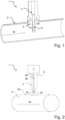
- Fig.1 is a schematic illustration of a thermometer 1 according to the prior art for measuring the temperature T of a pipeline 2 through which a medium M flows.
- the thermometer 1 is inserted into the pipeline 2 by means of a protective tube 3.
- the temperature sensor 5 is part of a measuring insert 4, which can be detachably inserted into the protective tube 3.
- the achievable measuring accuracy depends, among other things, on the respective heat dissipation W to the process environment.
- the undesired heat dissipation increases with decreasing immersion depth of the protective tube 3 into the pipeline 2, so that an increased measuring error is to be expected, especially for pipelines 2 with a small diameter.
- thermometer 1 does not protrude into the pipe 2, but is rather placed from the outside on a wall 2a of the pipe 2.
- the measuring insert 3 comprises a temperature sensor 5.
- connecting lines 6a, 6b are shown, by means of which the temperature sensor 5 can be connected to an electronics 7.
- the thermometer 1 shown has a compact design with integrated electronics 7 is designed, in other thermometers 1 the electronics 7 can also be arranged separately from the measuring insert 3.
- the temperature sensor 5 can, for example, comprise a resistance element or a thermocouple, and depending on the design of the temperature sensor 5, the number of connecting leads 6 used can vary. In this case, too, undesirable heat dissipation W to the environment occurs, which impairs the measuring accuracy of the thermometer 1.
- thermometer comprises a shaped piece 8, which is arranged in the protective tube 3 and at least partially surrounds the measuring insert 4.
- the shaped piece 8 is thus arranged at least partially between the measuring insert 4 and the protective tube 3.
- a first embodiment of a device 1 according to the invention with a shaped piece according to the invention is the subject of Fig. 3 .
- the device is a non-invasive thermometer 1 similar to the thermometer 1 of Fig. 2 .
- the shaped piece 8 is cup-shaped.
- the shaped piece 8 is arranged between the measuring insert 4 and a bottom surface of the protective tube 3 or the wall 2a of the container.
- the shaped piece 3 serves to preferably uniformly heat a volume V surrounding the temperature sensor 5 and to avoid undesirable temperature gradients in the region of the temperature sensor 5 due to heat dissipation to the environment.
- Fig. 4 Three possible, preferred embodiments for a molded part 8 according to the invention are illustrated, all of which, just like the one in Fig. 3 shown fitting can be used for both an invasive and a non-invasive thermometer.
- the fitting 8 from Fig. 4a is designed in a tube shape. In the variant shown, it has a circular cross-sectional area, but other cross-sectional areas are also possible and fall under the scope of the present invention.
- the shaped piece 8 can be in a further, not separate, but similar to the one shown in Fig. 3 shown embodiment, further have a bottom surface B. In this bottom surface B, a bore can also be arranged, through which bore the measuring insert can be guided.
- the bore then has a diameter, in particular adapted to the diameter of the measuring insert 4, which is smaller than an outer diameter of the shaped piece 8.
- the outer diameter of the shaped piece 8 is in turn adapted, for example, at least in the tubular section, to an inner diameter of the protective tube 3.
- the geometry of the shaped piece 8 can further be adapted to the geometry of the measuring insert 4 and/or the protective tube 3.
- FIG. 4b A further possible embodiment for a shaped piece 8 according to the invention is shown in Fig. 4b shown.
- the shaped piece 8 also has a cylindrical section.
- the shaped piece 8 comprises an end piece 9, whose outer diameter d 9 is larger than an outer diameter d 8 in a central region of the shaped piece 8.
- the end piece 9 is disk-shaped for the embodiment shown.
- the end piece 9 also has an optional bore through which the measuring insert 3 can be guided.
- Fig. 4c The fitting 9 shown has a tubular section and an end piece 9.
- the end piece 9 is, in contrast to Fig. 4b However, it is adapted to the geometry of the protective tube 3 or designed to correspond to it.
- thermometer 1 for invasive temperature determination, similar to the thermometer 1 from Fig. 1 .
- the thermometer 1 comprises a shaped piece 8, which is analogous to the shaped piece 8 of Fig. 4c is constructed.
- the shaped piece 8 is arranged in the protective tube 3 and partially surrounds the measuring insert 4.
- the protective tube 3 has a variable inner diameter. In a first region B 1 it has a smaller inner diameter than in a second region B 2 .
- the end piece 9 of the shaped piece 8 is arranged in a transition region between the first B1 and second region B2 of the protective tube 3 and is arranged in the transition region corresponding to the geometry of the protective tube.
- the end piece 9 thus has the function of a cover which seals off the volume V surrounding the temperature sensor 5 from the environment.
- the shaped piece 8 serves to conduct heat which flows through the protective tube 3 to the environment to the temperature sensor 5. In this way, a homogeneous temperature distribution around the temperature sensor 5 can be ensured and undesired heat dissipation W to the process environment can be avoided.
- thermometers 1 In order to ensure the best possible thermal contact between the fitting 9 and the protective tube 3 or measuring insert 4, the device 1 comprises Fig. 5 additionally optional fastening means 10. It should be noted that all embodiments shown here for thermometers 1 according to the invention can optionally have suitable fastening means 10 and that all fastening means 10 well known to the person skilled in the art are conceivable within the scope of the present invention.
- the fasteners made of Fig. 5 comprise a cylindrical base body 11, which is arranged at least partially around the shaped piece 8 in the protective tube 3, and a spring 12 for exerting a predeterminable contact pressure on the shaped piece.
- the base body 11 has a shoulder 13 on which the spring 12 is arranged.
- the base body 11 also serves to thermally insulate the molded piece 8 from the environment.
- the base body 11 for the embodiment shown is made, for example, of a heat-insulating material and is arranged such that it surrounds the cylindrical section of the molded piece.
Landscapes
- Physics & Mathematics (AREA)
- General Physics & Mathematics (AREA)
- Measuring Temperature Or Quantity Of Heat (AREA)
- Measuring And Recording Apparatus For Diagnosis (AREA)
Claims (15)
- Dispositif (1) destiné à la détermination et/ou à la surveillance d'une température d'un produit (M) dans un réservoir (2), lequel dispositif comprend :un insert de mesure (4) avec un capteur de température (5) destiné à mesurer la température (T),un doigt de gant (3) dans lequel est disposé le capteur de température (5),une pièce moulée thermoconductrice (8), laquelle est disposée dans le doigt de gant (3) et laquelle entoure l'insert de mesure (4) au moins par sections également dans une zone du capteur de température détournée du produit (M), la pièce moulée (8) étant tubulaire au moins par sections et, dans la section tubulaire de la pièce moulée (8), la pièce moulée (8) étant disposée autour de l'insert de mesure (4) dans le doigt de gant (3) et se trouvant entre l'insert de mesure (4) et le doigt de gant (3), etdes moyens de fixation (10) destinés à la fixation amovible de la pièce moulée (8) dans le doigt de gant (3) et sur l'insert de mesure (4), les moyens de fixation (10) comprenant au moins un corps de base (11) constitué d'un matériau thermo-isolant, lequel corps de base (11) est disposé autour de la pièce moulée (10) dans le doigt de gant (3).
- Dispositif (1) selon la revendication 1,
pour lequel la pièce moulée (8) est fabriquée en cuivre, en argent, en graphite, en nitrure de bore, en un acier, notamment un acier inoxydable, ou en un alliage comprenant au moins l'un de ces matériaux. - Dispositif (1) selon la revendication 1 ou 2,
pour lequel la pièce moulée (8) est conçue en forme de cylindre au moins par sections. - Dispositif (1) selon au moins l'une des revendications précédentes,
pour lequel la pièce moulée (8) est conçue en forme de godet. - Dispositif (1) selon la revendication 4,
pour lequel une surface de fond (B) de la pièce moulée (8) présente un alésage à travers lequel l'insert de mesure (4) peut être guidé. - Dispositif (1) selon la revendication 5,
pour lequel la surface de fond est disposée sur un côté du capteur de température qui doit être détourné du produit. - Dispositif (1) selon au moins l'une des revendications précédentes,
pour lequel la pièce moulée (8) présente au moins par sections une géométrie correspondant à une géométrie du doigt de gant (3) et/ou de l'insert de mesure (4). - Dispositif (1) selon au moins l'une des revendications précédentes,
pour lequel la pièce moulée (8) comporte un pièce d'extrémité (9) dont le diamètre extérieur (d9) est supérieur à un diamètre extérieur (d8) de la pièce moulée (8) dans une zone centrale de la pièce moulée (8). - Dispositif (1) selon la revendication 8,
pour lequel la pièce d'extrémité (9) est conçue en forme de disque. - Dispositif (1) selon la revendication 8 ou 9,
pour lequel une géométrie de la pièce d'extrémité (9) est conçue de manière à correspondre au moins partiellement à une géométrie du doigt de gant (3) dans une zone dans laquelle la pièce moulée (8) peut être introduite. - Dispositif (1) selon au moins l'une des revendications précédentes,
pour lequel les moyens de fixation (10) sont conçus et disposés de telle sorte qu'une force de pression, notamment prédéfinissable, peut être exercée sur la pièce moulée (8) par l'intermédiaire des moyens de fixation (10). - Dispositif (1) selon au moins l'une des revendications précédentes,
pour lequel le corps de base est cylindrique. - Dispositif (1) selon au moins l'une des revendications précédentes,
pour lequel le corps de base (11) est fabriqué en une matière plastique, notamment en PEEK, PEK ou PPS. - Dispositif (1) selon au moins l'une des revendications précédentes,
pour lequel les moyens de fixation (10) comportent au moins un ressort (12), ressort (12) par lequel la force de pression prédéfinissable peut être transmise au moyen du corps de base (11). - Dispositif (1) selon au moins l'une des revendications précédentes,
pour lequel le capteur de température (5) comprend au moins un élément résistif ou un thermocouple.
Applications Claiming Priority (2)
| Application Number | Priority Date | Filing Date | Title |
|---|---|---|---|
| DE102019124606.7A DE102019124606A1 (de) | 2019-09-12 | 2019-09-12 | Thermometer |
| PCT/EP2020/073391 WO2021047883A1 (fr) | 2019-09-12 | 2020-08-20 | Thermomètre |
Publications (2)
| Publication Number | Publication Date |
|---|---|
| EP4028736A1 EP4028736A1 (fr) | 2022-07-20 |
| EP4028736B1 true EP4028736B1 (fr) | 2025-03-26 |
Family
ID=72193458
Family Applications (1)
| Application Number | Title | Priority Date | Filing Date |
|---|---|---|---|
| EP20760826.6A Active EP4028736B1 (fr) | 2019-09-12 | 2020-08-20 | Thermomètre |
Country Status (5)
| Country | Link |
|---|---|
| US (1) | US12253419B2 (fr) |
| EP (1) | EP4028736B1 (fr) |
| CN (1) | CN114430802B (fr) |
| DE (1) | DE102019124606A1 (fr) |
| WO (1) | WO2021047883A1 (fr) |
Family Cites Families (19)
| Publication number | Priority date | Publication date | Assignee | Title |
|---|---|---|---|---|
| US3281518A (en) * | 1963-11-26 | 1966-10-25 | Leeds & Northrup Co | Thermocouple assembly |
| CH647867A5 (en) * | 1980-09-29 | 1985-02-15 | Landis & Gyr Ag | Temperature sensor |
| US4959633A (en) * | 1989-09-05 | 1990-09-25 | General Motors Corporation | Temperature sender connector cover and terminal |
| DE4030656A1 (de) * | 1990-09-28 | 1992-04-02 | Vdo Schindling | Temperatur-messwertgeber |
| US5709475A (en) * | 1995-07-11 | 1998-01-20 | Larry E. Smith | Powerboat outdrive vent plug mounted temperature detection device |
| JP3313555B2 (ja) * | 1995-10-05 | 2002-08-12 | 新日本製鐵株式会社 | 高炉炉底温度計 |
| US7090658B2 (en) * | 1997-03-03 | 2006-08-15 | Medical Solutions, Inc. | Temperature sensing device for selectively measuring temperature at desired locations along an intravenous fluid line |
| JP3603614B2 (ja) * | 1998-09-16 | 2004-12-22 | いすゞ自動車株式会社 | 熱電対 |
| US6485175B1 (en) * | 1999-08-06 | 2002-11-26 | Pgi International, Ltd. | Temperature sensing device for metering fluids |
| CN2425354Y (zh) * | 1999-12-17 | 2001-03-28 | 乐清市华东仪表厂 | 间隙前置式隔爆热电偶(阻) |
| EP2093548B1 (fr) * | 2008-02-20 | 2017-03-22 | UST Umweltsensortechnik GmbH | Capteur de haute température et son procédé de fabrication |
| JP5134701B2 (ja) * | 2010-07-20 | 2013-01-30 | 日本特殊陶業株式会社 | 温度センサ |
| US9188490B2 (en) * | 2013-03-12 | 2015-11-17 | Rosemount Inc. | Thermowell insert |
| US9523650B2 (en) * | 2013-09-06 | 2016-12-20 | Conax Technologies Llc | Spring loaded exhaust gas temperature sensor assembly |
| EP3112830B1 (fr) * | 2015-07-01 | 2018-08-22 | Sensata Technologies, Inc. | Capteur de température et procédé de production associé |
| CN206095444U (zh) * | 2016-08-02 | 2017-04-12 | 宁夏万仕隆冷冻科技股份有限公司 | 一种弹簧压紧式温度变送器保护套管 |
| JP7021229B2 (ja) * | 2016-12-30 | 2022-02-16 | ローズマウント インコーポレイテッド | 調節可能なばねが装備された温度センサ用アダプタ |
| CN108332874A (zh) * | 2017-01-20 | 2018-07-27 | 广东美的生活电器制造有限公司 | 温度传感器组件和料理机 |
| JP2020118530A (ja) * | 2019-01-23 | 2020-08-06 | アズビル株式会社 | 温度センサおよび熱量計測システム |
-
2019
- 2019-09-12 DE DE102019124606.7A patent/DE102019124606A1/de active Pending
-
2020
- 2020-08-20 CN CN202080063614.8A patent/CN114430802B/zh active Active
- 2020-08-20 EP EP20760826.6A patent/EP4028736B1/fr active Active
- 2020-08-20 US US17/642,440 patent/US12253419B2/en active Active
- 2020-08-20 WO PCT/EP2020/073391 patent/WO2021047883A1/fr not_active Ceased
Also Published As
| Publication number | Publication date |
|---|---|
| CN114430802B (zh) | 2026-01-23 |
| CN114430802A (zh) | 2022-05-03 |
| EP4028736A1 (fr) | 2022-07-20 |
| US12253419B2 (en) | 2025-03-18 |
| DE102019124606A1 (de) | 2021-03-18 |
| US20220341794A1 (en) | 2022-10-27 |
| WO2021047883A1 (fr) | 2021-03-18 |
Similar Documents
| Publication | Publication Date | Title |
|---|---|---|
| EP3688430B1 (fr) | Dispositif de mesure de température et procédé de détermination de température | |
| EP3818348B1 (fr) | Thermomètre comprenant une fonction de diagnostic | |
| EP4052004B1 (fr) | Thermomètre non invasif | |
| DE102008060123B3 (de) | Hochtemperatursensor | |
| EP3791147B1 (fr) | Insert de mesure comportant une gaine de protection | |
| EP4028734B1 (fr) | Thermomètre non invasif | |
| WO2022218649A1 (fr) | Élément de couplage pour un dispositif servant à déterminer et/ou à surveiller une grandeur de processus | |
| EP4264213B1 (fr) | Thermomètre avec fonction de diagnostic | |
| EP4028735B1 (fr) | Thermomètre non invasif | |
| EP3655730B1 (fr) | Débitmètre thermique | |
| EP4367490A1 (fr) | Thermomètre à précision de mesure améliorée | |
| WO2021047884A1 (fr) | Thermomètre non invasif | |
| WO2021047883A1 (fr) | Thermomètre | |
| EP4078121B1 (fr) | Thermomètre ayant une fonction de compensation | |
| EP4377646B1 (fr) | Diagnostic d'un thermomètre | |
| EP4078101B1 (fr) | Dispositif de mesure | |
| WO2020001875A1 (fr) | Étalonneur de température | |
| DE102019124603A1 (de) | Nicht invasives Thermometer |
Legal Events
| Date | Code | Title | Description |
|---|---|---|---|
| STAA | Information on the status of an ep patent application or granted ep patent |
Free format text: STATUS: UNKNOWN |
|
| STAA | Information on the status of an ep patent application or granted ep patent |
Free format text: STATUS: THE INTERNATIONAL PUBLICATION HAS BEEN MADE |
|
| PUAI | Public reference made under article 153(3) epc to a published international application that has entered the european phase |
Free format text: ORIGINAL CODE: 0009012 |
|
| STAA | Information on the status of an ep patent application or granted ep patent |
Free format text: STATUS: REQUEST FOR EXAMINATION WAS MADE |
|
| 17P | Request for examination filed |
Effective date: 20220221 |
|
| AK | Designated contracting states |
Kind code of ref document: A1 Designated state(s): AL AT BE BG CH CY CZ DE DK EE ES FI FR GB GR HR HU IE IS IT LI LT LU LV MC MK MT NL NO PL PT RO RS SE SI SK SM TR |
|
| DAV | Request for validation of the european patent (deleted) | ||
| DAX | Request for extension of the european patent (deleted) | ||
| STAA | Information on the status of an ep patent application or granted ep patent |
Free format text: STATUS: EXAMINATION IS IN PROGRESS |
|
| 17Q | First examination report despatched |
Effective date: 20240724 |
|
| REG | Reference to a national code |
Ref country code: DE Ref legal event code: R079 Free format text: PREVIOUS MAIN CLASS: G01K0001140000 Ipc: G01K0001143000 Ref country code: DE Ref legal event code: R079 Ref document number: 502020010697 Country of ref document: DE Free format text: PREVIOUS MAIN CLASS: G01K0001140000 Ipc: G01K0001143000 |
|
| GRAP | Despatch of communication of intention to grant a patent |
Free format text: ORIGINAL CODE: EPIDOSNIGR1 |
|
| STAA | Information on the status of an ep patent application or granted ep patent |
Free format text: STATUS: GRANT OF PATENT IS INTENDED |
|
| RIC1 | Information provided on ipc code assigned before grant |
Ipc: G01K 1/16 20060101ALI20241101BHEP Ipc: G01K 13/02 20210101ALI20241101BHEP Ipc: G01K 1/143 20210101AFI20241101BHEP |
|
| INTG | Intention to grant announced |
Effective date: 20241119 |
|
| GRAS | Grant fee paid |
Free format text: ORIGINAL CODE: EPIDOSNIGR3 |
|
| GRAA | (expected) grant |
Free format text: ORIGINAL CODE: 0009210 |
|
| STAA | Information on the status of an ep patent application or granted ep patent |
Free format text: STATUS: THE PATENT HAS BEEN GRANTED |
|
| AK | Designated contracting states |
Kind code of ref document: B1 Designated state(s): AL AT BE BG CH CY CZ DE DK EE ES FI FR GB GR HR HU IE IS IT LI LT LU LV MC MK MT NL NO PL PT RO RS SE SI SK SM TR |
|
| REG | Reference to a national code |
Ref country code: GB Ref legal event code: FG4D Free format text: NOT ENGLISH |
|
| REG | Reference to a national code |
Ref country code: CH Ref legal event code: EP |
|
| REG | Reference to a national code |
Ref country code: DE Ref legal event code: R096 Ref document number: 502020010697 Country of ref document: DE |
|
| REG | Reference to a national code |
Ref country code: IE Ref legal event code: FG4D Free format text: LANGUAGE OF EP DOCUMENT: GERMAN |
|
| P01 | Opt-out of the competence of the unified patent court (upc) registered |
Free format text: CASE NUMBER: APP_14084/2025 Effective date: 20250321 |
|
| PG25 | Lapsed in a contracting state [announced via postgrant information from national office to epo] |
Ref country code: RS Free format text: LAPSE BECAUSE OF FAILURE TO SUBMIT A TRANSLATION OF THE DESCRIPTION OR TO PAY THE FEE WITHIN THE PRESCRIBED TIME-LIMIT Effective date: 20250626 |
|
| PG25 | Lapsed in a contracting state [announced via postgrant information from national office to epo] |
Ref country code: FI Free format text: LAPSE BECAUSE OF FAILURE TO SUBMIT A TRANSLATION OF THE DESCRIPTION OR TO PAY THE FEE WITHIN THE PRESCRIBED TIME-LIMIT Effective date: 20250326 |
|
| REG | Reference to a national code |
Ref country code: LT Ref legal event code: MG9D |
|
| PG25 | Lapsed in a contracting state [announced via postgrant information from national office to epo] |
Ref country code: NO Free format text: LAPSE BECAUSE OF FAILURE TO SUBMIT A TRANSLATION OF THE DESCRIPTION OR TO PAY THE FEE WITHIN THE PRESCRIBED TIME-LIMIT Effective date: 20250626 |
|
| PG25 | Lapsed in a contracting state [announced via postgrant information from national office to epo] |
Ref country code: HR Free format text: LAPSE BECAUSE OF FAILURE TO SUBMIT A TRANSLATION OF THE DESCRIPTION OR TO PAY THE FEE WITHIN THE PRESCRIBED TIME-LIMIT Effective date: 20250326 |
|
| PG25 | Lapsed in a contracting state [announced via postgrant information from national office to epo] |
Ref country code: LV Free format text: LAPSE BECAUSE OF FAILURE TO SUBMIT A TRANSLATION OF THE DESCRIPTION OR TO PAY THE FEE WITHIN THE PRESCRIBED TIME-LIMIT Effective date: 20250326 |
|
| PG25 | Lapsed in a contracting state [announced via postgrant information from national office to epo] |
Ref country code: GR Free format text: LAPSE BECAUSE OF FAILURE TO SUBMIT A TRANSLATION OF THE DESCRIPTION OR TO PAY THE FEE WITHIN THE PRESCRIBED TIME-LIMIT Effective date: 20250627 Ref country code: BG Free format text: LAPSE BECAUSE OF FAILURE TO SUBMIT A TRANSLATION OF THE DESCRIPTION OR TO PAY THE FEE WITHIN THE PRESCRIBED TIME-LIMIT Effective date: 20250326 |
|
| REG | Reference to a national code |
Ref country code: NL Ref legal event code: MP Effective date: 20250326 |
|
| PG25 | Lapsed in a contracting state [announced via postgrant information from national office to epo] |
Ref country code: NL Free format text: LAPSE BECAUSE OF FAILURE TO SUBMIT A TRANSLATION OF THE DESCRIPTION OR TO PAY THE FEE WITHIN THE PRESCRIBED TIME-LIMIT Effective date: 20250326 |
|
| PG25 | Lapsed in a contracting state [announced via postgrant information from national office to epo] |
Ref country code: SE Free format text: LAPSE BECAUSE OF FAILURE TO SUBMIT A TRANSLATION OF THE DESCRIPTION OR TO PAY THE FEE WITHIN THE PRESCRIBED TIME-LIMIT Effective date: 20250326 |
|
| PG25 | Lapsed in a contracting state [announced via postgrant information from national office to epo] |
Ref country code: SM Free format text: LAPSE BECAUSE OF FAILURE TO SUBMIT A TRANSLATION OF THE DESCRIPTION OR TO PAY THE FEE WITHIN THE PRESCRIBED TIME-LIMIT Effective date: 20250326 |
|
| PG25 | Lapsed in a contracting state [announced via postgrant information from national office to epo] |
Ref country code: ES Free format text: LAPSE BECAUSE OF FAILURE TO SUBMIT A TRANSLATION OF THE DESCRIPTION OR TO PAY THE FEE WITHIN THE PRESCRIBED TIME-LIMIT Effective date: 20250326 Ref country code: PT Free format text: LAPSE BECAUSE OF FAILURE TO SUBMIT A TRANSLATION OF THE DESCRIPTION OR TO PAY THE FEE WITHIN THE PRESCRIBED TIME-LIMIT Effective date: 20250728 |
|
| PGFP | Annual fee paid to national office [announced via postgrant information from national office to epo] |
Ref country code: DE Payment date: 20250820 Year of fee payment: 6 |
|
| PG25 | Lapsed in a contracting state [announced via postgrant information from national office to epo] |
Ref country code: PL Free format text: LAPSE BECAUSE OF FAILURE TO SUBMIT A TRANSLATION OF THE DESCRIPTION OR TO PAY THE FEE WITHIN THE PRESCRIBED TIME-LIMIT Effective date: 20250326 |
|
| PGFP | Annual fee paid to national office [announced via postgrant information from national office to epo] |
Ref country code: IT Payment date: 20250825 Year of fee payment: 6 |
|
| PGFP | Annual fee paid to national office [announced via postgrant information from national office to epo] |
Ref country code: FR Payment date: 20250828 Year of fee payment: 6 |
|
| PG25 | Lapsed in a contracting state [announced via postgrant information from national office to epo] |
Ref country code: EE Free format text: LAPSE BECAUSE OF FAILURE TO SUBMIT A TRANSLATION OF THE DESCRIPTION OR TO PAY THE FEE WITHIN THE PRESCRIBED TIME-LIMIT Effective date: 20250326 |
|
| PG25 | Lapsed in a contracting state [announced via postgrant information from national office to epo] |
Ref country code: RO Free format text: LAPSE BECAUSE OF FAILURE TO SUBMIT A TRANSLATION OF THE DESCRIPTION OR TO PAY THE FEE WITHIN THE PRESCRIBED TIME-LIMIT Effective date: 20250326 |
|
| PG25 | Lapsed in a contracting state [announced via postgrant information from national office to epo] |
Ref country code: SK Free format text: LAPSE BECAUSE OF FAILURE TO SUBMIT A TRANSLATION OF THE DESCRIPTION OR TO PAY THE FEE WITHIN THE PRESCRIBED TIME-LIMIT Effective date: 20250326 |
|
| PG25 | Lapsed in a contracting state [announced via postgrant information from national office to epo] |
Ref country code: IS Free format text: LAPSE BECAUSE OF FAILURE TO SUBMIT A TRANSLATION OF THE DESCRIPTION OR TO PAY THE FEE WITHIN THE PRESCRIBED TIME-LIMIT Effective date: 20250726 |
|
| REG | Reference to a national code |
Ref country code: DE Ref legal event code: R097 Ref document number: 502020010697 Country of ref document: DE |
|
| PG25 | Lapsed in a contracting state [announced via postgrant information from national office to epo] |
Ref country code: DK Free format text: LAPSE BECAUSE OF FAILURE TO SUBMIT A TRANSLATION OF THE DESCRIPTION OR TO PAY THE FEE WITHIN THE PRESCRIBED TIME-LIMIT Effective date: 20250326 |
|
| PG25 | Lapsed in a contracting state [announced via postgrant information from national office to epo] |
Ref country code: CZ Free format text: LAPSE BECAUSE OF FAILURE TO SUBMIT A TRANSLATION OF THE DESCRIPTION OR TO PAY THE FEE WITHIN THE PRESCRIBED TIME-LIMIT Effective date: 20250326 |
|
| PLBE | No opposition filed within time limit |
Free format text: ORIGINAL CODE: 0009261 |
|
| STAA | Information on the status of an ep patent application or granted ep patent |
Free format text: STATUS: NO OPPOSITION FILED WITHIN TIME LIMIT |
|
| REG | Reference to a national code |
Ref country code: CH Ref legal event code: L10 Free format text: ST27 STATUS EVENT CODE: U-0-0-L10-L00 (AS PROVIDED BY THE NATIONAL OFFICE) Effective date: 20260211 |
|
| 26N | No opposition filed |
Effective date: 20260105 |
|
| REG | Reference to a national code |
Ref country code: CH Ref legal event code: H13 Free format text: ST27 STATUS EVENT CODE: U-0-0-H10-H13 (AS PROVIDED BY THE NATIONAL OFFICE) Effective date: 20260324 |
|
| PG25 | Lapsed in a contracting state [announced via postgrant information from national office to epo] |
Ref country code: MC Free format text: LAPSE BECAUSE OF FAILURE TO SUBMIT A TRANSLATION OF THE DESCRIPTION OR TO PAY THE FEE WITHIN THE PRESCRIBED TIME-LIMIT Effective date: 20250326 |
|
| PG25 | Lapsed in a contracting state [announced via postgrant information from national office to epo] |
Ref country code: LU Free format text: LAPSE BECAUSE OF NON-PAYMENT OF DUE FEES Effective date: 20250820 |
|
| PG25 | Lapsed in a contracting state [announced via postgrant information from national office to epo] |
Ref country code: CH Free format text: LAPSE BECAUSE OF NON-PAYMENT OF DUE FEES Effective date: 20250831 |
|
| GBPC | Gb: european patent ceased through non-payment of renewal fee |
Effective date: 20250820 |