EP4052004B1 - Thermomètre non invasif - Google Patents
Thermomètre non invasif Download PDFInfo
- Publication number
- EP4052004B1 EP4052004B1 EP20797741.4A EP20797741A EP4052004B1 EP 4052004 B1 EP4052004 B1 EP 4052004B1 EP 20797741 A EP20797741 A EP 20797741A EP 4052004 B1 EP4052004 B1 EP 4052004B1
- Authority
- EP
- European Patent Office
- Prior art keywords
- container
- temperature sensor
- temperature
- section
- wall
- Prior art date
- Legal status (The legal status is an assumption and is not a legal conclusion. Google has not performed a legal analysis and makes no representation as to the accuracy of the status listed.)
- Active
Links
Images
Classifications
-
- G—PHYSICS
- G01—MEASURING; TESTING
- G01F—MEASURING VOLUME, VOLUME FLOW, MASS FLOW OR LIQUID LEVEL; METERING BY VOLUME
- G01F1/00—Measuring the volume flow or mass flow of fluid or fluent solid material wherein the fluid passes through a meter in a continuous flow
- G01F1/68—Measuring the volume flow or mass flow of fluid or fluent solid material wherein the fluid passes through a meter in a continuous flow by using thermal effects
- G01F1/684—Structural arrangements; Mounting of elements, e.g. in relation to fluid flow
-
- G—PHYSICS
- G01—MEASURING; TESTING
- G01D—MEASURING NOT SPECIALLY ADAPTED FOR A SPECIFIC VARIABLE; ARRANGEMENTS FOR MEASURING TWO OR MORE VARIABLES NOT COVERED IN A SINGLE OTHER SUBCLASS; TARIFF METERING APPARATUS; MEASURING OR TESTING NOT OTHERWISE PROVIDED FOR
- G01D21/00—Measuring or testing not otherwise provided for
- G01D21/02—Measuring two or more variables by means not covered by a single other subclass
-
- G—PHYSICS
- G01—MEASURING; TESTING
- G01F—MEASURING VOLUME, VOLUME FLOW, MASS FLOW OR LIQUID LEVEL; METERING BY VOLUME
- G01F1/00—Measuring the volume flow or mass flow of fluid or fluent solid material wherein the fluid passes through a meter in a continuous flow
- G01F1/68—Measuring the volume flow or mass flow of fluid or fluent solid material wherein the fluid passes through a meter in a continuous flow by using thermal effects
- G01F1/684—Structural arrangements; Mounting of elements, e.g. in relation to fluid flow
- G01F1/688—Structural arrangements; Mounting of elements, e.g. in relation to fluid flow using a particular type of heating, cooling or sensing element
- G01F1/6888—Thermoelectric elements, e.g. thermocouples, thermopiles
-
- G—PHYSICS
- G01—MEASURING; TESTING
- G01F—MEASURING VOLUME, VOLUME FLOW, MASS FLOW OR LIQUID LEVEL; METERING BY VOLUME
- G01F1/00—Measuring the volume flow or mass flow of fluid or fluent solid material wherein the fluid passes through a meter in a continuous flow
- G01F1/68—Measuring the volume flow or mass flow of fluid or fluent solid material wherein the fluid passes through a meter in a continuous flow by using thermal effects
- G01F1/684—Structural arrangements; Mounting of elements, e.g. in relation to fluid flow
- G01F1/688—Structural arrangements; Mounting of elements, e.g. in relation to fluid flow using a particular type of heating, cooling or sensing element
- G01F1/69—Structural arrangements; Mounting of elements, e.g. in relation to fluid flow using a particular type of heating, cooling or sensing element of resistive type
-
- G—PHYSICS
- G01—MEASURING; TESTING
- G01K—MEASURING TEMPERATURE; MEASURING QUANTITY OF HEAT; THERMALLY-SENSITIVE ELEMENTS NOT OTHERWISE PROVIDED FOR
- G01K1/00—Details of thermometers not specially adapted for particular types of thermometer
- G01K1/14—Supports; Fastening devices; Arrangements for mounting thermometers in particular locations
- G01K1/143—Supports; Fastening devices; Arrangements for mounting thermometers in particular locations for measuring surface temperatures
-
- G—PHYSICS
- G01—MEASURING; TESTING
- G01K—MEASURING TEMPERATURE; MEASURING QUANTITY OF HEAT; THERMALLY-SENSITIVE ELEMENTS NOT OTHERWISE PROVIDED FOR
- G01K13/00—Thermometers specially adapted for specific purposes
- G01K13/02—Thermometers specially adapted for specific purposes for measuring temperature of moving fluids or granular materials capable of flow
-
- G—PHYSICS
- G01—MEASURING; TESTING
- G01K—MEASURING TEMPERATURE; MEASURING QUANTITY OF HEAT; THERMALLY-SENSITIVE ELEMENTS NOT OTHERWISE PROVIDED FOR
- G01K15/00—Testing or calibrating of thermometers
- G01K15/005—Calibration
-
- G—PHYSICS
- G01—MEASURING; TESTING
- G01P—MEASURING LINEAR OR ANGULAR SPEED, ACCELERATION, DECELERATION, OR SHOCK; INDICATING PRESENCE, ABSENCE, OR DIRECTION, OF MOVEMENT
- G01P5/00—Measuring speed of fluids, e.g. of air stream; Measuring speed of bodies relative to fluids, e.g. of ship, of aircraft
- G01P5/10—Measuring speed of fluids, e.g. of air stream; Measuring speed of bodies relative to fluids, e.g. of ship, of aircraft by measuring thermal variables
- G01P5/12—Measuring speed of fluids, e.g. of air stream; Measuring speed of bodies relative to fluids, e.g. of ship, of aircraft by measuring thermal variables using variation of resistance of a heated conductor
Definitions
- the invention relates to a device for determining and/or monitoring a process variable, in particular the temperature, flow rate, or flow velocity of a medium in a container, for example in automation technology.
- the container is, for example, a tank or a pipeline.
- Thermometers have become known in a wide variety of designs from the state of the art. There are thermometers that use the expansion of a liquid, gas, or solid with a known coefficient of expansion to measure temperature, and there are also those that relate the electrical conductivity of a material or a derived value to temperature, such as electrical resistance when using resistance elements or the thermoelectric effect in the case of thermocouples. In contrast, radiation thermometers, especially pyrometers, utilize the thermal radiation of a substance to determine its temperature. The underlying measurement principles have been described in numerous publications.
- Temperature sensors in the form of resistance elements include thin-film and thick-film sensors, as well as NTC thermistors.
- a thin-film sensor particularly a resistance temperature detector (RTD) uses a sensor element with connecting wires applied to a carrier substrate. The back of the carrier substrate is usually coated with metal.
- Sensor elements used are so-called resistance elements, which are made of platinum elements, for example. These are also commercially available under the designations PT10, PT100, and PT1000, among others.
- thermocouples In temperature sensors in the form of thermocouples, the temperature is determined by a thermoelectric voltage that develops between thermocouple wires made of different materials connected at one end.
- Thermocouples according to DIN standard IEC584, e.g., thermocouples of type K, J, N, S, R, B, T, or E, are typically used as temperature sensors for temperature measurement.
- other material pairs, especially those with a measurable Seebeck effect are also possible.
- the accuracy of the temperature measurement depends sensitively on the respective thermal contacts and the prevailing heat conduction. Heat flows between the medium, the container containing the medium, the thermometer, and the process environment play a crucial role here. For reliable temperature determination, it is important that the respective temperature sensor and the medium are essentially in thermal equilibrium for at least the time required to record the temperature. The time it takes for a thermometer to react to a temperature change is also referred to as the thermometer's response time.
- thermometers have been developed in which the temperature sensor is placed more or less directly in contact with the medium. This allows for a comparatively good coupling between the medium and the temperature sensor.
- thermometers often use measuring inserts with temperature sensors in the form of thermocouples that are welded directly to the outer surface or skin of the pipe or vessel. In such cases, however, replacing the thermocouples can be a time-consuming and costly process, especially because replacement may require a temporary shutdown of the process and/or application.
- US5382093 or the previously unpublished European patent application with the reference 18198608.4 Designs of corresponding thermometers have become known which enable easy replacement of the temperature sensors.
- thermometers for non-invasive temperature measurement have become known, as for example in the documents US2013/070808A1 , US2016/0047697A1 , DE102005040699B3 , EP3230704B1 or EP2038625B1 described.
- a key problem with non-invasive temperature determination is the heat dissipation from the process to the environment. This results in a significantly higher measurement error than in the case of directly inserting the respective temperature sensor into the process.
- Such field devices typically comprise at least two sensor elements with at least one temperature sensor and at least one heating element or heatable temperature sensor.
- the sensor elements can be inserted into the respective pipeline or integrated into or onto a measuring tube (non-invasive design).
- the object of the invention is to provide a possibility for temperature determination, in particular for thermometers and measuring devices for determining a flow or a flow velocity, which is characterized by a high measurement accuracy.
- the device according to the invention comprises a temperature sensor for detecting the temperature, which temperature sensor can be fastened to an outer wall of the container, at least one connecting line for electrically contacting the temperature sensor, and fastening means for, in particular detachably, fastening the temperature sensor and a section of the connecting line facing the temperature sensor to the outer wall of the container.
- At least the section of the connecting line can be fastened to the outer wall of the container in such a way that the section runs along the wall of the container and is in thermal contact with the wall of the container.
- the temperature sensor and a section of the connecting cable are therefore guided along the wall of the container, for example a pipe, and connected to attached thereto.
- An alignment of the respective section along the wall of the container is understood to mean, on the one hand, an at least partial course of the section of the connecting line essentially parallel to the wall, in particular parallel to a longitudinal axis of the wall.
- the section it is also conceivable for the section to be at least partially wrapped around the wall, i.e. to be arranged following the circumference of the pipeline.
- numerous other courses are also conceivable, for example a meandering structure of the connecting line in the section.
- the at least one connecting line in said section follows the contours of the wall of the container.
- the temperature of the medium is therefore determined indirectly via a container wall.
- the selected orientation of the connecting line relative to the container wall significantly increases the contact area between the temperature sensor, the section of the connecting line facing the temperature sensor, and the pipe. This significantly increases heat conduction from the medium across the container wall to the temperature sensor and the section of the connecting line facing the temperature sensor. In addition, a temperature gradient in the section of the connecting line facing the temperature sensor is significantly reduced.
- the temperature sensor and the section of at least one connecting line can be applied directly to the pipeline.
- the temperature sensor and the connecting line can be part of a measuring insert, and for the measuring insert to be attached to the pipeline.
- the device can optionally further comprise electronics.
- the electronics can also be a separate component that can be connected to the device. If the temperature sensor is contacted by more than one connecting cable, the sections of all connecting cables facing the temperature sensor are preferably aligned parallel to the pipeline.
- fastening means all fastening means customary and suitable to those skilled in the art, such as clamps or pipe clamps, are suitable and fall within the scope of the present invention.
- One embodiment includes the temperature sensor being a resistance element or a thermocouple.
- a further embodiment includes that the device comprises at least one reference element for in situ calibration and/or validation of at least the temperature sensor, which reference element is attached to the outer wall of the container, and which reference element consists at least partially of at least one material, for which material in the temperature range relevant for the calibration of the first temperature sensor at least one phase transition occurs at at least one predetermined phase transition temperature, for which phase transition the material remains in the solid phase.
- reference element for in situ calibration and/or validation of at least the temperature sensor, which reference element is attached to the outer wall of the container, and which reference element consists at least partially of at least one material, for which material in the temperature range relevant for the calibration of the first temperature sensor at least one phase transition occurs at at least one predetermined phase transition temperature, for which phase transition the material remains in the solid phase.
- the device comprises a heating element which is attached to the outer wall of the container.
- the heating unit By means of the heating unit, the device can It can also be heated to a predeterminable temperature.
- a design with a heating element is particularly advantageous when the device is used to determine the flow rate according to the thermal flow measurement principle.
- the term "flow rate" includes both a volume flow rate and a mass flow rate of the medium. Likewise, a flow velocity or flow rate of the medium can be determined.
- flow can be determined in two different ways.
- a sensor element is heated such that its temperature remains essentially constant.
- the medium properties are known and at least temporarily constant, such as the medium temperature, its density or composition
- the mass flow of the medium through the pipeline can be determined based on the heating power required to maintain the temperature at a constant value.
- the medium temperature is understood to be the temperature the medium has without additional heat input from a heating element.
- the heating element is operated with a constant heating power and the temperature of the medium is measured downstream of the heating element. In this case, the measured temperature of the medium provides information about the mass flow.
- other measuring principles have also become known, for example so-called transient methods in which the heating power or the temperature is modulated.
- the heating element can, for example, be designed in the form of a resistance heater, which is heated by converting the electrical power supplied to it, e.g. as a result of an increased current supply.
- the temperature sensor comprises a temperature-sensitive sensor element which is electrically contacted via at least a first and a second connecting line, wherein the first connecting line is divided into a first and a second section, wherein the first section facing the sensor element consists of a first material, and wherein the second section facing away from the sensor element consists of a second material different from the first, wherein the second connecting line consists of the second material, and wherein the first section of the first connecting line and at least a part of the second connecting line form a first differential temperature sensor in the form of a thermocouple.
- the first connecting line is divided into a first and a second section, wherein the first section facing the sensor element consists of a first material, and wherein the second section facing away from the sensor element consists of a second material different from the first, wherein the second connecting line consists of the second material, and wherein the first section of the first connecting line and at least a part of the second connecting line form a first differential temperature sensor in the form of a thermocouple.
- the device comprises a thermally conductive coupling unit that can be attached to the outer wall of the container.
- the coupling unit serves to further improve the thermal contact between the temperature sensor, the section of the connecting line, and the medium or the outer wall of the container.
- the coupling unit is made, for example, of a thermally conductive material, in particular copper or silver.
- the coupling unit at least partially comprises a material with anisotropic thermal conductivity, preferably a material containing at least partially carbon, in particular graphite, or hexagonal boron nitride.
- the coupling unit comprises a layer or a coating, which layer or coating consists at least partially of the material with anisotropic thermal conductivity.
- the layer preferably has a higher thermal conductivity in the longitudinal direction, i.e. along a plane parallel to the layer or coating, than perpendicular to it or perpendicular to the plane.
- the coupling unit comprises a thin-walled film, which film consists at least partially of the material with anisotropic thermal conductivity.
- the film also preferably has a higher thermal conductivity along its longitudinal axis than perpendicular to it.
- the coupling unit is arranged such that it surrounds at least the temperature sensor, a portion of the connecting line section, and/or a portion of the container.
- the coupling unit is preferably in thermal contact with the container, the temperature sensor, and the connecting line section. It serves to conduct additional heat from the process to the temperature sensor and reduces a temperature gradient in the region of the temperature sensor and the connecting line section.
- the coupling unit thus serves to distribute heat from the process to the areas of the temperature sensor and the section facing away from the process the connecting cable. Furthermore, it ensures that all components of the device are always in thermal equilibrium with each other.
- the coupling unit is an elongate element which has a small thickness compared to a surface, for example a thin-walled film, or a layer arrangement of at least two films.
- the device comprises a housing which can be fastened to the outer wall of the container and is designed such that, when fastened to the wall, it surrounds at least the temperature sensor and the section of the connecting line.
- thermometers without limitation.
- the respective considerations can be easily applied to other types of field devices, such as thermal flow meters.
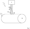
- thermometer 1 A schematic illustration of a thermometer 1 according to the prior art with a measuring insert 3 and electronics 4 is shown.
- the thermometer 1 is used to measure the temperature T of a medium M, which is located in a container 2, here in the form of a pipeline.
- the thermometer 1 does not protrude into the pipeline 2, but rather is placed on a wall W of the pipeline 2 for non-invasive temperature determination from the outside.
- the measuring insert 3 comprises a temperature sensor 5, which in the present case comprises a temperature-sensitive element in the form of a resistance element.
- the temperature sensor 5 is electrically contacted via the connecting lines 6a, 6b and connected to the electronics 4.
- thermometer 1 shown is designed in a compact design with integrated electronics 4, in other thermometers 1 the electronics 4 can also be arranged separately from the measuring insert 3.
- the temperature sensor 5 does not necessarily have to be a resistance element, and the number of connecting lines 6 used does not have to be necessarily be two. Rather, the number of connecting cables 6 can be selected depending on the measuring principle used and the temperature sensor 5 used.
- thermometer 1 the measuring accuracy of such a thermometer 1 depends to a large extent on the materials used for the thermometer and on the respective, particularly thermal, contacts, especially in the area of the temperature sensor 5.
- the temperature sensor 5 is in indirect thermal contact with the medium M, i.e., via the measuring insert 3 and the wall W of the container 2. Heat dissipation from the medium M to the environment also plays a major role in this context, which can lead to an undesirable temperature gradient in the area of the temperature sensor 5.
- a device 1 according to the invention can also be used in conjunction with containers, receptacles, or other types of receptacles 2.
- the present invention is by no means limited to configurations with two connecting lines 6a, 6b. Rather, depending on the type of temperature sensor 5 and the measuring principle used, different numbers of connecting lines 6a, 6b may be required.
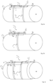
- the temperature sensor 5 and at least the section a of the connecting lines 6a,6b can also be part of a measuring insert 3, as in Fig. 2b shown. In other embodiments, however, several temperature sensors 5, or additionally used heating elements, cooling elements, or reference elements, can be arranged in the same measuring insert.
- the device 1 further comprises fastening means 7 for fastening the temperature sensor 5 and the section a of the connecting lines 6a, 6b facing the temperature sensor 5 to the wall W of the container 2.
- fastening means 7 are designed in the form of pipe clamps for the embodiments shown.
- all other suitable fastening means 7 known from the prior art are also suitable and also fall within the scope of the present invention.
- the device 1 further comprises a thermally conductive coupling unit 8, which here is designed, for example, in the form of a thin-walled film.
- the coupling unit 8 is arranged around the wall W of the container 2 and fastened to the wall W of the container 2 by means of the fastening means 7.
- the coupling unit 7 surrounds the temperature sensor 5 and the section a of the connecting lines 6a, 6b.
- the coupling unit 8 preferably extends at least along the region of the at least one temperature sensor 5 and the section a of the connecting lines 6a, 6b. It serves to reduce or prevent undesired heat dissipation from the respective process, i.e., from the medium M, to the environment. In particular, it reduces a temperature gradient in the region of the temperature sensor 5 and the section a of the connecting lines 6a, 6b.
- FIG. 11 may further include a housing 11, which is not shown here.
- the housing 11 can also be attached to the wall W of the container 2 and surrounds the temperature sensor 5, the section a of the connecting lines 6a, 6b, and, if applicable, the coupling unit 8.
Landscapes
- Physics & Mathematics (AREA)
- General Physics & Mathematics (AREA)
- Fluid Mechanics (AREA)
- Engineering & Computer Science (AREA)
- Aviation & Aerospace Engineering (AREA)
- Measuring Temperature Or Quantity Of Heat (AREA)
Claims (11)
- Dispositif destiné à la détermination et/ou à la surveillance d'une grandeur process, notamment la température, le débit ou la vitesse d'écoulement d'un produit (M) dans un réservoir (2), lequel dispositif comprend :un capteur de température (5) destiné à mesurer la température, lequel capteur de température (5) peut être fixé sur une paroi extérieure (W) du réservoir (2),au moins un câble de raccordement (6a, 6b) pour la mise en contact électrique du capteur de température (5), etdes moyens de fixation (7) destinés à la fixation, notamment amovible, du capteur de température (5) et d'une section (a) du câble de raccordement (6a, 6b) tournée vers le capteur de température (5) sur la paroi extérieure (W) du réservoir (2),au moins la section (a) du câble de raccordement (6a, 6b) pouvant être fixée à la paroi extérieure (W) du réservoir (2) de telle sorte que la section (a) s'étend le long de la paroi (W) du réservoir (2) et est en contact thermique avec la paroi (W) du réservoir (2),le dispositif comprenant une unité de couplage (8) thermoconductrice,l'unité de couplage (8) étant un élément allongé qui présente une faible épaisseur par rapport à une surface,l'unité de couplage (8) pouvant être montée sur la paroi extérieure (W) du réservoir (2) de telle sorte que l'unité de couplage (8) entoure au moins le capteur de température (5), une partie de la section (a) du câble de raccordement (6a, 6b) et une zone partielle du réservoir (2),caractérisé en ce quel'unité de couplage (8) comprend au moins partiellement un matériau à conductivité thermique anisotrope, l'unité de couplage (8) présentant une conductivité thermique plus élevée le long de son axe longitudinal que perpendiculairement à l'axe longitudinal.
- Dispositif (1) selon la revendication 1,
pour lequel le capteur de température (5) est un élément résistif ou un thermocouple. - Dispositif (1) selon la revendication 1 ou 2,
lequel dispositif comprend au moins un élément de référence (10) pour l'étalonnage et/ou la validation in situ d'au moins le capteur de température (5), lequel capteur peut être fixé (2) à la paroi extérieure (W) du réservoir, et lequel élément de référence (10) est constitué au moins partiellement d'au moins un matériau pour lequel, dans la gamme de température pertinente pour l'étalonnage du capteur de température (5), au moins une transition de phase se produit à au moins une température de transition de phase prédéterminée, transition de phase pour laquelle le matériau reste en phase solide. - Dispositif (1) selon au moins l'une des revendications précédentes,
lequel dispositif comprend un élément chauffant (9), lequel peut être fixé à la paroi extérieure (W) du réservoir (2). - Dispositif (1) selon au moins l'une des revendications précédentes,pour lequel le capteur de température (5) comprend un élément capteur sensible à la température, lequel est mis en contact électrique via au moins un premier et un deuxième câble de raccordement,le premier câble de raccordement étant divisé en une première et une deuxième section,la première section tournée vers l'élément capteur étant constituée d'un premier matériau, et la deuxième section détournée de l'élément capteur étant constituée d'un deuxième matériau différent du premier,le deuxième câble de raccordement étant constitué du deuxième matériau,et la première section du premier câble de raccordement et au moins une partie du deuxième câble de raccordement formant un premier capteur de température différentiel sous la forme d'un thermocouple.
- Dispositif (1) selon au moins l'une des revendications précédentes,
pour lequel le matériau à conductivité thermique anisotrope de l'unité de couplage (8) est un matériau contenant au moins partiellement du carbone ou un nitrure de bore hexagonal. - Dispositif (1) selon la revendication 6,
pour lequel le matériau à conductivité thermique anisotrope de l'unité de couplage (8) est le graphite. - Dispositif (1) selon la revendication 1, pour lequel l'unité de couplage (8) peut être montée sur la paroi extérieure (W) du réservoir (2) de manière à entourer au moins le capteur de température (5), une partie de la section (a) du câble de raccordement (6a, 6b) et une zone partielle du réservoir (2) de telle sorte- que l'unité de couplage (8) est en contact thermique aussi bien avec le réservoir (2) qu'avec le capteur de température (5) et avec la section (a) du câble de raccordement (6a, 6b), et- que l'unité de couplage (8) sert à une répartition ciblée de la chaleur du réservoir (2) vers une zone du capteur de température (5) à détourner du réservoir (2) et vers la section (a) du câble de raccordement (6a, 6b).
- Dispositif (1) selon au moins l'une des revendications 1 à 8,
pour lequel l'unité de couplage (8) est un film à paroi mince ou un arrangement de couches constitué d'au moins deux films. - Dispositif (1) selon la revendication 9,pour lequel le film est au moins partiellement constitué du matériau à conductivité thermique anisotrope etpour lequel le film présente une conductivité thermique plus élevée le long de son axe longitudinal que perpendiculairement à l'axe longitudinal.
- Dispositif (1) selon au moins l'une des revendications précédentes,
lequel dispositif comprend un boîtier pouvant être fixé sur la paroi extérieure (W) du réservoir (2) et lequel boîtier est conçu de telle sorte qu'à l'état fixé sur la paroi (W), il entoure au moins le capteur de température (5) et la section (a) du câble de raccordement (6a, 6b).
Applications Claiming Priority (2)
| Application Number | Priority Date | Filing Date | Title |
|---|---|---|---|
| DE102019129475.4A DE102019129475A1 (de) | 2019-10-31 | 2019-10-31 | Nicht invasives Thermometer |
| PCT/EP2020/080145 WO2021083871A1 (fr) | 2019-10-31 | 2020-10-27 | Thermomètre non invasif |
Publications (2)
| Publication Number | Publication Date |
|---|---|
| EP4052004A1 EP4052004A1 (fr) | 2022-09-07 |
| EP4052004B1 true EP4052004B1 (fr) | 2025-04-02 |
Family
ID=73030126
Family Applications (1)
| Application Number | Title | Priority Date | Filing Date |
|---|---|---|---|
| EP20797741.4A Active EP4052004B1 (fr) | 2019-10-31 | 2020-10-27 | Thermomètre non invasif |
Country Status (5)
| Country | Link |
|---|---|
| US (1) | US12092502B2 (fr) |
| EP (1) | EP4052004B1 (fr) |
| CN (1) | CN114585885A (fr) |
| DE (1) | DE102019129475A1 (fr) |
| WO (1) | WO2021083871A1 (fr) |
Families Citing this family (4)
| Publication number | Priority date | Publication date | Assignee | Title |
|---|---|---|---|---|
| DE102019134440A1 (de) * | 2019-12-16 | 2021-06-17 | Endress + Hauser Wetzer Gmbh + Co. Kg | Messgerät |
| USD1038781S1 (en) * | 2023-01-19 | 2024-08-13 | Cue Health Inc. | Thermometer |
| USD1038780S1 (en) * | 2023-01-19 | 2024-08-13 | Cue Health Inc. | Thermometer |
| WO2026012889A1 (fr) * | 2024-07-12 | 2026-01-15 | Danfoss A/S | Agencement de capteur chauffé |
Family Cites Families (23)
| Publication number | Priority date | Publication date | Assignee | Title |
|---|---|---|---|---|
| US3164820A (en) * | 1961-10-11 | 1965-01-05 | Kar Trol Signal Co Inc | Frost, snow and ice detector |
| DE3126931A1 (de) * | 1981-07-08 | 1983-02-03 | Ultrakust Gerätebau GmbH & Co KG, 8375 Ruhmannsfelden | Haltevorrichtung fuer einen temperaturfuehler |
| JPS5954829U (ja) * | 1982-10-02 | 1984-04-10 | 株式会社長谷川工務店 | 配管温度感知器 |
| US5382093A (en) | 1993-02-22 | 1995-01-17 | Gay Engineering & Sales Co., Inc. | Removable temperature measuring device |
| DE4427181C2 (de) * | 1994-08-01 | 2001-03-22 | Siemens Ag | Vorrichtung zur Halterung der Meßspitze eines Thermoelements an einem Bauteil |
| DE10029186C2 (de) * | 2000-06-19 | 2002-04-25 | Heraeus Electro Nite Int | Temperatur-Messvorrichtung |
| DE102005040699B3 (de) | 2005-08-25 | 2007-01-11 | Labom Meß- und Regeltechnik GmbH | Temperaturmessvorrichtung |
| DE102006031343A1 (de) | 2006-07-06 | 2008-01-10 | Epcos Ag | Temperaturmessvorrichtung |
| DE102009007948A1 (de) * | 2009-02-06 | 2010-09-16 | Beat Halter | Vorrichtung zum Ermitteln der Temperatur |
| DE102010040039A1 (de) | 2010-08-31 | 2012-03-01 | Endress + Hauser Wetzer Gmbh + Co Kg | Verfahren und Vorrichtung zur in situ Kalibrierung eines Thermometers |
| JP5556575B2 (ja) * | 2010-10-19 | 2014-07-23 | 山里産業株式会社 | 温度測定用熱電対及びその製造方法 |
| US8870455B2 (en) * | 2011-09-15 | 2014-10-28 | Jeffrey N. Daily | Temperature sensing assembly for measuring temperature of a surface of a structure |
| DE102012112575A1 (de) * | 2012-12-18 | 2014-07-03 | Endress + Hauser Wetzer Gmbh + Co Kg | Sensorelement, Thermometer sowie Verfahren zur Bestimmung einer Temperatur |
| DE102014012086A1 (de) | 2014-08-14 | 2016-02-18 | Abb Technology Ag | Anlegetemperaturfühlervorrichtung zum autarken Messen der Temperatur eines Behältnisses |
| DE102014118206A1 (de) | 2014-12-09 | 2016-06-09 | Endress + Hauser Wetzer Gmbh + Co. Kg | Temperaturfühler |
| DE102014119593A1 (de) * | 2014-12-23 | 2016-06-23 | Endress + Hauser Wetzer Gmbh + Co. Kg | Temperaturfühler |
| DE102015112425A1 (de) * | 2015-07-29 | 2017-02-02 | Endress + Hauser Wetzer Gmbh + Co. Kg | Verfahren und Vorrichtung zur in situ Kalibrierung eines Thermometers |
| DE102015113237A1 (de) | 2015-08-11 | 2017-02-16 | Endress + Hauser Wetzer Gmbh + Co Kg | Temperaturmessgerät zur Messung der Temperatur eines in einem Behälter befindlichen Mediums |
| CN105761767B (zh) * | 2016-03-31 | 2017-11-17 | 中广核工程有限公司 | 核电站管道外壁面温度测量装置 |
| DE102017100267A1 (de) * | 2017-01-09 | 2018-07-12 | Endress + Hauser Wetzer Gmbh + Co. Kg | Thermometer |
| DE102017120941B4 (de) * | 2017-09-11 | 2025-04-30 | Endress + Hauser Wetzer Gmbh + Co. Kg | Thermisches Durchflussmessgerät und Verfahren zum Betreiben eines thermischen Durchflussmessgeräts |
| DE102018116309A1 (de) | 2018-07-05 | 2020-01-09 | Endress + Hauser Wetzer Gmbh + Co. Kg | Thermometer mit Diagnosefunktion |
| DE102019124605A1 (de) * | 2019-09-12 | 2021-03-18 | Endress + Hauser Wetzer Gmbh + Co. Kg | Nicht invasives Thermometer |
-
2019
- 2019-10-31 DE DE102019129475.4A patent/DE102019129475A1/de active Pending
-
2020
- 2020-10-27 CN CN202080073427.8A patent/CN114585885A/zh active Pending
- 2020-10-27 US US17/755,277 patent/US12092502B2/en active Active
- 2020-10-27 WO PCT/EP2020/080145 patent/WO2021083871A1/fr not_active Ceased
- 2020-10-27 EP EP20797741.4A patent/EP4052004B1/fr active Active
Also Published As
| Publication number | Publication date |
|---|---|
| CN114585885A (zh) | 2022-06-03 |
| US12092502B2 (en) | 2024-09-17 |
| WO2021083871A1 (fr) | 2021-05-06 |
| US20220397438A1 (en) | 2022-12-15 |
| DE102019129475A1 (de) | 2021-05-06 |
| EP4052004A1 (fr) | 2022-09-07 |
Similar Documents
| Publication | Publication Date | Title |
|---|---|---|
| EP4052004B1 (fr) | Thermomètre non invasif | |
| EP3551981B1 (fr) | Procédé d'étalonnage in situ d'un thermomètre | |
| DE102014119223B3 (de) | Thermisches Durchflussmessgerät mit Diagnosefunktion | |
| EP3818348B1 (fr) | Thermomètre comprenant une fonction de diagnostic | |
| EP3688430A1 (fr) | Dispositif de mesure de température et procédé de détermination de température | |
| DE102017120941B4 (de) | Thermisches Durchflussmessgerät und Verfahren zum Betreiben eines thermischen Durchflussmessgeräts | |
| EP4028734B1 (fr) | Thermomètre non invasif | |
| EP4264213B1 (fr) | Thermomètre avec fonction de diagnostic | |
| EP4323736A1 (fr) | Élément de couplage pour un dispositif servant à déterminer et/ou à surveiller une grandeur de processus | |
| EP4028735B1 (fr) | Thermomètre non invasif | |
| EP3655730B1 (fr) | Débitmètre thermique | |
| EP4367490A1 (fr) | Thermomètre à précision de mesure améliorée | |
| DE102017128953B4 (de) | Messeinheit zur Erfassung dynamischer Parameter und bzw. oder physikalischer Eigenschaften von strömenden Medien, vorzugsweise von strömenden Fluiden | |
| EP4078121B1 (fr) | Thermomètre ayant une fonction de compensation | |
| EP4028736B1 (fr) | Thermomètre | |
| DE19517770A1 (de) | Verfahren und Einrichtung zum Bestimmen der Wärmeübergangszahl | |
| DE102024128145A1 (de) | Thermisches Durchflussmessgerät und Verfahren zum Betreiben eines solchen thermischen Durchflussmessgeräts | |
| WO2016096460A1 (fr) | Débitmetre thermique à fonction de diagnostic |
Legal Events
| Date | Code | Title | Description |
|---|---|---|---|
| STAA | Information on the status of an ep patent application or granted ep patent |
Free format text: STATUS: UNKNOWN |
|
| STAA | Information on the status of an ep patent application or granted ep patent |
Free format text: STATUS: THE INTERNATIONAL PUBLICATION HAS BEEN MADE |
|
| PUAI | Public reference made under article 153(3) epc to a published international application that has entered the european phase |
Free format text: ORIGINAL CODE: 0009012 |
|
| STAA | Information on the status of an ep patent application or granted ep patent |
Free format text: STATUS: REQUEST FOR EXAMINATION WAS MADE |
|
| 17P | Request for examination filed |
Effective date: 20220321 |
|
| AK | Designated contracting states |
Kind code of ref document: A1 Designated state(s): AL AT BE BG CH CY CZ DE DK EE ES FI FR GB GR HR HU IE IS IT LI LT LU LV MC MK MT NL NO PL PT RO RS SE SI SK SM TR |
|
| DAV | Request for validation of the european patent (deleted) | ||
| DAX | Request for extension of the european patent (deleted) | ||
| STAA | Information on the status of an ep patent application or granted ep patent |
Free format text: STATUS: EXAMINATION IS IN PROGRESS |
|
| 17Q | First examination report despatched |
Effective date: 20240724 |
|
| GRAP | Despatch of communication of intention to grant a patent |
Free format text: ORIGINAL CODE: EPIDOSNIGR1 |
|
| STAA | Information on the status of an ep patent application or granted ep patent |
Free format text: STATUS: GRANT OF PATENT IS INTENDED |
|
| INTG | Intention to grant announced |
Effective date: 20241206 |
|
| GRAS | Grant fee paid |
Free format text: ORIGINAL CODE: EPIDOSNIGR3 |
|
| GRAA | (expected) grant |
Free format text: ORIGINAL CODE: 0009210 |
|
| STAA | Information on the status of an ep patent application or granted ep patent |
Free format text: STATUS: THE PATENT HAS BEEN GRANTED |
|
| AK | Designated contracting states |
Kind code of ref document: B1 Designated state(s): AL AT BE BG CH CY CZ DE DK EE ES FI FR GB GR HR HU IE IS IT LI LT LU LV MC MK MT NL NO PL PT RO RS SE SI SK SM TR |
|
| REG | Reference to a national code |
Ref country code: GB Ref legal event code: FG4D Free format text: NOT ENGLISH |
|
| REG | Reference to a national code |
Ref country code: CH Ref legal event code: EP |
|
| REG | Reference to a national code |
Ref country code: IE Ref legal event code: FG4D Free format text: LANGUAGE OF EP DOCUMENT: GERMAN |
|
| REG | Reference to a national code |
Ref country code: DE Ref legal event code: R096 Ref document number: 502020010761 Country of ref document: DE |
|
| P01 | Opt-out of the competence of the unified patent court (upc) registered |
Free format text: CASE NUMBER: APP_14084/2025 Effective date: 20250321 |
|
| REG | Reference to a national code |
Ref country code: NL Ref legal event code: MP Effective date: 20250402 |
|
| PG25 | Lapsed in a contracting state [announced via postgrant information from national office to epo] |
Ref country code: NL Free format text: LAPSE BECAUSE OF FAILURE TO SUBMIT A TRANSLATION OF THE DESCRIPTION OR TO PAY THE FEE WITHIN THE PRESCRIBED TIME-LIMIT Effective date: 20250402 |
|
| PG25 | Lapsed in a contracting state [announced via postgrant information from national office to epo] |
Ref country code: FI Free format text: LAPSE BECAUSE OF FAILURE TO SUBMIT A TRANSLATION OF THE DESCRIPTION OR TO PAY THE FEE WITHIN THE PRESCRIBED TIME-LIMIT Effective date: 20250402 Ref country code: ES Free format text: LAPSE BECAUSE OF FAILURE TO SUBMIT A TRANSLATION OF THE DESCRIPTION OR TO PAY THE FEE WITHIN THE PRESCRIBED TIME-LIMIT Effective date: 20250402 Ref country code: PT Free format text: LAPSE BECAUSE OF FAILURE TO SUBMIT A TRANSLATION OF THE DESCRIPTION OR TO PAY THE FEE WITHIN THE PRESCRIBED TIME-LIMIT Effective date: 20250804 |
|
| REG | Reference to a national code |
Ref country code: LT Ref legal event code: MG9D |
|
| PG25 | Lapsed in a contracting state [announced via postgrant information from national office to epo] |
Ref country code: GR Free format text: LAPSE BECAUSE OF FAILURE TO SUBMIT A TRANSLATION OF THE DESCRIPTION OR TO PAY THE FEE WITHIN THE PRESCRIBED TIME-LIMIT Effective date: 20250703 Ref country code: NO Free format text: LAPSE BECAUSE OF FAILURE TO SUBMIT A TRANSLATION OF THE DESCRIPTION OR TO PAY THE FEE WITHIN THE PRESCRIBED TIME-LIMIT Effective date: 20250702 |
|
| PG25 | Lapsed in a contracting state [announced via postgrant information from national office to epo] |
Ref country code: PL Free format text: LAPSE BECAUSE OF FAILURE TO SUBMIT A TRANSLATION OF THE DESCRIPTION OR TO PAY THE FEE WITHIN THE PRESCRIBED TIME-LIMIT Effective date: 20250402 |
|
| PG25 | Lapsed in a contracting state [announced via postgrant information from national office to epo] |
Ref country code: BG Free format text: LAPSE BECAUSE OF FAILURE TO SUBMIT A TRANSLATION OF THE DESCRIPTION OR TO PAY THE FEE WITHIN THE PRESCRIBED TIME-LIMIT Effective date: 20250402 |
|
| PG25 | Lapsed in a contracting state [announced via postgrant information from national office to epo] |
Ref country code: HR Free format text: LAPSE BECAUSE OF FAILURE TO SUBMIT A TRANSLATION OF THE DESCRIPTION OR TO PAY THE FEE WITHIN THE PRESCRIBED TIME-LIMIT Effective date: 20250402 |
|
| PG25 | Lapsed in a contracting state [announced via postgrant information from national office to epo] |
Ref country code: RS Free format text: LAPSE BECAUSE OF FAILURE TO SUBMIT A TRANSLATION OF THE DESCRIPTION OR TO PAY THE FEE WITHIN THE PRESCRIBED TIME-LIMIT Effective date: 20250702 |
|
| PG25 | Lapsed in a contracting state [announced via postgrant information from national office to epo] |
Ref country code: IS Free format text: LAPSE BECAUSE OF FAILURE TO SUBMIT A TRANSLATION OF THE DESCRIPTION OR TO PAY THE FEE WITHIN THE PRESCRIBED TIME-LIMIT Effective date: 20250802 |
|
| PG25 | Lapsed in a contracting state [announced via postgrant information from national office to epo] |
Ref country code: LV Free format text: LAPSE BECAUSE OF FAILURE TO SUBMIT A TRANSLATION OF THE DESCRIPTION OR TO PAY THE FEE WITHIN THE PRESCRIBED TIME-LIMIT Effective date: 20250402 |
|
| REG | Reference to a national code |
Ref country code: DE Ref legal event code: R097 Ref document number: 502020010761 Country of ref document: DE |
|
| PGFP | Annual fee paid to national office [announced via postgrant information from national office to epo] |
Ref country code: DE Payment date: 20251021 Year of fee payment: 6 |
|
| PG25 | Lapsed in a contracting state [announced via postgrant information from national office to epo] |
Ref country code: SM Free format text: LAPSE BECAUSE OF FAILURE TO SUBMIT A TRANSLATION OF THE DESCRIPTION OR TO PAY THE FEE WITHIN THE PRESCRIBED TIME-LIMIT Effective date: 20250402 Ref country code: DK Free format text: LAPSE BECAUSE OF FAILURE TO SUBMIT A TRANSLATION OF THE DESCRIPTION OR TO PAY THE FEE WITHIN THE PRESCRIBED TIME-LIMIT Effective date: 20250402 |
|
| PGFP | Annual fee paid to national office [announced via postgrant information from national office to epo] |
Ref country code: IT Payment date: 20251024 Year of fee payment: 6 |
|
| PG25 | Lapsed in a contracting state [announced via postgrant information from national office to epo] |
Ref country code: CZ Free format text: LAPSE BECAUSE OF FAILURE TO SUBMIT A TRANSLATION OF THE DESCRIPTION OR TO PAY THE FEE WITHIN THE PRESCRIBED TIME-LIMIT Effective date: 20250402 |
|
| PG25 | Lapsed in a contracting state [announced via postgrant information from national office to epo] |
Ref country code: EE Free format text: LAPSE BECAUSE OF FAILURE TO SUBMIT A TRANSLATION OF THE DESCRIPTION OR TO PAY THE FEE WITHIN THE PRESCRIBED TIME-LIMIT Effective date: 20250402 |
|
| PG25 | Lapsed in a contracting state [announced via postgrant information from national office to epo] |
Ref country code: SK Free format text: LAPSE BECAUSE OF FAILURE TO SUBMIT A TRANSLATION OF THE DESCRIPTION OR TO PAY THE FEE WITHIN THE PRESCRIBED TIME-LIMIT Effective date: 20250402 |
|
| PLBE | No opposition filed within time limit |
Free format text: ORIGINAL CODE: 0009261 |
|
| STAA | Information on the status of an ep patent application or granted ep patent |
Free format text: STATUS: NO OPPOSITION FILED WITHIN TIME LIMIT |
|
| PG25 | Lapsed in a contracting state [announced via postgrant information from national office to epo] |
Ref country code: RO Free format text: LAPSE BECAUSE OF FAILURE TO SUBMIT A TRANSLATION OF THE DESCRIPTION OR TO PAY THE FEE WITHIN THE PRESCRIBED TIME-LIMIT Effective date: 20250402 |
|
| REG | Reference to a national code |
Ref country code: CH Ref legal event code: L10 Free format text: ST27 STATUS EVENT CODE: U-0-0-L10-L00 (AS PROVIDED BY THE NATIONAL OFFICE) Effective date: 20260211 |
|
| 26N | No opposition filed |
Effective date: 20260105 |