EP4029794B1 - Outil d'emballage à cerclage automatique doté d'un appareil de fixation par pince - Google Patents
Outil d'emballage à cerclage automatique doté d'un appareil de fixation par pince Download PDFInfo
- Publication number
- EP4029794B1 EP4029794B1 EP21196922.5A EP21196922A EP4029794B1 EP 4029794 B1 EP4029794 B1 EP 4029794B1 EP 21196922 A EP21196922 A EP 21196922A EP 4029794 B1 EP4029794 B1 EP 4029794B1
- Authority
- EP
- European Patent Office
- Prior art keywords
- hooking
- motor
- auto
- lever
- disposed
- Prior art date
- Legal status (The legal status is an assumption and is not a legal conclusion. Google has not performed a legal analysis and makes no representation as to the accuracy of the status listed.)
- Active
Links
Images



Classifications
-
- B—PERFORMING OPERATIONS; TRANSPORTING
- B65—CONVEYING; PACKING; STORING; HANDLING THIN OR FILAMENTARY MATERIAL
- B65B—MACHINES, APPARATUS OR DEVICES FOR, OR METHODS OF, PACKAGING ARTICLES OR MATERIALS; UNPACKING
- B65B13/00—Bundling articles
- B65B13/18—Details of, or auxiliary devices used in, bundling machines or bundling tools
- B65B13/24—Securing ends of binding material
- B65B13/32—Securing ends of binding material by welding, soldering, or heat-sealing; by applying adhesive
- B65B13/322—Friction welding
-
- B—PERFORMING OPERATIONS; TRANSPORTING
- B65—CONVEYING; PACKING; STORING; HANDLING THIN OR FILAMENTARY MATERIAL
- B65B—MACHINES, APPARATUS OR DEVICES FOR, OR METHODS OF, PACKAGING ARTICLES OR MATERIALS; UNPACKING
- B65B13/00—Bundling articles
- B65B13/02—Applying and securing binding material around articles or groups of articles, e.g. using strings, wires, strips, bands or tapes
- B65B13/025—Hand-held tools
-
- B—PERFORMING OPERATIONS; TRANSPORTING
- B65—CONVEYING; PACKING; STORING; HANDLING THIN OR FILAMENTARY MATERIAL
- B65B—MACHINES, APPARATUS OR DEVICES FOR, OR METHODS OF, PACKAGING ARTICLES OR MATERIALS; UNPACKING
- B65B13/00—Bundling articles
- B65B13/18—Details of, or auxiliary devices used in, bundling machines or bundling tools
- B65B13/185—Details of tools
- B65B13/187—Motor means
-
- B—PERFORMING OPERATIONS; TRANSPORTING
- B65—CONVEYING; PACKING; STORING; HANDLING THIN OR FILAMENTARY MATERIAL
- B65B—MACHINES, APPARATUS OR DEVICES FOR, OR METHODS OF, PACKAGING ARTICLES OR MATERIALS; UNPACKING
- B65B13/00—Bundling articles
- B65B13/18—Details of, or auxiliary devices used in, bundling machines or bundling tools
- B65B13/22—Means for controlling tension of binding means
Definitions
- the present invention relates to an auto strapping packaging tool, and more particularly, to an auto strapping packaging tool used when packaging goods and the like using a plastic band.
- Auto strapping packaging tools have portable tool types and are used to package goods such as boxes using plastic bands.
- Packaging is performed by wrapping goods using a plastic band to form a loop and tightening the plastic band using an auto packaging tool until a predetermined magnitude of tension is generated on the loop.
- a subsequent process is performed by bonding portions of the plastic band which overlaps itself in two layers.
- the bonding is mainly performed by using friction heat generated by vibrating the plastic band in a state in which the plastic band is pressed. Accordingly, solid bonding between homogeneous materials is performed on the plastic band in a locally molten state. Then, when the bonded portions are cooled, a solid loop is formed.
- one cylindrical brushless direct current (BLDC) motor is disposed and controlled in the conventional strapping packaging tool. Accordingly, since an internal structure becomes complex and high vibration is transmitted to other apparatuses in a welding process, there is a problem of badly affecting the durability of internal components. In addition, since a layout of the components is limited due to the long cylindrical BLDC motor, an unbalance occurs in the overall weight distribution, and thus inconvenience is raised in terms of usability.
- BLDC direct current
- US 2007/131496 A1 discloses a brake assembly configured for a strapping tool tensioning motor having a housing and an output shaft operably connected to a tensioning wheel, and a friction welder powered by a weld motor.
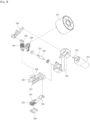
- FIG. 1 is a perspective view of an auto strapping packaging tool having a clamp fixing apparatus according to one embodiment of the present invention
- FIG. 2 is a plan view of FIG. 1 when viewed from above
- FIG. 3 is an exploded perspective view of FIG. 1
- the auto strapping packaging tool including the clamp fixing apparatus may include a body assembly 100, a tension module 200, a welding module 300, a hooking part 400, a lever unit 500, and the like.
- a tensile force having a predetermined magnitude is applied to a plastic band by the tension module 200 after the packaging plastic band is disposed to wrap around goods.
- the plastic band receives friction heat caused by vibration in a state in which the plastic band is pressed by the welding module 300, and portions of the plastic band, which overlaps itself in two layers, are locally melted so that the portions are bonded.
- the plastic band may be formed of a polypropylene (PP) material, a polyethylene terephthalate (PET) material, or the like.
- the body assembly 100 may include a part of a body housing.
- the body assembly 100 allows internal components, for example, the tension module 200, to be stably disposed in the body housing.
- the hooking part 400 and the like are installed and provide uses and functions.
- the body assembly 100 is formed in a shape designed in advance to provide systematic relationships between the internal components and smooth implementation of the functions therethrough.
- the tension module 200 is partially coupled to the body assembly 100 and provides a tensile force to the plastic band through a first motor 210, a feed wheel part 220 which is rotated about a first shaft a1 by the first motor 210, and a clamp part 230 which is disposed around the feed wheel part 220 and rotated about a second shaft a2.
- the tension module 200 receives a rotational force provided by the first motor 210 to wrap and pull one end of the plastic band.
- the tension module 200 may provide the tensile force to the plastic band through the operation of pooling the plastic band in a strapping process.
- the tension module 200 may include the first shaft a1 which is disposed at a central portion and axially rotated, a worm gear unit which is a gear assembly disposed on an outer circumference of the first shaft a1, engaged with the first shaft a1, and rotated at a reduced speed, and the like.
- the tension module 200 may further include the feed wheel part 220 which is coupled to an outer circumferential surface of the worm gear unit and rotated therewith and wraps and pulls the plastic band using a friction force caused by pressurization, and the like.
- the feed wheel part 220 has a cylindrical shape, and a knurling portion is formed on an outer circumferential surface thereof.
- first motor 210 is disposed in a rear portion in the tension module 200.
- a first driving shaft of the first motor 210 is disposed to be parallel to the first shaft a1.
- a spur gear which transmits a rotational force to the first shaft a1, is coupled to the first driving shaft.
- first power generated by the first motor 210 may be transmitted to the feed wheel part 220 through the first driving shaft, the first shaft a1, and the worm gear unit.
- the tension module 200 may further include an annular ring portion 240 which is coupled to the feed wheel part 220 and is rotated about the first shaft a1, and on which a first tooth 241 is formed on one part thereof, and a protruding piece 242 is formed on another part thereof in a radial direction.
- the annular ring portion 240 has a ring shape and reciprocates within a predetermined angular range by a connecting piece 610 when coupled to the feed wheel part 220.
- the clamp part 230 has substantially an "L" shape and rotates about the second shaft a2.
- a curved knurling portion may be formed on the clamp part 230 to correspond to the knurling portion.
- a groove, in which the protruding piece 242 is accommodated and coupled thereto, is formed in an end of the clamp part 230.
- the clamp part 230 is rotated about the second shaft a2 according to rotation due to the annular ring portion 240.
- the clamp part 230 is separated from the feed wheel part 220, and the plastic band may be inserted into a gap therebetween.
- the pulling operation is released so that the lever unit 500 moves in an opposite direction, the clamp part 230 becomes close to the feed wheel part 220.
- FIG. 4 is an exploded perspective view illustrating the lever unit of FIG. 1
- FIG. 5 is an exploded perspective view illustrating the welding module of FIG. 1
- the welding module 300 includes a second motor 311 and a third motor 351 and provides a friction force to the plastic band to which the tensile force is applied by the tension module 200.
- the auto strapping packaging tool includes the first motor 210 to the third motor 351. In this case, rotating speeds, rotating times, and the like of the first motor 210 to the third motor 351 are controlled by a control part (not shown).
- the first motor 210 to the third motor 351 may be electric motors operated by power provided from the outside (or a power source such as an internal battery).
- the welding module 300 is disposed at one side of the tension module 200 and provides friction heat to bond the plastic band disposed in two layers. Meanwhile, although units, components, and the like included in the welding module 300 are not illustrated in the drawings, all or some thereof may be installed, held, and fixed using the above-described holding elements.
- the welding module 300 may include a friction providing unit which is disposed in the body assembly 100 and linearly reciprocates due to second power generated by the second motor 311 to provide the friction force to the plastic band to which the tensile force is applied by the tension module 200 and an opening and closing unit having one end coupled to the friction providing unit, and performing link movement caused by third power generated by the third motor 351 to provide vertical movement for the friction providing unit and open or close the friction providing unit through an operation according to axial rotation.
- a friction providing unit which is disposed in the body assembly 100 and linearly reciprocates due to second power generated by the second motor 311 to provide the friction force to the plastic band to which the tensile force is applied by the tension module 200 and an opening and closing unit having one end coupled to the friction providing unit, and performing link movement caused by third power generated by the third motor 351 to provide vertical movement for the friction providing unit and open or close the friction providing unit through an operation according to axial rotation.
- first motor 210 to the third motor 351 are disposed in modules, each of the tension module 200 and the welding module 300 are formed in units of modules, and thus, driving of the first motor 210 to the third motor 351 may be individually controlled.
- first motor 210 to the third motor 351 are disposed in rear portions in the modules, and thus the weight of the auto strapping packaging tool may be easily distributed. This is a difference from an inner layout of a conventional auto strapping packaging tool and may improve user convenience. That is, since the weight applied to the auto strapping packaging tool may be effectively distributed, even when the user performs packaging work for a long time, there is no strain on a wrist joint and the like.
- a bevel gear is coupled to a second driving shaft of the second motor 311.
- the welding module 300 may further include a spur gear part 330 disposed between the second motor 311 and the friction providing unit to transmit the second power therebetween.
- the spur gear part 330 may include 1) a first connecting shaft on which the bevel gear and the spur gear are coupled to an outer circumferential surface and which is perpendicularly engaged with the second driving shaft by the bevel gear, and 2) a second connecting shaft which is disposed to be parallel to the first connecting shaft and to which a spur gear engaged with a spur gear of the first connecting shaft is coupled so that the second connecting shaft is driven by a rotational force of the first connecting shaft.
- the friction providing unit may include the second motor 311, a second driven shaft 321, an inner gripper part 323, an outer gripper part 326, a lower gripper part 329, and the like.
- the second driven shaft 321 is driven by the second power, and a second eccentric element 322 is formed on an outer circumferential surface of the second driven shaft 321. Meanwhile, a spur gear engaged with the spur gear part 330 is coupled to one end of the second driven shaft 321.
- a half ring piece 324 formed on one end of the inner gripper part 323 is held on the second driven shaft 321 so that the inner gripper part 323 linearly and slidably reciprocates by a cam movement according to axial rotation of the second driven shaft 321, and guide protrusions 325 are formed on both side surfaces of the inner gripper part 323.
- the inner gripper part 323 is moved downward by the opening and closing unit and linearly reciprocates within a predetermined stroke due to the second power of the second motor 311. That is, the inner gripper part 323 vibrates.
- a knurling plate may be formed on a lower surface of the inner gripper part 323. Grooves are repeatedly formed in a lateral or diagonal direction to have a predetermined pattern in the knurling plate.
- the outer gripper part 326 is axially rotatably coupled to the second driven shaft 321, and the inner gripper part 323 may be accommodated in the outer gripper part 326 and may slidably enter or exit the outer gripper part 326.
- the outer gripper part 326 may further include protrusion grooves 327 formed in inner side surfaces thereof to correspond to the guide protrusions 325 and a coupling hole 328 on which a part of an upper surface is open, and to which an end portion of a connecting rod part 356 is axially rotatably coupled.
- the lower gripper part 329 is disposed at a position facing a lower side of the inner gripper part 323. Meanwhile, a knurling plate is also formed on an upper surface of the lower gripper part 329.
- the welding module 300 may further include a cutting unit (not shown) which is moved downward in conjunction with downward movement of the opening and closing unit to cut the plastic band.
- the opening and closing unit is coupled to an upper portion of the friction providing unit, and when the third power is transmitted thereto, the opening and closing unit provides vertical movement for the friction providing unit to open or close the friction providing unit through the operation according to axial rotation.
- the opening and closing unit may include the third motor 351, an eccentric driving shaft 352, a link part 354, a connecting rod part 356, an elastic member 358, an opening and closing unit holding element 359, and the like.
- the eccentric driving shaft 352 is disposed at the other end of the third motor 351 to be eccentric to one side.
- One end of the link part 354 is coupled to an end portion of the eccentric driving shaft 352.
- the link part 354 performs cam movement according to axial rotation of the eccentric driving shaft 352.
- One end of the connecting rod part 356 is coupled to the link part 354, and the other end thereof is coupled to the friction providing unit to vertically move the friction providing unit according to rotation of the eccentric driving shaft 352.
- the elastic member 358 which buffers vibration generated by linear reciprocating movement of the friction providing unit, may be disposed on an outer circumferential surface of the connecting rod part 356.
- the third power generated by the third motor 351 is finally transmitted to the friction providing unit through the eccentric driving shaft 352, the link part 354, and the connecting rod part 356.
- the hooking part 400 is composed of a first hooking element 410 axially rotatably disposed on the body assembly 100 and a second hooking element 420 fixedly disposed on the body assembly 100.
- the first hooking element 410 has a cylindrical shape, and a plurality of hooking steps disposed to be spaced apart from each other in one direction are formed on an outer circumferential surface of the first hooking element 410.
- the first hooking element 410 may include a pressing button bar 411 which is pressed by the user and coupled to the first hooking element 410 so that the first hooking element 410 is axially rotated.
- the first hooking element 410 may include a torsion spring that is compressed in the direction of axial rotation when the pressing button bar 411 is pressed.
- the second hooking element 420 is fixedly disposed in the body assembly 100. Specifically, the second hooking element 420 has a cylindrical shape, and a plurality of hooking steps disposed to be spaced apart from each other in one direction are formed on an outer circumferential surface of the second hooking element 420. A shape of the second hooking element 420 may be the same as or similar to that of the first hooking element 410.
- the lever unit 500 is axially rotatably coupled to the body assembly 100, and when the pulling operation is applied to the lever unit 500 by the user, the lever unit 500 is hooked on the first hooking element 410 so that a position thereof is fixed, and the lever unit 500 is switched to an open mode. Meanwhile, in the process in which the lever unit 500 is switched to the open mode, the clamp part 230 axially rotates around the feed wheel part 220 to be opened. In the open mode, a hooking step of a first hooking piece 520 is hooked on the first hooking element 410 so that a lever body 510 is fixed at that position. In this case, a lever shaft 531 is also rotated by the same angle to rotate the annular ring portion 240 through the connecting piece 610. As a result, the clamp part 230 is separated from the feed wheel part 220, fixed in that state, and opened.
- the lever unit 500 may include the lever body 510, the first hooking piece 520, an extension hooking member 530, and the like.
- a handle is formed on one end of the lever body 510, and a shaft hole 511 is formed in the other end thereof so that the lever body 510 is axially rotatable.
- a coil spring is disposed in the lever body 510. The lever body 510 is rotated by a predetermined angle by the pulling operation of the user, and when the pulling operation is released in that state, the lever body 510 is returned to an original position due to an elastic restoring force of the coil spring.
- the first hooking piece 520 extends outward from the lever body 510, and a hooking step is formed on an end portion of the first hooking piece 520.
- the extension hooking member 530 is coupled to the other end of the lever body 510, and when the lever unit 500 is switched to the open mode, the extension hooking member 530 is released from hooking on the second hooking element 420. Conversely, the lever body 510 is switched to a closed mode from the open mode, the extension hooking member 530 is hooked on and coupled to the second hooking element 420. The extension hooking member 530 is rotated by the same angle in conjunction with rotation of the lever body 510.
- the extension hooking member 530 may include a member body, the lever shaft 531 which is formed on one side surface of the member body and passes through and is coupled to the shaft hole 511, and a second hooking piece 532 which extends outward from the member body and in which a hooking step is formed on an end portion thereof.
- the connecting piece 610 having one end coupled to an end portion of the lever shaft 531 and the other end in which a second tooth engaged with the first tooth 241 is formed, may be disposed between the lever unit 500 and the tension module 200.
- the connecting piece 610 is rotated by a predetermined angle to correspond to rotation of the lever shaft 531.
- the annular ring portion 240 engaged with the connecting piece 610 is also rotated.
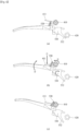
- FIGS. 6A to 6C are a set of views showing a process in which the clamp part is fixed by an operation of the hooking part and the lever unit of FIG. 1
- FIGS. 7A and 7B are a set of views showing rotation of the clamp part in the process of FIG. 6 .
- the second hooking piece 532 of the lever unit 500 is hooked on the second hooking element 420.
- the clamp part 230 is close to (or partially in contact with) the feed wheel part 220 as in FIG. 7B . This is referred to as the closed mode.
- a process in which the plastic band is inserted into the tension module 200 is performed for strapping. Referring to FIGS.
- the user presses the pressing button bar 411 to rotate the first hooking element 410 to a predetermined angle. Then, the user applies the pulling operation to the lever body 510 so that the end portion, that is, the hooking step, of the first hooking piece 520 is hooked on and coupled to the first hooking element 410.
- the lever body 510 maintains the hooked state.
- the extension hooking member 530 is rotated in conjunction with the pulling operation for the lever body 510, and as a result, the second hooking piece 532 is released from hooking on the second hooking element 420.
- the clamp part 230 rotates about the second shaft a2 in conjunction with the pulling operation for the lever body 510.
- the clamp part 230 is separated and moved away from the feed wheel part 220, and the clamp part 230 is fixed in that state. That is, the closed mode is switched to the open mode.
- the plastic band may be inserted into the tension module 200.
- the connecting piece 610 rotates the annular ring portion 240 engaged therewith, and the annular ring portion 240 rotates the clamp part 230 using the protruding piece 242.
- the user presses the first hooking piece 520 in a downward direction.
- the first hooking element 410 is rotated by a predetermined angle, and the lever unit 500 is returned to an original position by an elastic restoring force of the coil spring.
- the connecting piece 610 rotates the annular ring portion 240 in a reverse direction.
- the clamp part 230 becomes close to (or is partially in contact with) the feed wheel part 220.
- tension module 200 and the welding module 300 are formed in units of modules, driving thereof is individually controlled. That is, the tension module 200 and the welding module 300 are completely separated and independently operated. Therefore, the productivity is improved, and assembly efficiency is maximized.
- the plastic band receives a tensile force having a magnitude preset by the first power generated by the first motor 210. Accordingly, the tensile force providing process is completed. Then, the welding module 300 is operated for welding. A welding process is started by an operation of the opening and closing unit. In this process, when the connecting rod part 356 is moved downward by the third power generated by the third motor 351, the friction providing unit in the open state is switched to the closed state. Then, the friction providing unit linearly reciprocates due to the second power generated by the second motor 311 to provide a friction force to the plastic band provided through the tension module 200. As a result, the plastic band, which overlaps itself in two layers, disposed between the inner gripper part 323 and the lower gripper part 329 is locally melted and two layers are bonded.
- an open mode and a closed mode for a clamp can be switched by a simple manipulation of a user.
- the open mode and the closed mode there are the open mode and the closed mode.
- switching between the modes can be performed by the simple manipulation of the user.
- the clamp can be stably fixed in the open mode.
Landscapes
- Engineering & Computer Science (AREA)
- Mechanical Engineering (AREA)
- Basic Packing Technique (AREA)
Claims (7)
- Outil d'emballage par cerclage automatique ayant un appareil de fixation par pince, comprenant:un ensemble corps (100);un module de tension (200) qui est en partie accouplé à l'ensemble corps (100) et fournit une force de traction à une bande plastique à l'aide d'un premier moteur (210), une partie roue d'alimentation (220) que fait tourner le premier moteur (210) autour d'un premier arbre (a1) et une partie pince (230) disposée autour de la partie roue d'alimentation (220) et qui tourne autour d'un second arbre (a2);un module de soudage (300), qui comprend un deuxième moteur (311) et un troisième moteur (351), conçus pour fournir une force de friction à la bande en plastique à laquelle la force de traction est appliquée par le module de tension (200);une partie d'accrochage (400) pourvue d'un premier élément d'accrochage (410) disposé axialement en rotation dans l'ensemble corps (100) et d'un second élément d'accrochage (420) disposé à demeure dans l'ensemble corps (100); etune unité de levier (500) qui est accouplée axialement en rotation à l'ensemble corps (100) et commutée sur un mode ouvert tandis que sa position est fixée par le fait qu'elle est accrochée sur le premier élément d'accrochage (410) lorsqu'une opération de tirage d'un utilisateur y est appliquée,dans lequel dans le mode ouvert, la partie pince (230) est séparée et éloignée par rapport à la partie roue d'alimentation (220),dans lequel le module de soudage (300) comprend en outre:une unité d'apport de friction qui est disposée dans l'ensemble corps (100) et aminée linéairement d'un mouvement alternatif en raison d'une seconde puissance générée par le deuxième moteur (311) pour fournir la force de friction à la bande de plastique à laquelle la force de traction est appliquée par le module de tension (200); etune unité d'ouverture et de fermeture qui a une extrémité accouplée à l'unité d'apport de friction, effectue un mouvement de liaison en raison de la troisième puissance générée par le troisième moteur (351) pour fournir un mouvement vertical pour l'unité d'apport de friction, et ouvre ou ferme l'unité d'apport de friction par le biais d'une opération selon la rotation axiale,dans lequel le premier moteur (210), le deuxième moteur (311) et le troisième moteur (351) sont disposés dans des parties proches dans les modules (200, 300).
- Outil d'emballage par cerclage automatique selon la revendication 1, dans lequel dans un processus dans lequel l'unité de levier (500) est commutée sur le mode ouvert, la partie pince (230) est tournée axialement autour de la partie roue d'alimentation (220) pour être ouverte.
- Outil d'emballage par cerclage automatique selon la revendication 1 ou 2, dans lequel l'unité de levier (500) comprend:un corps de levier (510) ayant un manche formé à son extrémité, et un trou d'arbre (511) formé dans l'autre extrémité pour qu'il puisse tourner axialement;une première pièce d'accrochage (520) qui s'étend vers l'extérieur à partir du corps de levier (500) et a un palier d'accrochage formé sur sa partie d'extrémité; etun élément d'accrochage d'extension (530) qui est accouplé à l'autre extrémité du corps de levier (510) et n'est plus accroché sur le second élément d'accrochage (420) lorsque l'unité de levier (500) est commutée sur le mode ouvert.
- Outil d'emballage par cerclage automatique selon l'une quelconque des revendications 1 à 3, dans lequel le module de tension (200) comprend en outre une partie de bague annulaire (240) qui est accouplée à la partie roue d'alimentation (220) pour qu'elle tourne autour du premier arbre (a1) et a une première dent (241) formée sur une partie de celle-ci et une pièce en saillie (242) formée sur une autre partie de celle-ci dans une direction radiale.
- Outil d'emballage par cerclage automatique selon la revendication 4, dans lequel une pièce de liaison (610) ayant une extrémité reliée à une partie d'extrémité d'un arbre de levier (531) et l'autre extrémité dans laquelle est formée une seconde dent engrenée avec la première dent (241) est disposée entre l'unité de levier et le module de tension (200).
- Outil d'emballage par cerclage automatique selon l'une quelconque des revendications 1 à 5, dans lequel le premier élément d'accrochage (410) comprend une barre de bouton de pression (411) enfoncée par l'utilisateur et accouplée au premier élément d'accrochage (410) de sorte que le premier élément d'accrochage (410) tourne axialement.
- Outil d'emballage par cerclage automatique selon l'une quelconque des revendications 1 à 6, dans lequel:le premier élément d'accrochage (410) présente une forme cylindrique; etune pluralité de paliers d'accrochage disposés pour être éloignés les uns des autres dans une direction sont formés sur une surface circonférentielle extérieure du premier élément d'accrochage (410).
Applications Claiming Priority (1)
| Application Number | Priority Date | Filing Date | Title |
|---|---|---|---|
| KR1020210006578A KR102315941B1 (ko) | 2021-01-18 | 2021-01-18 | 클램프 고정 장치를 갖는 자동 스트래핑 포장용 공구 |
Publications (2)
| Publication Number | Publication Date |
|---|---|
| EP4029794A1 EP4029794A1 (fr) | 2022-07-20 |
| EP4029794B1 true EP4029794B1 (fr) | 2023-07-19 |
Family
ID=77774828
Family Applications (1)
| Application Number | Title | Priority Date | Filing Date |
|---|---|---|---|
| EP21196922.5A Active EP4029794B1 (fr) | 2021-01-18 | 2021-09-15 | Outil d'emballage à cerclage automatique doté d'un appareil de fixation par pince |
Country Status (3)
| Country | Link |
|---|---|
| US (1) | US20220227508A1 (fr) |
| EP (1) | EP4029794B1 (fr) |
| KR (1) | KR102315941B1 (fr) |
Families Citing this family (5)
| Publication number | Priority date | Publication date | Assignee | Title |
|---|---|---|---|---|
| US11174051B2 (en) | 2019-02-15 | 2021-11-16 | Samuel, Son & Co. (Usa) Inc. | Hand held strapping tool |
| US12397943B2 (en) | 2022-11-29 | 2025-08-26 | Samuel, Son & Co. (Usa) Inc. | Handheld strapping device |
| KR102619916B1 (ko) * | 2023-06-27 | 2023-12-29 | 장근철 | 사용 편의성이 향상된 자동 스트래핑 장치 |
| KR102619914B1 (ko) * | 2023-06-27 | 2023-12-29 | 장근철 | 장착 용이성을 향상시킨 자동 스트래핑 장치 |
| CN121866207A (zh) * | 2023-09-19 | 2026-04-14 | 信诺工业集团有限责任公司 | 具有可线性移动的张紧与焊接板的捆扎装置 |
Family Cites Families (11)
| Publication number | Priority date | Publication date | Assignee | Title |
|---|---|---|---|---|
| US3586572A (en) * | 1969-02-20 | 1971-06-22 | Signode Corp | Electrically controlled handtool for friction-fusing nonmetallic strap |
| KR960009771B1 (ko) * | 1994-06-07 | 1996-07-24 | 최학구 | 의복단추 생크(shank)부의 실감침 장치 |
| DE59907002D1 (de) * | 1998-10-29 | 2003-10-23 | Orgapack Gmbh Dietikon | Umreifungsgerät |
| US7556129B2 (en) * | 2005-12-14 | 2009-07-07 | Illinois Tool Works, Inc, | Motor brake |
| US9174752B2 (en) * | 2008-04-23 | 2015-11-03 | Signode Industrial Group Llc | Strapping device with a gear system device |
| CN102026875B (zh) | 2008-04-23 | 2016-01-20 | 信诺国际Ip控股有限责任公司 | 带有拉紧装置的捆扎设备 |
| DE202011109483U1 (de) * | 2011-12-23 | 2012-02-01 | Fromm Holding Ag | Pneumatisch betätigtes Umreifungsgerät |
| EP2711301B1 (fr) * | 2012-09-24 | 2016-11-02 | S.I.A.T. SOCIETA' INTERNAZIONALE APPLICAZIONI TECNICHE S.p.A. | Dispositif de cerclage mobile |
| CH712984A2 (de) | 2016-09-18 | 2018-03-29 | Signode Ind Group Llc | Umreifungsvorrichtung zur Umreifung von Packgut mit einem Umreifungsband. |
| IT201900006286A1 (it) * | 2019-04-24 | 2020-10-24 | Itatools S R L | Reggiatrice |
| KR20210006578A (ko) | 2019-07-09 | 2021-01-19 | 주식회사 디딤소프트 | 딥러닝으로 구축된 이미지검색 시스템의 음성검색 기술 |
-
2021
- 2021-01-18 KR KR1020210006578A patent/KR102315941B1/ko not_active Expired - Fee Related
- 2021-09-15 US US17/475,340 patent/US20220227508A1/en not_active Abandoned
- 2021-09-15 EP EP21196922.5A patent/EP4029794B1/fr active Active
Also Published As
| Publication number | Publication date |
|---|---|
| KR102315941B1 (ko) | 2021-10-22 |
| EP4029794A1 (fr) | 2022-07-20 |
| US20220227508A1 (en) | 2022-07-21 |
Similar Documents
| Publication | Publication Date | Title |
|---|---|---|
| EP4029794B1 (fr) | Outil d'emballage à cerclage automatique doté d'un appareil de fixation par pince | |
| EP4029795B1 (fr) | Structure du module interne d'un outil d'emballage à cerclage automatique | |
| EP1666359B1 (fr) | Dispositif de cerclage à deux moteurs | |
| CN102026872B (zh) | 带有传动装置的捆扎设备 | |
| JP6329151B2 (ja) | バンド掛け装置 | |
| EP2178762B1 (fr) | Outil à sangler composé de deux pièces | |
| JP5015979B2 (ja) | バンド掛機用加振アンビル付き溶着ヘッド | |
| CN104169172B (zh) | 捆扎机 | |
| JP2011518086A (ja) | 携帯型バンド掛け装置 | |
| JP2011518088A (ja) | テンショナを有するバンド掛け装置 | |
| US5690023A (en) | Tensioning and sealing apparatus for strapping an object with a band | |
| US20250083847A1 (en) | Strapping tool | |
| WO2024050278A1 (fr) | Dispositif de cerclage doté d'un ensemble de tension et de soudage combiné | |
| US12097663B2 (en) | Strap welding system and method | |
| CA2543819C (fr) | Dispositif de banderolage a double moteur | |
| WO2026080295A1 (fr) | Dispositif de cerclage doté d'une plaque de tension et de fermeture mobile linéairement | |
| WO2025064295A1 (fr) | Dispositif de cerclage doté d'une plaque de tension et de soudage mobile linéairement | |
| TW202523421A (zh) | 具有組合式張緊焊接組合件的捆紮裝置 | |
| WO2026043710A1 (fr) | Dispositif de cerclage doté d'un sous-ensemble combiné de tension et d'étanchéité | |
| WO2026054963A1 (fr) | Dispositif de cerclage doté d'un sous-ensemble combiné de tension et de fermeture | |
| TW202612986A (zh) | 動力手持打包機結構 | |
| TW202602742A (zh) | 捆紮工具 | |
| WO2023235696A1 (fr) | Dispositif de cerclage portatif et son procédé de fonctionnement | |
| CN121568876A (zh) | 包括超声波封锁器的手持式捆扎工具 | |
| MXPA99002923A (en) | Tool operated with level to weld strap and method for e |
Legal Events
| Date | Code | Title | Description |
|---|---|---|---|
| PUAI | Public reference made under article 153(3) epc to a published international application that has entered the european phase |
Free format text: ORIGINAL CODE: 0009012 |
|
| STAA | Information on the status of an ep patent application or granted ep patent |
Free format text: STATUS: EXAMINATION IS IN PROGRESS |
|
| 17P | Request for examination filed |
Effective date: 20210915 |
|
| AK | Designated contracting states |
Kind code of ref document: A1 Designated state(s): AL AT BE BG CH CY CZ DE DK EE ES FI FR GB GR HR HU IE IS IT LI LT LU LV MC MK MT NL NO PL PT RO RS SE SI SK SM TR |
|
| GRAP | Despatch of communication of intention to grant a patent |
Free format text: ORIGINAL CODE: EPIDOSNIGR1 |
|
| STAA | Information on the status of an ep patent application or granted ep patent |
Free format text: STATUS: GRANT OF PATENT IS INTENDED |
|
| INTG | Intention to grant announced |
Effective date: 20230216 |
|
| GRAS | Grant fee paid |
Free format text: ORIGINAL CODE: EPIDOSNIGR3 |
|
| GRAA | (expected) grant |
Free format text: ORIGINAL CODE: 0009210 |
|
| STAA | Information on the status of an ep patent application or granted ep patent |
Free format text: STATUS: THE PATENT HAS BEEN GRANTED |
|
| AK | Designated contracting states |
Kind code of ref document: B1 Designated state(s): AL AT BE BG CH CY CZ DE DK EE ES FI FR GB GR HR HU IE IS IT LI LT LU LV MC MK MT NL NO PL PT RO RS SE SI SK SM TR |
|
| REG | Reference to a national code |
Ref country code: GB Ref legal event code: FG4D |
|
| REG | Reference to a national code |
Ref country code: CH Ref legal event code: EP |
|
| REG | Reference to a national code |
Ref country code: DE Ref legal event code: R096 Ref document number: 602021003575 Country of ref document: DE |
|
| REG | Reference to a national code |
Ref country code: IE Ref legal event code: FG4D |
|
| REG | Reference to a national code |
Ref country code: LT Ref legal event code: MG9D |
|
| REG | Reference to a national code |
Ref country code: NL Ref legal event code: MP Effective date: 20230719 |
|
| PGFP | Annual fee paid to national office [announced via postgrant information from national office to epo] |
Ref country code: FR Payment date: 20230929 Year of fee payment: 3 |
|
| REG | Reference to a national code |
Ref country code: AT Ref legal event code: MK05 Ref document number: 1589244 Country of ref document: AT Kind code of ref document: T Effective date: 20230719 |
|
| PG25 | Lapsed in a contracting state [announced via postgrant information from national office to epo] |
Ref country code: NL Free format text: LAPSE BECAUSE OF FAILURE TO SUBMIT A TRANSLATION OF THE DESCRIPTION OR TO PAY THE FEE WITHIN THE PRESCRIBED TIME-LIMIT Effective date: 20230719 |
|
| PG25 | Lapsed in a contracting state [announced via postgrant information from national office to epo] |
Ref country code: GR Free format text: LAPSE BECAUSE OF FAILURE TO SUBMIT A TRANSLATION OF THE DESCRIPTION OR TO PAY THE FEE WITHIN THE PRESCRIBED TIME-LIMIT Effective date: 20231020 |
|
| PG25 | Lapsed in a contracting state [announced via postgrant information from national office to epo] |
Ref country code: IS Free format text: LAPSE BECAUSE OF FAILURE TO SUBMIT A TRANSLATION OF THE DESCRIPTION OR TO PAY THE FEE WITHIN THE PRESCRIBED TIME-LIMIT Effective date: 20231119 |
|
| PG25 | Lapsed in a contracting state [announced via postgrant information from national office to epo] |
Ref country code: SE Free format text: LAPSE BECAUSE OF FAILURE TO SUBMIT A TRANSLATION OF THE DESCRIPTION OR TO PAY THE FEE WITHIN THE PRESCRIBED TIME-LIMIT Effective date: 20230719 Ref country code: RS Free format text: LAPSE BECAUSE OF FAILURE TO SUBMIT A TRANSLATION OF THE DESCRIPTION OR TO PAY THE FEE WITHIN THE PRESCRIBED TIME-LIMIT Effective date: 20230719 Ref country code: PT Free format text: LAPSE BECAUSE OF FAILURE TO SUBMIT A TRANSLATION OF THE DESCRIPTION OR TO PAY THE FEE WITHIN THE PRESCRIBED TIME-LIMIT Effective date: 20231120 Ref country code: NO Free format text: LAPSE BECAUSE OF FAILURE TO SUBMIT A TRANSLATION OF THE DESCRIPTION OR TO PAY THE FEE WITHIN THE PRESCRIBED TIME-LIMIT Effective date: 20231019 Ref country code: LV Free format text: LAPSE BECAUSE OF FAILURE TO SUBMIT A TRANSLATION OF THE DESCRIPTION OR TO PAY THE FEE WITHIN THE PRESCRIBED TIME-LIMIT Effective date: 20230719 Ref country code: LT Free format text: LAPSE BECAUSE OF FAILURE TO SUBMIT A TRANSLATION OF THE DESCRIPTION OR TO PAY THE FEE WITHIN THE PRESCRIBED TIME-LIMIT Effective date: 20230719 Ref country code: IS Free format text: LAPSE BECAUSE OF FAILURE TO SUBMIT A TRANSLATION OF THE DESCRIPTION OR TO PAY THE FEE WITHIN THE PRESCRIBED TIME-LIMIT Effective date: 20231119 Ref country code: HR Free format text: LAPSE BECAUSE OF FAILURE TO SUBMIT A TRANSLATION OF THE DESCRIPTION OR TO PAY THE FEE WITHIN THE PRESCRIBED TIME-LIMIT Effective date: 20230719 Ref country code: GR Free format text: LAPSE BECAUSE OF FAILURE TO SUBMIT A TRANSLATION OF THE DESCRIPTION OR TO PAY THE FEE WITHIN THE PRESCRIBED TIME-LIMIT Effective date: 20231020 Ref country code: FI Free format text: LAPSE BECAUSE OF FAILURE TO SUBMIT A TRANSLATION OF THE DESCRIPTION OR TO PAY THE FEE WITHIN THE PRESCRIBED TIME-LIMIT Effective date: 20230719 Ref country code: AT Free format text: LAPSE BECAUSE OF FAILURE TO SUBMIT A TRANSLATION OF THE DESCRIPTION OR TO PAY THE FEE WITHIN THE PRESCRIBED TIME-LIMIT Effective date: 20230719 |
|
| PGFP | Annual fee paid to national office [announced via postgrant information from national office to epo] |
Ref country code: DE Payment date: 20231026 Year of fee payment: 3 |
|
| PG25 | Lapsed in a contracting state [announced via postgrant information from national office to epo] |
Ref country code: PL Free format text: LAPSE BECAUSE OF FAILURE TO SUBMIT A TRANSLATION OF THE DESCRIPTION OR TO PAY THE FEE WITHIN THE PRESCRIBED TIME-LIMIT Effective date: 20230719 |
|
| REG | Reference to a national code |
Ref country code: DE Ref legal event code: R097 Ref document number: 602021003575 Country of ref document: DE |
|
| PG25 | Lapsed in a contracting state [announced via postgrant information from national office to epo] |
Ref country code: ES Free format text: LAPSE BECAUSE OF FAILURE TO SUBMIT A TRANSLATION OF THE DESCRIPTION OR TO PAY THE FEE WITHIN THE PRESCRIBED TIME-LIMIT Effective date: 20230719 |
|
| PG25 | Lapsed in a contracting state [announced via postgrant information from national office to epo] |
Ref country code: SM Free format text: LAPSE BECAUSE OF FAILURE TO SUBMIT A TRANSLATION OF THE DESCRIPTION OR TO PAY THE FEE WITHIN THE PRESCRIBED TIME-LIMIT Effective date: 20230719 Ref country code: RO Free format text: LAPSE BECAUSE OF FAILURE TO SUBMIT A TRANSLATION OF THE DESCRIPTION OR TO PAY THE FEE WITHIN THE PRESCRIBED TIME-LIMIT Effective date: 20230719 Ref country code: ES Free format text: LAPSE BECAUSE OF FAILURE TO SUBMIT A TRANSLATION OF THE DESCRIPTION OR TO PAY THE FEE WITHIN THE PRESCRIBED TIME-LIMIT Effective date: 20230719 Ref country code: EE Free format text: LAPSE BECAUSE OF FAILURE TO SUBMIT A TRANSLATION OF THE DESCRIPTION OR TO PAY THE FEE WITHIN THE PRESCRIBED TIME-LIMIT Effective date: 20230719 Ref country code: DK Free format text: LAPSE BECAUSE OF FAILURE TO SUBMIT A TRANSLATION OF THE DESCRIPTION OR TO PAY THE FEE WITHIN THE PRESCRIBED TIME-LIMIT Effective date: 20230719 Ref country code: CZ Free format text: LAPSE BECAUSE OF FAILURE TO SUBMIT A TRANSLATION OF THE DESCRIPTION OR TO PAY THE FEE WITHIN THE PRESCRIBED TIME-LIMIT Effective date: 20230719 Ref country code: SK Free format text: LAPSE BECAUSE OF FAILURE TO SUBMIT A TRANSLATION OF THE DESCRIPTION OR TO PAY THE FEE WITHIN THE PRESCRIBED TIME-LIMIT Effective date: 20230719 |
|
| PG25 | Lapsed in a contracting state [announced via postgrant information from national office to epo] |
Ref country code: LU Free format text: LAPSE BECAUSE OF NON-PAYMENT OF DUE FEES Effective date: 20230915 |
|
| PLBE | No opposition filed within time limit |
Free format text: ORIGINAL CODE: 0009261 |
|
| STAA | Information on the status of an ep patent application or granted ep patent |
Free format text: STATUS: NO OPPOSITION FILED WITHIN TIME LIMIT |
|
| REG | Reference to a national code |
Ref country code: BE Ref legal event code: MM Effective date: 20230930 |
|
| PG25 | Lapsed in a contracting state [announced via postgrant information from national office to epo] |
Ref country code: LU Free format text: LAPSE BECAUSE OF NON-PAYMENT OF DUE FEES Effective date: 20230915 Ref country code: IT Free format text: LAPSE BECAUSE OF FAILURE TO SUBMIT A TRANSLATION OF THE DESCRIPTION OR TO PAY THE FEE WITHIN THE PRESCRIBED TIME-LIMIT Effective date: 20230719 Ref country code: MC Free format text: LAPSE BECAUSE OF FAILURE TO SUBMIT A TRANSLATION OF THE DESCRIPTION OR TO PAY THE FEE WITHIN THE PRESCRIBED TIME-LIMIT Effective date: 20230719 |
|
| 26N | No opposition filed |
Effective date: 20240422 |
|
| REG | Reference to a national code |
Ref country code: IE Ref legal event code: MM4A |
|
| PG25 | Lapsed in a contracting state [announced via postgrant information from national office to epo] |
Ref country code: IE Free format text: LAPSE BECAUSE OF NON-PAYMENT OF DUE FEES Effective date: 20230915 |
|
| PG25 | Lapsed in a contracting state [announced via postgrant information from national office to epo] |
Ref country code: IE Free format text: LAPSE BECAUSE OF NON-PAYMENT OF DUE FEES Effective date: 20230915 Ref country code: SI Free format text: LAPSE BECAUSE OF FAILURE TO SUBMIT A TRANSLATION OF THE DESCRIPTION OR TO PAY THE FEE WITHIN THE PRESCRIBED TIME-LIMIT Effective date: 20230719 |
|
| PG25 | Lapsed in a contracting state [announced via postgrant information from national office to epo] |
Ref country code: BE Free format text: LAPSE BECAUSE OF NON-PAYMENT OF DUE FEES Effective date: 20230930 |
|
| PG25 | Lapsed in a contracting state [announced via postgrant information from national office to epo] |
Ref country code: BG Free format text: LAPSE BECAUSE OF FAILURE TO SUBMIT A TRANSLATION OF THE DESCRIPTION OR TO PAY THE FEE WITHIN THE PRESCRIBED TIME-LIMIT Effective date: 20230719 |
|
| PG25 | Lapsed in a contracting state [announced via postgrant information from national office to epo] |
Ref country code: BG Free format text: LAPSE BECAUSE OF FAILURE TO SUBMIT A TRANSLATION OF THE DESCRIPTION OR TO PAY THE FEE WITHIN THE PRESCRIBED TIME-LIMIT Effective date: 20230719 |
|
| PGFP | Annual fee paid to national office [announced via postgrant information from national office to epo] |
Ref country code: CH Payment date: 20241001 Year of fee payment: 4 |
|
| REG | Reference to a national code |
Ref country code: DE Ref legal event code: R119 Ref document number: 602021003575 Country of ref document: DE |
|
| PG25 | Lapsed in a contracting state [announced via postgrant information from national office to epo] |
Ref country code: DE Free format text: LAPSE BECAUSE OF NON-PAYMENT OF DUE FEES Effective date: 20250401 |
|
| PG25 | Lapsed in a contracting state [announced via postgrant information from national office to epo] |
Ref country code: FR Free format text: LAPSE BECAUSE OF NON-PAYMENT OF DUE FEES Effective date: 20240930 |
|
| PG25 | Lapsed in a contracting state [announced via postgrant information from national office to epo] |
Ref country code: CY Free format text: LAPSE BECAUSE OF FAILURE TO SUBMIT A TRANSLATION OF THE DESCRIPTION OR TO PAY THE FEE WITHIN THE PRESCRIBED TIME-LIMIT; INVALID AB INITIO Effective date: 20210915 |
|
| PG25 | Lapsed in a contracting state [announced via postgrant information from national office to epo] |
Ref country code: HU Free format text: LAPSE BECAUSE OF FAILURE TO SUBMIT A TRANSLATION OF THE DESCRIPTION OR TO PAY THE FEE WITHIN THE PRESCRIBED TIME-LIMIT; INVALID AB INITIO Effective date: 20210915 |
|
| PG25 | Lapsed in a contracting state [announced via postgrant information from national office to epo] |
Ref country code: TR Free format text: LAPSE BECAUSE OF FAILURE TO SUBMIT A TRANSLATION OF THE DESCRIPTION OR TO PAY THE FEE WITHIN THE PRESCRIBED TIME-LIMIT Effective date: 20230719 |