EP4030146B1 - Positionsmessmechanismus und messverfahren für ein linearbewegungssystem - Google Patents
Positionsmessmechanismus und messverfahren für ein linearbewegungssystem Download PDFInfo
- Publication number
- EP4030146B1 EP4030146B1 EP21151708.1A EP21151708A EP4030146B1 EP 4030146 B1 EP4030146 B1 EP 4030146B1 EP 21151708 A EP21151708 A EP 21151708A EP 4030146 B1 EP4030146 B1 EP 4030146B1
- Authority
- EP
- European Patent Office
- Prior art keywords
- sensing portion
- sensing
- magnet array
- magnetic
- sensitive element
- Prior art date
- Legal status (The legal status is an assumption and is not a legal conclusion. Google has not performed a legal analysis and makes no representation as to the accuracy of the status listed.)
- Active
Links
Images





Classifications
-
- G—PHYSICS
- G01—MEASURING; TESTING
- G01D—MEASURING NOT SPECIALLY ADAPTED FOR A SPECIFIC VARIABLE; ARRANGEMENTS FOR MEASURING TWO OR MORE VARIABLES NOT COVERED IN A SINGLE OTHER SUBCLASS; TARIFF METERING APPARATUS; MEASURING OR TESTING NOT OTHERWISE PROVIDED FOR
- G01D5/00—Mechanical means for transferring the output of a sensing member; Means for converting the output of a sensing member to another variable where the form or nature of the sensing member does not constrain the means for converting; Transducers not specially adapted for a specific variable
- G01D5/12—Mechanical means for transferring the output of a sensing member; Means for converting the output of a sensing member to another variable where the form or nature of the sensing member does not constrain the means for converting; Transducers not specially adapted for a specific variable using electric or magnetic means
- G01D5/14—Mechanical means for transferring the output of a sensing member; Means for converting the output of a sensing member to another variable where the form or nature of the sensing member does not constrain the means for converting; Transducers not specially adapted for a specific variable using electric or magnetic means influencing the magnitude of a current or voltage
- G01D5/142—Mechanical means for transferring the output of a sensing member; Means for converting the output of a sensing member to another variable where the form or nature of the sensing member does not constrain the means for converting; Transducers not specially adapted for a specific variable using electric or magnetic means influencing the magnitude of a current or voltage using Hall-effect devices
- G01D5/145—Mechanical means for transferring the output of a sensing member; Means for converting the output of a sensing member to another variable where the form or nature of the sensing member does not constrain the means for converting; Transducers not specially adapted for a specific variable using electric or magnetic means influencing the magnitude of a current or voltage using Hall-effect devices influenced by the relative movement between the Hall device and magnetic fields
-
- G—PHYSICS
- G01—MEASURING; TESTING
- G01D—MEASURING NOT SPECIALLY ADAPTED FOR A SPECIFIC VARIABLE; ARRANGEMENTS FOR MEASURING TWO OR MORE VARIABLES NOT COVERED IN A SINGLE OTHER SUBCLASS; TARIFF METERING APPARATUS; MEASURING OR TESTING NOT OTHERWISE PROVIDED FOR
- G01D5/00—Mechanical means for transferring the output of a sensing member; Means for converting the output of a sensing member to another variable where the form or nature of the sensing member does not constrain the means for converting; Transducers not specially adapted for a specific variable
- G01D5/12—Mechanical means for transferring the output of a sensing member; Means for converting the output of a sensing member to another variable where the form or nature of the sensing member does not constrain the means for converting; Transducers not specially adapted for a specific variable using electric or magnetic means
- G01D5/244—Mechanical means for transferring the output of a sensing member; Means for converting the output of a sensing member to another variable where the form or nature of the sensing member does not constrain the means for converting; Transducers not specially adapted for a specific variable using electric or magnetic means influencing characteristics of pulses or pulse trains; generating pulses or pulse trains
- G01D5/245—Mechanical means for transferring the output of a sensing member; Means for converting the output of a sensing member to another variable where the form or nature of the sensing member does not constrain the means for converting; Transducers not specially adapted for a specific variable using electric or magnetic means influencing characteristics of pulses or pulse trains; generating pulses or pulse trains using a variable number of pulses in a train
- G01D5/2454—Encoders incorporating incremental and absolute signals
Definitions
- the invention relates to position measurement technology, and more particularly to a position measuring mechanism and a measuring method of a linear motion system.
- DSPM-LSM Doubly Salient Permanent Magnet-Linear Synchronous Motor
- DSPM-LSM Doubly Salient Permanent Magnet-Linear Synchronous Motor
- the measurement system can use Hall sensors, which can reduce the complexity and costs of the position feedback measurement system.
- the magnet array of DSPM-LSM can be used as a measuring scale, since a distance that each of the Hall sensors can measure is less than a length of a magnet array, in order to provide position feedback information in an entire moving range of the carrier, the Hall sensors must be arranged along a moving direction of the carrier, and measuring ranges of the adjacent sensors are set to overlap each other.
- US8497643 discloses a linear scale for obtaining a distance from a reference point, in which operation is performed by mainly using changes in magnetic flux density generated by a magnet and with sine signals and cosine signals sensed by a transducer. However, the method will reduce accuracy due to end-effects of the magnetic flux. In order to improve the precision, US8497643 and US6713902B2 further disclose the moving position or deflection direction of the first and last magnets in the magnet array.
- US8796959B2 utilizes the previously measured shifted value between the adjacent sensors in conjunction with the positional relationship of each of the sensors, and uses a single processing unit to perform operation. In this way, the sensors, servo drivers, and processing units need to be arranged in a special digital network, but they will decrease long-term repeatability of the system due to temperature deformation and offset changes.
- US20130229134A1 discloses a method of using position feedback in conjunction with offset of the adjacent modules and calibrating an accuracy of the measuring scale.
- the discretely configured linear motor system is composed of a plurality of modules, each of the modules comprises a single sensor, a stator and a drive unit, and a plurality of control units are used to control the modules and send position information. Accordingly, this method only uses the single sensor, which results in the carrier having only a single actuation direction effective, which means that when the carrier moves in an opposite direction, it will be too late for the modules to obtain a position of the carrier, as a result, an acting force of the DSPM-LMS is significantly reduced.
- US20130037384A1 discloses an enhanced multi-position detection system applied to electromagnetic transmission, which mainly comprises a plurality of magnetic field sensors arranged at a fixed distance on an operating track for detecting positions of transmission elements on the operating track.
- the sensors are connected to a single processing unit.
- the patent proposes to increase a quantity of the sensors and their functions; however, this method reduces the possibility of system modularization. Because in industrial applications, modularization of DSPM-LSM can improve the maintainability and substitutability of various components in a system; obviously, the conventional technology is still not sophisticated enough.
- US 2020/166389 A1 discloses a position measuring mechanism.
- a main object of the invention is to provide a position measuring mechanism and a measuring method of a linear motion system in which two sensors are respectively disposed on two sides of a stator, in addition to allowing a moving portion to perform bidirectional movement, under a premise of not increasing a quantity of the sensors, a measuring range of the sensors can be calculated based on information measured by the sensors themselves.
- Another object of the invention is to provide a position measuring mechanism and a measuring method of a linear motion system in which measurement sections respectively measured by two sensors are combined to ensure an accuracy of position feedback, instead of the conventional technique using an operational method of combining sinusoidal and cosine signals.
- the position measuring mechanism comprises: a base; a moving portion capable of moving relative to the base; at least one magnet array disposed in the moving portion; a first sensing portion and a second sensing portion respectively disposed on the base at intervals for sensing a magnetic field of the magnet array; a third sensing portion having a signal unit disposed on the moving portion, and a sensitive element disposed on the base for sensing the signal unit; and a processing portion receiving sensing signals of the first sensing portion and the second sensing portion respectively, calculating a subcycle corresponding to the magnet array, and performing operation in conjunction with sensing data of the sensitive element to obtain a movement path of the moving portion, and then feeding the movement path back to a driver to adjust a movement pattern of the moving portion.
- the invention further comprises a plurality of measurement modules respectively including the first sensing portion, the second sensing portion and the third sensing portion, and a distance between the two adjacent measurement modules is equal to a length of the magnet array.
- a distance between the two adjacent measurement modules is equal to a length of the magnet array.
- the driver controls a current of the stator provided on the base, and uses a fieldbus to connect to a motion controller, so that information detected by the sensing portions is processed by a single device, thereby reducing the difficulty of identifying a position of a carrier along the movement path.
- Another object of the invention is to provide a position measuring method to combine signals sensed by the first sensing portion and the second sensing portion in a measuring range respectively with a juncture.
- the invention uses subcycle information and amplitudes of signals sensed by the first sensing portion and the second sensing portion for determination.
- the measuring range is divided into a first measurement section of the first sensing portion and a second measurement section of the second sensing portion with the juncture, the first measurement section and the second measurement section are respectively configured along a movement direction of the moving portion and are adjacent to each other.
- a Doubly Salient Permanent Magnet-Linear Synchronous Motor (DSPM-LSM) of discontinuous stator is taken as an example, and the measuring mechanism 10 comprises a base 20, a moving portion 30 and a measurement module 40.
- DSPM-LSM Doubly Salient Permanent Magnet-Linear Synchronous Motor
- the base 20 has a predetermined length (not shown in the figure), and at least one stator 21 is disposed on the base 20 by extending along a long axial direction of the base 20.
- the moving portion 30 has a carrier 31 located by one side of the base 20 and separated from the stator 21 from one side of the carrier 31, and a one-dimensional magnet array 32 composed of a plurality of magnets 321 sequentially disposed on the carrier 31, through magnetic field interaction between the stator 21 as a primary side and the magnet array 32, the moving portion 30 is capable of displacing along the long axial direction of the base 20; however, the technical content of using the stator 21 as the primary side and the moving portion 30 as a secondary side pertains to the scope of the prior art and is known by those having ordinary skill in the art to which the invention pertains, so it will not be repeat herein.
- the measurement module 40 has a first sensing portion 41, a second sensing portion 42, a third sensing portion 43 and a processing portion 44, wherein:
- a quantity of the stator 21 in the base 20 can be made to be numerous, as shown in FIG. 2 illustrating the two stators 21 as an example, the two stators 21 are coaxially fixed on the base 20 along a long axial direction, and a quantity of the measurement module 40 increases to two to match with an increased quantity of the stators 21, but the added measurement module 40 does not include an increase of the signal unit 431, that is, a quantity of the signal unit 431 is the same as a quantity of the carrier 31, and remains single.
- a distance between the two adjacent measurement modules 40 is equal to a length of the magnet array 32.
- differences between this embodiment and the previous preferred embodiment lie in a quantity of the measurement module 40 being two, the two measurement modules 40 being arranged along a movement direction of the carrier 31, and providing position feedback along a movement path.
- the two measurement modules 40 can be connected to each other, and then connected by a fieldbus 61 to a motion controller 60 to handle movement control of the carrier 31 or a plurality of the carriers 31.
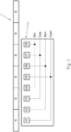
- the eight magnetic sensitive elements (Hall sensors, H1-H8) respectively included in the first sensing portion 41 or the second sensing portion 42 are arranged from left to right in sequence, and each of the magnetic sensitive elements H1-H8 is shifted on ⁇ /4 along a measuring axis respectively, as shown in FIG.
- ⁇ is a magnetic period of the magnet array 32, that is, a distance between the magnets 321 of a same magnetism, so that lengths of the first sensing portion 41 and the second sensing portion 42 are respectively equivalent to the two magnetic periods ⁇ , and the first magnetic sensitive element H1 and the fifth magnetic sensitive element H5, the second magnetic sensitive element H2 and the sixth magnetic sensitive element H6, the third magnetic sensitive element H3 and the seventh magnetic sensitive element H7, the fourth magnetic sensitive element H4 and the eighth magnetic sensitive element H8 are respectively connected in parallel to form four groups to optimize an average feedback error to improve accuracy and sensitivity of position feedback.
- the first sensing portion 41 is located on a left side of the stator 21, and the second sensing portion 42 is located on a right side of the stator 21; and in a Y-axis direction, in addition to the first sensing portion 41 and the second sensing portion 42 locating relative to a center of the magnets 321 of the magnet array 32 as shown in FIG. 5A , the first sensing portion 41 and the second sensing portion 42 can also be shifted along the Y-axis direction to be located on one side of the magnet array 32 (not shown in the figure).
- the third sensing portion 43 corresponds to one side of the magnet array 32.
- sine amplitude and cosine signal in sensing signals output by the second sensing portion 42 also have the same situation as that of the first sensing portion 41.
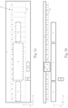
- the stator 21 is disposed in a space pattern of interposing between the first sensing portion 41 and the second sensing portion 42, a length L21 of the stator 21 is smaller than a separation distance L40 between the first sensing portion 41 and the second sensing portion 42, a length of the separation distance L40 is an integral multiple of the magnetic period ⁇ , and must have a length of at least four magnetic periods ⁇ to provide a sensing overlapping area 401 of the first sensing portion 41 and the second sensing portion 42 as shown in FIG. 6 , and when signals of the first sensing portion 41 and the second sensing portion 42 are combined, signals of cycles 402a, 402b with lower accuracy are excluded.
- a length of the magnet array 32 is equal to the length L1 of the measuring scale.
- the third sensing portion 43 is located in the overlapping area 401 to provide a unique and distinct juncture 433 as a signal juncture of the first sensing portion 41 and the second sensing portion 42.
- a disposing position of the third sensing portion 43 is limited.
- the signal unit 431 can be located in third and fourth overlapping periods in the overlapping area 401 of the first sensing portion 41 and the second sensing portion 42.
- the third sensing portion 43 is used to generate a unique and distinct zero point 434 in the overlapping area 401, and a position of the zero point 434 is defined by the signal unit 431 and the subcycle 414 of the first sensing portion 41, wherein the subcycle 414 of the first sensing portion 41 is equal to a threshold value ⁇ 10, for example, the threshold value ⁇ 10 shown in FIG. 6 is zero, and therefore, the length L431 of the signal unit 431 needs to satisfy formula 2: ⁇ ⁇ ⁇ 10 ⁇ ⁇ / 2 ⁇ ⁇ L 431 ⁇ 2 ⁇ ⁇ ⁇ ⁇ 10 ⁇ ⁇ / 2 ⁇
- an offset distance (Ls) (not shown in the figure) of the sensitive element 432 is less than one magnetic period ⁇ .
- the offset distance Ls of the sensitive element 432 is 1/4 magnetic period ⁇ , and the offset distance Lf of the signal unit 431 approaches zero.
- the invention is capable of calculating a measuring range 403 of the measurement module 40 according to an action pattern of the moving portion 30.
- a starting point 241 and an ending point 242 of the measuring range 403 of the measurement module 40 are defined according to the following formula 5, wherein Alowth is a low threshold value 249, for example Alowth is 25% of a rated amplitude, and Ahighth is a high threshold value 248, for example, Ahighth is 75% of a rated amplitude.
- the processing portion 44 calculates the amplitudes A1, 412 and the subcycles ⁇ 1, 414 of the first sensing portion 41, and amplitudes A2, 421 and subcycles ⁇ 2, 422 of the second sensing portion 42, which means that the amplitudes A1, 412 of the first sensing portion 41 are greater than the low threshold value 249, positions of the subcycles ⁇ 1, 414 of the first sensing portion 41 equal to 180°, the amplitudes A2, 421 of the second sensing portion 42 are lower than the high threshold value 248, and positions of the subcycles ⁇ 2, 422 of the second sensing portion 42 are 180°.
- Starting point : ⁇ A 1 > A lowth , ⁇ 1 180 °
- ending point : ⁇ A 2 ⁇ A highth , ⁇ 2 180 ° ,
- the starting point 241 and the ending point 242 of the measuring range 403 of the measurement module 40 are defined according to the following formula 6, which means that the amplitudes A1, 412 of the first sensing portion 41 are smaller than the high threshold value 248, positions of the subcycles ⁇ 1, 414 of the first sensing portion 41 equal to 180°, the amplitudes A2, 421 of the second sensing portion 42 are higher than the low threshold value 249, and positions of the subcycles ⁇ 2, 422 of the second sensing portion 42 are 180°.
- Starting point : ⁇ A 2 > A lowth , ⁇ 2 180 °
- ending point : ⁇ A 1 ⁇ A highth , ⁇ 1 180 ° ,
- the processing portion 44 feeds back calculated position information of the moving portion 30 to the driver 50, and then the driver 50 is used to control the stator 21 to perform current commutation.
- a separation distance L25 between the first sensing portion 41 and the stator 21 is adjusted so that each of the magnetic sensitive elements H1 ⁇ H8 of the first sensing portion 41 are in phase with a coil of the stator 21, thereby simplifying a power supply control mode of the stator 21.
- the measuring range 403 is further divided into a first measurement section 217 and a second measurement section 227 based on the juncture 433 as a reference, wherein when the carrier 31 is located on a left side of the juncture 433, the carrier 31 is located in the first measurement section 217, and then the subcycle 414 of the first sensing portion 41 is used to calculate a position of the moving portion 30, and the position is fed back; when the carrier 31 is located on a right side of the juncture 433, the carrier 31 is located in the second measurement section 227, and then the subcycle 422 of the second sensing portion 42 is used to calculate a position of the moving portion 30, and the position is fed back.
- a separation distance L11 between the first sensing portions 41 of each of the measurement modules 40 is equal to the length L1 of the magnet array
- the two magnet arrays 32 are taken as an example, the two magnet arrays 32 are coaxially fixed on the carrier 31 along a long axial direction, in order to ensure a correctness of the calculated starting point 241 and ending point 242, a minimum spacing 1010 between the two adjacent magnet arrays 32 is equal to a length L2 of the first sensing portion 41, and equivalent to the two magnetic periods ⁇ .
- at least one spacer 111, 112 is disposed between the two adjacent magnet arrays 32, and the minimum spacing 1010 is provided by a length of the at least one spacer 111, 112.
Landscapes
- Physics & Mathematics (AREA)
- General Physics & Mathematics (AREA)
- Transmission And Conversion Of Sensor Element Output (AREA)
Claims (6)
- Positionsmessmechanismus (10) umfassend:eine Basis (20);einen Bewegungsabschnitt (30), der in der Lage ist, sich relativ zu der Basis (20) zu bewegen;mindestens eine Magnetanordnung (32), die in dem Bewegungsabschnitt (30) angeordnet ist;einen ersten Sensorabschnitt (41) und einen zweiten Sensorabschnitt (42), die jeweils auf der Basis (20) in Intervallen angeordnet sind, um ein Magnetfeld der Magnetanordnung (32) zu erfassen;einen dritten Sensorabschnitt (43) mit einer Signaleinheit (431), die auf dem Bewegungsabschnitt (30) angeordnet ist, und einem Sensorelement (432), das auf der Basis (20) zum Erfassen der Signaleinheit (431) angeordnet ist; undeinen Verarbeitungsabschnitt (44), der Sensorsignale des ersten Sensorabschnitts (41) und des zweiten Sensorabschnitts (42) entsprechend empfängt, einen Unterzyklus (α1, α2, 414, 422) berechnet, der der Magnetanordnung (32) entspricht, und eine Operation in Verbindung mit Sensordaten des Sensorelements (432) durchführt, um einen Bewegungspfad des Bewegungsabschnitts (30) zu erhalten, und dann den Bewegungspfad zurück zu einem Treiber (50) führt, um ein Bewegungsmuster des Bewegungsabschnitts (30) einzustellen;wobei die Magnetanordnung (32) eine Vielzahl von Magneten (321) aufweist, ein minimaler Abstand zwischen den zwei Magneten (321) desselben Magnetismus eine magnetische Periode (τ) der Magnetanordnung (32) ist und eine Länge der Magnetanordnung (32) ein ganzzahliges Vielfaches der magnetischen Periode (τ) der Magnetanordnung (32) ist,wobei der Treiber (50) einen Strom eines Stators (21) steuert, der an der Basis (20) vorgesehen ist, und einen Feldbus (61) verwendet, um eine Verbindung mit einer Bewegungssteuerung (60) herzustellen,wobeider erste Sensorabschnitt (41) und der zweite Sensorabschnitt (42) jeweils acht magnetische Sensorelemente (H1, H2, H3, H4, H5, H6, H7, H8) umfassen, und jedes der magnetischen Sensorelemente (H1, H2, H3, H4, H5, H6, H7, H8) in der Reihenfolge von links nach rechts in einem Abstand von einem Viertel der magnetischen Periode (τ) der Magnetanordnung (32) angeordnet ist, das erste magnetische Sensorelement (H1) parallel mit dem fünften magnetischen Sensorelement (H5) verbunden ist, das zweite magnetische Sensorelement (H2) parallel zu dem sechsten magnetischen Sensorelement (H6) geschaltet ist, das dritte magnetische Sensorelement (H3) parallel zu dem siebten magnetischen Sensorelement (H7) geschaltet ist, und das vierte magnetische Sensorelement (H4) parallel zu dem achten magnetischen Sensorelement (H8) geschaltet ist;wobei der erste Sensorabschnitt (41) auf einer linken Seite des Stators (21) angeordnet ist und der zweite Sensorabschnitt (42) auf einer rechten Seite des Stators (21) angeordnet ist;ein Trennungsabstand (L40) zwischen dem ersten Sensorabschnitt (41) und dem zweiten Sensorabschnitt (42) ein ganzzahliges Vielfaches der magnetischen Periode (τ) der Magnetanordnung (32) ist; eine Länge der Magnetanordnung (32) größer ist als der Trennungsabstand (L40) zwischen dem ersten Sensorabschnitt (41) und dem zweiten Sensorabschnitt (42) und mindestens vier magnetische Perioden (τ) der Magnetanordnung (32) beträgt; undder dritte Sensorabschnitt (43) einen Verbindungspunkt (433) als Referenz bereitstellt, um Signale des ersten Sensorabschnitts (41) und des zweiten Sensorabschnitts (42) zu kombinieren.
- Positionsmessmechanismus (10) nach Anspruch 1, wobei die Anzahl der Magnetanordnungen (32) zwei beträgt und die Magnetanordnungen (32) nebeneinander auf dem Bewegungsabschnitt (30) angeordnet sind und der Abstand zwischen den beiden benachbarten Magnetanordnungen (32) mindestens zwei magnetische Perioden (τ) beträgt.
- Positionsmessmechanismus (10) nach Anspruch 1, ferner umfassend eine Vielzahl von Messmodulen (40), die jeweils den ersten Sensorabschnitt (41), den zweiten Sensorabschnitt (42) und den dritten Sensorabschnitt (43) umfassen, wobei ein Abstand zwischen den beiden benachbarten Messmodulen (40) gleich einer Länge der Magnetanordnung (32) ist.
- Positionsmessmechanismus (10) nach Anspruch 1, wobei der dritte Sensorabschnitt (43) Signale, die von dem ersten Sensorabschnitt (41) und dem zweiten Sensorabschnitt (42) in einem Messbereich (403) aufgenommen werden, jeweils mit dem Verbindungspunkt (433) kombiniert.
- Positionsmessmechanismus (10) nach Anspruch 4, wobei der Messbereich (403) in einen ersten Messabschnitt (217) des ersten Sensorabschnitts (41) und einen zweiten Messabschnitt (227) des zweiten Sensorabschnitts (42) mit dem Verbindungspunkt (433) unterteilt ist, wobei der erste Messabschnitt (217) und der zweite Messabschnitt (227) jeweils entlang einer Bewegungsrichtung des Bewegungsabschnitts (30) konfiguriert sind und einander benachbart sind.
- Positionsmessmechanismus (10) nach Anspruch 5, wobei:wenn sich der Bewegungsabschnitt (30) von rechts nach links bewegt und verschiebt, ein Startpunkt (241) des Messbereichs (403) definiert ist als: eine Amplitude (A1, 412) des von dem ersten Sensorabschnitt (41) aufgenommenen Signals ist kleiner als ein vorbestimmter hoher Schwellenwert (248), und eine Position des Unterzyklus (α1, 414) des von dem ersten Sensorabschnitt (41) aufgenommenen Signals ist gleich 180°; ein Endpunkt (242) des Messbereichs (403) definiert ist als: eine Amplitude (A2, 421) des von dem zweiten Sensorabschnitt (42) aufgenommenen Signals höher ist als ein vorbestimmter unterer Schwellenwert (249), und eine Position des Unterzyklus (α2, 422) des von dem zweiten Sensorabschnitt (42) aufgenommenen Signals gleich 180° ist; undwenn sich der Bewegungsabschnitt (30) bewegt und von links nach rechts verschiebt, ein Startpunkt (241) des Messbereichs (403) definiert ist als: die Amplitude (A1, 412) des vom ersten Sensorabschnitt (41) aufgenommenen Signals ist größer als der untere Schwellenwert (249), und die Position des Unterzyklus (α1, 414) des vom ersten Sensorabschnitt (41) aufgenommenen Signals ist gleich 180°, ein Endpunkt (242) des Messbereichs (403) ist definiert als: die Amplitude (A2, 421) des von dem zweiten Sensorabschnitt (42) aufgenommenen Signals ist kleiner als der untere Schwellenwert (249) und die Position des Unterzyklus (α2, 422) des von dem zweiten Sensorabschnitt (42) aufgenommenen Signals ist gleich 180°.
Priority Applications (1)
| Application Number | Priority Date | Filing Date | Title |
|---|---|---|---|
| EP21151708.1A EP4030146B1 (de) | 2021-01-14 | 2021-01-14 | Positionsmessmechanismus und messverfahren für ein linearbewegungssystem |
Applications Claiming Priority (1)
| Application Number | Priority Date | Filing Date | Title |
|---|---|---|---|
| EP21151708.1A EP4030146B1 (de) | 2021-01-14 | 2021-01-14 | Positionsmessmechanismus und messverfahren für ein linearbewegungssystem |
Publications (2)
| Publication Number | Publication Date |
|---|---|
| EP4030146A1 EP4030146A1 (de) | 2022-07-20 |
| EP4030146B1 true EP4030146B1 (de) | 2024-07-17 |
Family
ID=74184539
Family Applications (1)
| Application Number | Title | Priority Date | Filing Date |
|---|---|---|---|
| EP21151708.1A Active EP4030146B1 (de) | 2021-01-14 | 2021-01-14 | Positionsmessmechanismus und messverfahren für ein linearbewegungssystem |
Country Status (1)
| Country | Link |
|---|---|
| EP (1) | EP4030146B1 (de) |
Family Cites Families (9)
| Publication number | Priority date | Publication date | Assignee | Title |
|---|---|---|---|---|
| US5994798A (en) | 1998-02-26 | 1999-11-30 | Anorad Corporation | Closed-path linear motor |
| EP2182627B1 (de) | 2008-10-31 | 2012-02-01 | Robert Bosch GmbH | Verfahren und Vorrichtung zur Steuerung eines linearen Bewegungssystems |
| JP5567823B2 (ja) | 2009-11-09 | 2014-08-06 | ヤマハ発動機株式会社 | リニアスケール、リニアモータ、及びリニアモータの制御装置 |
| DE102010028333A1 (de) | 2010-04-28 | 2011-11-03 | Robert Bosch Gmbh | Inkrementelles Multipositions-Erfassungssystem für ein umlaufendes elektromagnetisches Transfersystem |
| EP2634913A4 (de) | 2010-10-26 | 2017-02-22 | Murata Machinery, Ltd. | Verteiltes linearmotorsystem |
| EP3015933B1 (de) | 2014-10-27 | 2019-10-02 | Robert Bosch Gmbh | Transportsystem |
| JP6626982B2 (ja) | 2016-09-21 | 2019-12-25 | ヤマハ発動機株式会社 | リニアコンベア装置 |
| US10906748B2 (en) * | 2017-08-09 | 2021-02-02 | Rockwell Automation Technologies, Inc. | Method and apparatus for identifying a mover on a closed track |
| US10914620B2 (en) * | 2018-11-27 | 2021-02-09 | Rockwell Automation Technologies, Inc. | System and method for automatic runtime position sensor gain calibration in a linear motion system |
-
2021
- 2021-01-14 EP EP21151708.1A patent/EP4030146B1/de active Active
Also Published As
| Publication number | Publication date |
|---|---|
| EP4030146A1 (de) | 2022-07-20 |
Similar Documents
| Publication | Publication Date | Title |
|---|---|---|
| US8497643B2 (en) | Linear scale, linear motor, and linear motor controller | |
| US7723942B1 (en) | Integrated motor and resolver including absolute position capability | |
| US5412317A (en) | Position detector utilizing absolute and incremental position sensors in combination | |
| US7538460B2 (en) | Integrated resolver for high pole count motors | |
| US8497764B2 (en) | Position transmitter system | |
| US7746064B2 (en) | Speed measurement for an electrical permanent-magnet synchronous machine | |
| CN102474217A (zh) | 分布式布置的直线电机及分布式布置的直线电机的控制方法 | |
| EP3982089B1 (de) | Magnetisches sensorsystem zur motorsteuerung | |
| US20180216967A1 (en) | Hybrid Encoder System for Position Determination | |
| US20220333954A1 (en) | Multi-sensor position measurement system | |
| US7999535B2 (en) | Measuring device for determining a position between a primary part and a secondary part by magnetic flux measurements | |
| EP4030146B1 (de) | Positionsmessmechanismus und messverfahren für ein linearbewegungssystem | |
| JP5529637B2 (ja) | リニアモータの位置検出システム | |
| US11774521B2 (en) | Position measuring mechanism and measuring method of linear motion system | |
| WO2008072525A1 (ja) | シャフト型リニアモータの位置決め装置 | |
| CN217604900U (zh) | 一种电感式线性编码器及具有其的直线电机 | |
| KR102533280B1 (ko) | 선형 운동 시스템의 위치 측정 기구 및 이의 측정 방법 | |
| JP7148653B2 (ja) | リニア運動システムの位置測定機構及びその測定方法 | |
| US5072179A (en) | High resolution one and two dimensional position indicating apparatus with plural windings having a common connection and separately energized by signals of different phase | |
| TWI774180B (zh) | 線性運動系統之位置量測機構及其量測方法 | |
| Lequesne et al. | High-accuracy magnetic position encoder concept | |
| CN114739272A (zh) | 线性运动系统的位置量测机构及其量测方法 | |
| Poltschak et al. | Embedded Absolute Position Detection for Permanent Magnet Linear Motors with Passive Track | |
| KR20230130559A (ko) | 측위장치, 구동장치, 측위방법, 측위프로그램을 기록한 컴퓨터로 독취 가능한 기록매체 | |
| KR102692275B1 (ko) | 멀티 센서 위치측정 시스템 |
Legal Events
| Date | Code | Title | Description |
|---|---|---|---|
| PUAI | Public reference made under article 153(3) epc to a published international application that has entered the european phase |
Free format text: ORIGINAL CODE: 0009012 |
|
| STAA | Information on the status of an ep patent application or granted ep patent |
Free format text: STATUS: THE APPLICATION HAS BEEN PUBLISHED |
|
| AK | Designated contracting states |
Kind code of ref document: A1 Designated state(s): AL AT BE BG CH CY CZ DE DK EE ES FI FR GB GR HR HU IE IS IT LI LT LU LV MC MK MT NL NO PL PT RO RS SE SI SK SM TR |
|
| STAA | Information on the status of an ep patent application or granted ep patent |
Free format text: STATUS: REQUEST FOR EXAMINATION WAS MADE |
|
| 17P | Request for examination filed |
Effective date: 20230118 |
|
| RBV | Designated contracting states (corrected) |
Designated state(s): AL AT BE BG CH CY CZ DE DK EE ES FI FR GB GR HR HU IE IS IT LI LT LU LV MC MK MT NL NO PL PT RO RS SE SI SK SM TR |
|
| GRAP | Despatch of communication of intention to grant a patent |
Free format text: ORIGINAL CODE: EPIDOSNIGR1 |
|
| STAA | Information on the status of an ep patent application or granted ep patent |
Free format text: STATUS: GRANT OF PATENT IS INTENDED |
|
| RIC1 | Information provided on ipc code assigned before grant |
Ipc: G01D 5/245 20060101ALI20240130BHEP Ipc: G01D 5/14 20060101AFI20240130BHEP |
|
| INTG | Intention to grant announced |
Effective date: 20240216 |
|
| GRAS | Grant fee paid |
Free format text: ORIGINAL CODE: EPIDOSNIGR3 |
|
| GRAA | (expected) grant |
Free format text: ORIGINAL CODE: 0009210 |
|
| STAA | Information on the status of an ep patent application or granted ep patent |
Free format text: STATUS: THE PATENT HAS BEEN GRANTED |
|
| AK | Designated contracting states |
Kind code of ref document: B1 Designated state(s): AL AT BE BG CH CY CZ DE DK EE ES FI FR GB GR HR HU IE IS IT LI LT LU LV MC MK MT NL NO PL PT RO RS SE SI SK SM TR |
|
| REG | Reference to a national code |
Ref country code: CH Ref legal event code: EP |
|
| REG | Reference to a national code |
Ref country code: DE Ref legal event code: R096 Ref document number: 602021015653 Country of ref document: DE |
|
| REG | Reference to a national code |
Ref country code: IE Ref legal event code: FG4D |
|
| REG | Reference to a national code |
Ref country code: SE Ref legal event code: TRGR |
|
| REG | Reference to a national code |
Ref country code: LT Ref legal event code: MG9D |
|
| REG | Reference to a national code |
Ref country code: NL Ref legal event code: MP Effective date: 20240717 |
|
| PG25 | Lapsed in a contracting state [announced via postgrant information from national office to epo] |
Ref country code: PT Free format text: LAPSE BECAUSE OF FAILURE TO SUBMIT A TRANSLATION OF THE DESCRIPTION OR TO PAY THE FEE WITHIN THE PRESCRIBED TIME-LIMIT Effective date: 20241118 |
|
| REG | Reference to a national code |
Ref country code: AT Ref legal event code: MK05 Ref document number: 1704532 Country of ref document: AT Kind code of ref document: T Effective date: 20240717 |
|
| PG25 | Lapsed in a contracting state [announced via postgrant information from national office to epo] |
Ref country code: NL Free format text: LAPSE BECAUSE OF FAILURE TO SUBMIT A TRANSLATION OF THE DESCRIPTION OR TO PAY THE FEE WITHIN THE PRESCRIBED TIME-LIMIT Effective date: 20240717 |
|
| PG25 | Lapsed in a contracting state [announced via postgrant information from national office to epo] |
Ref country code: PT Free format text: LAPSE BECAUSE OF FAILURE TO SUBMIT A TRANSLATION OF THE DESCRIPTION OR TO PAY THE FEE WITHIN THE PRESCRIBED TIME-LIMIT Effective date: 20241118 Ref country code: NL Free format text: LAPSE BECAUSE OF FAILURE TO SUBMIT A TRANSLATION OF THE DESCRIPTION OR TO PAY THE FEE WITHIN THE PRESCRIBED TIME-LIMIT Effective date: 20240717 |
|
| PG25 | Lapsed in a contracting state [announced via postgrant information from national office to epo] |
Ref country code: NO Free format text: LAPSE BECAUSE OF FAILURE TO SUBMIT A TRANSLATION OF THE DESCRIPTION OR TO PAY THE FEE WITHIN THE PRESCRIBED TIME-LIMIT Effective date: 20241017 |
|
| PG25 | Lapsed in a contracting state [announced via postgrant information from national office to epo] |
Ref country code: FI Free format text: LAPSE BECAUSE OF FAILURE TO SUBMIT A TRANSLATION OF THE DESCRIPTION OR TO PAY THE FEE WITHIN THE PRESCRIBED TIME-LIMIT Effective date: 20240717 Ref country code: PL Free format text: LAPSE BECAUSE OF FAILURE TO SUBMIT A TRANSLATION OF THE DESCRIPTION OR TO PAY THE FEE WITHIN THE PRESCRIBED TIME-LIMIT Effective date: 20240717 Ref country code: GR Free format text: LAPSE BECAUSE OF FAILURE TO SUBMIT A TRANSLATION OF THE DESCRIPTION OR TO PAY THE FEE WITHIN THE PRESCRIBED TIME-LIMIT Effective date: 20241018 |
|
| PG25 | Lapsed in a contracting state [announced via postgrant information from national office to epo] |
Ref country code: BG Free format text: LAPSE BECAUSE OF FAILURE TO SUBMIT A TRANSLATION OF THE DESCRIPTION OR TO PAY THE FEE WITHIN THE PRESCRIBED TIME-LIMIT Effective date: 20240717 |
|
| PG25 | Lapsed in a contracting state [announced via postgrant information from national office to epo] |
Ref country code: LV Free format text: LAPSE BECAUSE OF FAILURE TO SUBMIT A TRANSLATION OF THE DESCRIPTION OR TO PAY THE FEE WITHIN THE PRESCRIBED TIME-LIMIT Effective date: 20240717 |
|
| PG25 | Lapsed in a contracting state [announced via postgrant information from national office to epo] |
Ref country code: IS Free format text: LAPSE BECAUSE OF FAILURE TO SUBMIT A TRANSLATION OF THE DESCRIPTION OR TO PAY THE FEE WITHIN THE PRESCRIBED TIME-LIMIT Effective date: 20241117 Ref country code: AT Free format text: LAPSE BECAUSE OF FAILURE TO SUBMIT A TRANSLATION OF THE DESCRIPTION OR TO PAY THE FEE WITHIN THE PRESCRIBED TIME-LIMIT Effective date: 20240717 |
|
| PG25 | Lapsed in a contracting state [announced via postgrant information from national office to epo] |
Ref country code: HR Free format text: LAPSE BECAUSE OF FAILURE TO SUBMIT A TRANSLATION OF THE DESCRIPTION OR TO PAY THE FEE WITHIN THE PRESCRIBED TIME-LIMIT Effective date: 20240717 |
|
| PG25 | Lapsed in a contracting state [announced via postgrant information from national office to epo] |
Ref country code: ES Free format text: LAPSE BECAUSE OF FAILURE TO SUBMIT A TRANSLATION OF THE DESCRIPTION OR TO PAY THE FEE WITHIN THE PRESCRIBED TIME-LIMIT Effective date: 20240717 Ref country code: RS Free format text: LAPSE BECAUSE OF FAILURE TO SUBMIT A TRANSLATION OF THE DESCRIPTION OR TO PAY THE FEE WITHIN THE PRESCRIBED TIME-LIMIT Effective date: 20241017 |
|
| PG25 | Lapsed in a contracting state [announced via postgrant information from national office to epo] |
Ref country code: RS Free format text: LAPSE BECAUSE OF FAILURE TO SUBMIT A TRANSLATION OF THE DESCRIPTION OR TO PAY THE FEE WITHIN THE PRESCRIBED TIME-LIMIT Effective date: 20241017 Ref country code: PL Free format text: LAPSE BECAUSE OF FAILURE TO SUBMIT A TRANSLATION OF THE DESCRIPTION OR TO PAY THE FEE WITHIN THE PRESCRIBED TIME-LIMIT Effective date: 20240717 Ref country code: NO Free format text: LAPSE BECAUSE OF FAILURE TO SUBMIT A TRANSLATION OF THE DESCRIPTION OR TO PAY THE FEE WITHIN THE PRESCRIBED TIME-LIMIT Effective date: 20241017 Ref country code: LV Free format text: LAPSE BECAUSE OF FAILURE TO SUBMIT A TRANSLATION OF THE DESCRIPTION OR TO PAY THE FEE WITHIN THE PRESCRIBED TIME-LIMIT Effective date: 20240717 Ref country code: IS Free format text: LAPSE BECAUSE OF FAILURE TO SUBMIT A TRANSLATION OF THE DESCRIPTION OR TO PAY THE FEE WITHIN THE PRESCRIBED TIME-LIMIT Effective date: 20241117 Ref country code: HR Free format text: LAPSE BECAUSE OF FAILURE TO SUBMIT A TRANSLATION OF THE DESCRIPTION OR TO PAY THE FEE WITHIN THE PRESCRIBED TIME-LIMIT Effective date: 20240717 Ref country code: GR Free format text: LAPSE BECAUSE OF FAILURE TO SUBMIT A TRANSLATION OF THE DESCRIPTION OR TO PAY THE FEE WITHIN THE PRESCRIBED TIME-LIMIT Effective date: 20241018 Ref country code: FI Free format text: LAPSE BECAUSE OF FAILURE TO SUBMIT A TRANSLATION OF THE DESCRIPTION OR TO PAY THE FEE WITHIN THE PRESCRIBED TIME-LIMIT Effective date: 20240717 Ref country code: ES Free format text: LAPSE BECAUSE OF FAILURE TO SUBMIT A TRANSLATION OF THE DESCRIPTION OR TO PAY THE FEE WITHIN THE PRESCRIBED TIME-LIMIT Effective date: 20240717 Ref country code: BG Free format text: LAPSE BECAUSE OF FAILURE TO SUBMIT A TRANSLATION OF THE DESCRIPTION OR TO PAY THE FEE WITHIN THE PRESCRIBED TIME-LIMIT Effective date: 20240717 Ref country code: AT Free format text: LAPSE BECAUSE OF FAILURE TO SUBMIT A TRANSLATION OF THE DESCRIPTION OR TO PAY THE FEE WITHIN THE PRESCRIBED TIME-LIMIT Effective date: 20240717 |
|
| PG25 | Lapsed in a contracting state [announced via postgrant information from national office to epo] |
Ref country code: DK Free format text: LAPSE BECAUSE OF FAILURE TO SUBMIT A TRANSLATION OF THE DESCRIPTION OR TO PAY THE FEE WITHIN THE PRESCRIBED TIME-LIMIT Effective date: 20240717 Ref country code: RO Free format text: LAPSE BECAUSE OF FAILURE TO SUBMIT A TRANSLATION OF THE DESCRIPTION OR TO PAY THE FEE WITHIN THE PRESCRIBED TIME-LIMIT Effective date: 20240717 Ref country code: SM Free format text: LAPSE BECAUSE OF FAILURE TO SUBMIT A TRANSLATION OF THE DESCRIPTION OR TO PAY THE FEE WITHIN THE PRESCRIBED TIME-LIMIT Effective date: 20240717 |
|
| REG | Reference to a national code |
Ref country code: DE Ref legal event code: R097 Ref document number: 602021015653 Country of ref document: DE |
|
| PG25 | Lapsed in a contracting state [announced via postgrant information from national office to epo] |
Ref country code: EE Free format text: LAPSE BECAUSE OF FAILURE TO SUBMIT A TRANSLATION OF THE DESCRIPTION OR TO PAY THE FEE WITHIN THE PRESCRIBED TIME-LIMIT Effective date: 20240717 |
|
| PG25 | Lapsed in a contracting state [announced via postgrant information from national office to epo] |
Ref country code: CZ Free format text: LAPSE BECAUSE OF FAILURE TO SUBMIT A TRANSLATION OF THE DESCRIPTION OR TO PAY THE FEE WITHIN THE PRESCRIBED TIME-LIMIT Effective date: 20240717 |
|
| PG25 | Lapsed in a contracting state [announced via postgrant information from national office to epo] |
Ref country code: SK Free format text: LAPSE BECAUSE OF FAILURE TO SUBMIT A TRANSLATION OF THE DESCRIPTION OR TO PAY THE FEE WITHIN THE PRESCRIBED TIME-LIMIT Effective date: 20240717 |
|
| PLBE | No opposition filed within time limit |
Free format text: ORIGINAL CODE: 0009261 |
|
| STAA | Information on the status of an ep patent application or granted ep patent |
Free format text: STATUS: NO OPPOSITION FILED WITHIN TIME LIMIT |
|
| 26N | No opposition filed |
Effective date: 20250422 |
|
| REG | Reference to a national code |
Ref country code: CH Ref legal event code: PL |
|
| PG25 | Lapsed in a contracting state [announced via postgrant information from national office to epo] |
Ref country code: LU Free format text: LAPSE BECAUSE OF NON-PAYMENT OF DUE FEES Effective date: 20250114 Ref country code: MC Free format text: LAPSE BECAUSE OF FAILURE TO SUBMIT A TRANSLATION OF THE DESCRIPTION OR TO PAY THE FEE WITHIN THE PRESCRIBED TIME-LIMIT Effective date: 20240717 |
|
| GBPC | Gb: european patent ceased through non-payment of renewal fee |
Effective date: 20250114 |
|
| PG25 | Lapsed in a contracting state [announced via postgrant information from national office to epo] |
Ref country code: BE Free format text: LAPSE BECAUSE OF NON-PAYMENT OF DUE FEES Effective date: 20250131 Ref country code: GB Free format text: LAPSE BECAUSE OF NON-PAYMENT OF DUE FEES Effective date: 20250114 |
|
| PG25 | Lapsed in a contracting state [announced via postgrant information from national office to epo] |
Ref country code: FR Free format text: LAPSE BECAUSE OF NON-PAYMENT OF DUE FEES Effective date: 20250131 |
|
| PG25 | Lapsed in a contracting state [announced via postgrant information from national office to epo] |
Ref country code: CH Free format text: LAPSE BECAUSE OF NON-PAYMENT OF DUE FEES Effective date: 20250131 |
|
| REG | Reference to a national code |
Ref country code: BE Ref legal event code: MM Effective date: 20250131 |
|
| PG25 | Lapsed in a contracting state [announced via postgrant information from national office to epo] |
Ref country code: IT Free format text: LAPSE BECAUSE OF NON-PAYMENT OF DUE FEES Effective date: 20250114 |
|
| PG25 | Lapsed in a contracting state [announced via postgrant information from national office to epo] |
Ref country code: IE Free format text: LAPSE BECAUSE OF NON-PAYMENT OF DUE FEES Effective date: 20250114 |
|
| PGFP | Annual fee paid to national office [announced via postgrant information from national office to epo] |
Ref country code: SE Payment date: 20260127 Year of fee payment: 6 |
|
| PGFP | Annual fee paid to national office [announced via postgrant information from national office to epo] |
Ref country code: DE Payment date: 20260128 Year of fee payment: 6 |
|
| PG25 | Lapsed in a contracting state [announced via postgrant information from national office to epo] |
Ref country code: IT Free format text: LAPSE BECAUSE OF NON-PAYMENT OF DUE FEES Effective date: 20250114 |
|
| PGFP | Annual fee paid to national office [announced via postgrant information from national office to epo] |
Ref country code: IT Payment date: 20260121 Year of fee payment: 6 |
|
| PGRI | Patent reinstated in contracting state [announced from national office to epo] |
Ref country code: IT Effective date: 20250603 |