EP4031893B1 - Génération d'enregistrements irm du foie - Google Patents
Génération d'enregistrements irm du foie Download PDFInfo
- Publication number
- EP4031893B1 EP4031893B1 EP20771810.7A EP20771810A EP4031893B1 EP 4031893 B1 EP4031893 B1 EP 4031893B1 EP 20771810 A EP20771810 A EP 20771810A EP 4031893 B1 EP4031893 B1 EP 4031893B1
- Authority
- EP
- European Patent Office
- Prior art keywords
- mri image
- liver
- mri
- contrast
- blood vessels
- Prior art date
- Legal status (The legal status is an assumption and is not a legal conclusion. Google has not performed a legal analysis and makes no representation as to the accuracy of the status listed.)
- Active
Links
Images



Classifications
-
- G—PHYSICS
- G01—MEASURING; TESTING
- G01R—MEASURING ELECTRIC VARIABLES; MEASURING MAGNETIC VARIABLES
- G01R33/00—Arrangements or instruments for measuring magnetic variables
- G01R33/20—Arrangements or instruments for measuring magnetic variables involving magnetic resonance
- G01R33/44—Arrangements or instruments for measuring magnetic variables involving magnetic resonance using nuclear magnetic resonance [NMR]
- G01R33/48—NMR imaging systems
-
- G—PHYSICS
- G01—MEASURING; TESTING
- G01R—MEASURING ELECTRIC VARIABLES; MEASURING MAGNETIC VARIABLES
- G01R33/00—Arrangements or instruments for measuring magnetic variables
- G01R33/20—Arrangements or instruments for measuring magnetic variables involving magnetic resonance
- G01R33/44—Arrangements or instruments for measuring magnetic variables involving magnetic resonance using nuclear magnetic resonance [NMR]
- G01R33/48—NMR imaging systems
- G01R33/54—Signal processing systems, e.g. using pulse sequences ; Generation or control of pulse sequences; Operator console
- G01R33/56—Image enhancement or correction, e.g. subtraction or averaging techniques, e.g. improvement of signal-to-noise ratio and resolution
- G01R33/5608—Data processing and visualization specially adapted for MR, e.g. for feature analysis and pattern recognition on the basis of measured MR data, segmentation of measured MR data, edge contour detection on the basis of measured MR data, for enhancing measured MR data in terms of signal-to-noise ratio by means of noise filtering or apodization, for enhancing measured MR data in terms of resolution by means for deblurring, windowing, zero filling, or generation of gray-scaled images, colour-coded images or images displaying vectors instead of pixels
-
- A—HUMAN NECESSITIES
- A61—MEDICAL OR VETERINARY SCIENCE; HYGIENE
- A61B—DIAGNOSIS; SURGERY; IDENTIFICATION
- A61B5/00—Measuring for diagnostic purposes; Identification of persons
- A61B5/42—Detecting, measuring or recording for evaluating the gastrointestinal, the endocrine or the exocrine systems
- A61B5/4222—Evaluating particular parts, e.g. particular organs
- A61B5/4244—Evaluating particular parts, e.g. particular organs liver
-
- A—HUMAN NECESSITIES
- A61—MEDICAL OR VETERINARY SCIENCE; HYGIENE
- A61B—DIAGNOSIS; SURGERY; IDENTIFICATION
- A61B5/00—Measuring for diagnostic purposes; Identification of persons
- A61B5/05—Detecting, measuring or recording for diagnosis by means of electric currents or magnetic fields; Measuring using microwaves or radio waves
- A61B5/055—Detecting, measuring or recording for diagnosis by means of electric currents or magnetic fields; Measuring using microwaves or radio waves involving electronic [EMR] or nuclear [NMR] magnetic resonance, e.g. magnetic resonance imaging
-
- G—PHYSICS
- G01—MEASURING; TESTING
- G01R—MEASURING ELECTRIC VARIABLES; MEASURING MAGNETIC VARIABLES
- G01R33/00—Arrangements or instruments for measuring magnetic variables
- G01R33/20—Arrangements or instruments for measuring magnetic variables involving magnetic resonance
- G01R33/44—Arrangements or instruments for measuring magnetic variables involving magnetic resonance using nuclear magnetic resonance [NMR]
- G01R33/48—NMR imaging systems
- G01R33/54—Signal processing systems, e.g. using pulse sequences ; Generation or control of pulse sequences; Operator console
- G01R33/56—Image enhancement or correction, e.g. subtraction or averaging techniques, e.g. improvement of signal-to-noise ratio and resolution
-
- G—PHYSICS
- G01—MEASURING; TESTING
- G01R—MEASURING ELECTRIC VARIABLES; MEASURING MAGNETIC VARIABLES
- G01R33/00—Arrangements or instruments for measuring magnetic variables
- G01R33/20—Arrangements or instruments for measuring magnetic variables involving magnetic resonance
- G01R33/44—Arrangements or instruments for measuring magnetic variables involving magnetic resonance using nuclear magnetic resonance [NMR]
- G01R33/48—NMR imaging systems
- G01R33/54—Signal processing systems, e.g. using pulse sequences ; Generation or control of pulse sequences; Operator console
- G01R33/56—Image enhancement or correction, e.g. subtraction or averaging techniques, e.g. improvement of signal-to-noise ratio and resolution
- G01R33/5601—Image enhancement or correction, e.g. subtraction or averaging techniques, e.g. improvement of signal-to-noise ratio and resolution involving use of a contrast agent for contrast manipulation, e.g. a paramagnetic, super-paramagnetic, ferromagnetic or hyperpolarised contrast agent
-
- G—PHYSICS
- G01—MEASURING; TESTING
- G01R—MEASURING ELECTRIC VARIABLES; MEASURING MAGNETIC VARIABLES
- G01R33/00—Arrangements or instruments for measuring magnetic variables
- G01R33/20—Arrangements or instruments for measuring magnetic variables involving magnetic resonance
- G01R33/44—Arrangements or instruments for measuring magnetic variables involving magnetic resonance using nuclear magnetic resonance [NMR]
- G01R33/48—NMR imaging systems
- G01R33/54—Signal processing systems, e.g. using pulse sequences ; Generation or control of pulse sequences; Operator console
- G01R33/56—Image enhancement or correction, e.g. subtraction or averaging techniques, e.g. improvement of signal-to-noise ratio and resolution
- G01R33/5602—Image enhancement or correction, e.g. subtraction or averaging techniques, e.g. improvement of signal-to-noise ratio and resolution by filtering or weighting based on different relaxation times within the sample, e.g. T1 weighting using an inversion pulse
-
- G—PHYSICS
- G06—COMPUTING OR CALCULATING; COUNTING
- G06T—IMAGE DATA PROCESSING OR GENERATION, IN GENERAL
- G06T7/00—Image analysis
- G06T7/0002—Inspection of images, e.g. flaw detection
- G06T7/0012—Biomedical image inspection
-
- G—PHYSICS
- G06—COMPUTING OR CALCULATING; COUNTING
- G06T—IMAGE DATA PROCESSING OR GENERATION, IN GENERAL
- G06T2207/00—Indexing scheme for image analysis or image enhancement
- G06T2207/10—Image acquisition modality
- G06T2207/10072—Tomographic images
- G06T2207/10088—Magnetic resonance imaging [MRI]
Definitions
- the present invention relates to the generation of artificial MRI images of the liver.
- the present invention relates to a method, a system and a computer program product for generating MRI images of the liver.
- Magnetic resonance imaging abbreviated to MRI or MR, is an imaging technique used primarily in medical diagnostics to depict the structure and function of tissues and organs in the human or animal body.
- MR imaging the magnetic moments of protons in an object under investigation are aligned in a basic magnetic field so that a macroscopic magnetization is established along a longitudinal direction. This is then deflected from the rest position by irradiating high frequency (HF) pulses (excitation). The return of the excited states to the rest position (relaxation) or the magnetization dynamics is then detected as relaxation signals using one or more HF receiving coils.
- HF high frequency
- the recorded relaxation signals or the detected and spatially resolved MR data are initially available as raw data in a spatial frequency space and can be transformed into the spatial space (image space) by subsequent Fourier transformation.
- the tissue contrasts are generated by the different relaxation times (T1 and T2) and the proton density.
- the T1 relaxation describes the transition of the longitudinal magnetization to its equilibrium state, where T1 is the time required to reach 63.21% of the equilibrium magnetization before resonance excitation. It is also called longitudinal relaxation time or spin-lattice relaxation time.
- the T2 relaxation describes in an analogous manner the transition of the transverse magnetization to its equilibrium state.
- MR contrast agents work by changing the relaxation times of the structures that absorb the contrast agent.
- Two groups of substances can be distinguished: paramagnetic and superparamagnetic substances. Both groups of substances have unpaired electrons that induce a magnetic field around the individual atoms or molecules.
- Superparamagnetic contrast agents lead to a predominant T2 shortening, while paramagnetic contrast agents lead essentially to a T1 shortening.
- a shortening of the T1 time leads to an increase in signal intensity, a shortening of the T2 time leads to a decrease in signal intensity.
- contrast agents are indirect, since the contrast agent itself does not emit a signal but only influences the signal intensity in its surroundings.
- paramagnetic contrast agents result in brighter (higher signal) representation of the areas containing contrast agents compared to the areas not containing contrast agents.
- Both a higher signal level and a lower signal level display lead to an increase in contrast.
- An example of a superparamagnetic contrast agent is iron oxide nanoparticles (SPIO) .
- paramagnetic contrast agents examples include gadolinium chelates such as gadopentetate dimeglumine (trade name: Magnevist ® , among others), gadobenate dimeglumine (trade name: Multihance ® ), gadoteric acid (Dotarem ® , Dotagita ® , Cyclolux ® ), gadodiamide (Omniscan ® ), gadoteridol (ProHance ® ) and gadobutrol (Gadovist ® ).
- gadolinium chelates such as gadopentetate dimeglumine (trade name: Magnevist ® , among others), gadobenate dimeglumine (trade name: Multihance ® ), gadoteric acid (Dotarem ® , Dotagita ® , Cyclolux ® ), gadodiamide (Omniscan ® ), gadoteridol (ProHance ®
- extracellular, intracellular and intravascular contrast agents can be distinguished.
- Contrast agents based on gadoxetic acid are characterized by the fact that they are specifically absorbed by liver cells, the hepatocytes, accumulate in the functional tissue (parenchyma) and increase the contrast in healthy liver tissue.
- the cells of cysts, metastases and most hepatocellular carcinomas no longer function like normal liver cells, do not absorb the contrast agent or only absorb it to a very small extent, are not enhanced and are therefore recognizable and localizable.
- contrast agents based on gadoxetic acid are US 6,039,931A They are commercially available, for example, under the brand names Primovist ® or Eovist ® .
- the contrast-enhancing effect of Primovist ® /Eovist ® is mediated by the stable gadolinium complex Gd-EOB-DTPA (gadolinium-ethoxybenzyl-diethylenetriamine-pentaacetic acid).
- Gd-EOB-DTPA gadolinium-ethoxybenzyl-diethylenetriamine-pentaacetic acid
- DTPA forms a complex with the paramagnetic gadolinium ion that has an extremely high thermodynamic stability.
- the ethoxybenzyl residue (EOB) mediates the hepatobiliary uptake of the contrast agent.
- the blood supply to healthy liver tissue is primarily via the portal vein ( vena portae ), while the hepatic artery ( arteria hepatica ) supplies most primary tumors.
- a time delay can be observed between the signal increase of the healthy liver parenchyma and the tumor.
- Ding Hwan Kim et al. disclose a method for diagnosing early-stage hepatocellular carcinoma based on an MRI image generated by subtracting a native MRI image from an MRI image in the arterial phase ( Ding Hwan Kim et al.: Arterial subtraction images of gadocetate-enhanded MRI improve diagnosis of earl-stage hepatocellular carcinoma, J. Hepatol., 2019, 71, 534-542 ).
- Primovist ® leads to a significant signal enhancement in the healthy liver parenchyma 10-20 minutes after injection (in the hepatobiliary phase), while lesions that contain no or few hepatocytes, e.g. metastases or moderately to poorly differentiated hepatocellular carcinomas (HCCs), appear as darker areas.
- HCCs poorly differentiated hepatocellular carcinomas
- the blood vessels also appear as dark areas, so that differentiation between liver lesions and blood vessels on the basis of contrast alone is not possible in the MRI images generated during the hepatobiliary phase. Differentiation between liver lesions and blood vessels can only be made in the context of images in the dynamic phase, in which the blood vessels are highlighted. The radiologist must therefore remember the blood vessels when looking at MRI images generated during the dynamic phase in order to be able to distinguish them from liver lesions in MRI images generated during the hepatobiliary phase.
- Both P. Bannas et al. and G. Knobloch et al. propose to apply two different contrast agents at different times to differentiate liver lesions from blood vessels in the hepatobiliary phase ( P. Bannas et al.: Combined Gadoxetic Acid and Gadofosveset Enhanced Liver MRI: A Feasibility Study and Parameter Optimization, Magnetic Resonance in Medicine, 2016, 75: 318-326 ; G. Knobloch et al.: Combined Gadoxetic Acid and Gadobenate Dimeglumine Enhanced Liver MRI for Liver Metastasis Detection: A Parameter Optimization Study, International Society for Magnetic Resonance in Medicine, No. 75, 2018 ).
- the administration of two contrast agents instead of one is an additional effort that may involve an additional risk for the patient. In addition, it can be difficult to find the right time to administer the second contrast agent for each individual patient.
- first MRI image refers to an MRI image in which blood vessels can be identified, which, according to the invention, are contrast-enhanced by a hepatobiliary contrast agent.
- the at least one first MRI image is at least one MRI image that was measured during the dynamic phase. Particularly preferably, it is at least one MRI image that was measured during the arterial phase and/or the venous phase. Most preferably, it is an MRI image that was measured during the venous phase. It is also conceivable that at least two "first MRI images" are used, at least one that was measured in the arterial phase and at least one that was measured in the venous phase.
- the at least one first MRI image is a T1-weighted representation.
- the blood vessels in the at least one first MRI image are characterized by a high signal intensity due to the contrast enhancement (high-signal representation).
- Those (connected) structures within a first MRI image that have a signal intensity within an empirically determined range can thus be assigned to blood vessels.
- the at least one first MRI image therefore provides information about where blood vessels are shown in the MRI images or which structures in the MRI images can be traced back to blood vessels (arteries and/or veins).
- a "second MRI image” refers to an MRI image that shows the examination area during the hepatobiliary phase.
- the healthy liver tissue parenchyma
- Those (connected) structures within a second MRI image that have a signal intensity within an empirically determined range can thus be assigned to healthy liver cells.
- the at least one second MRI image therefore provides information about where healthy liver cells are shown in the MRI images or which structures in the MRI images can be attributed to healthy liver cells.
- the at least one second MRI image is preferably a T1-weighted image.
- the information from the at least one first MRI image about the blood vessels is combined with the information from the at least one second MRI image about the healthy liver cells.
- at least one third MRI image is (artificially) generated (calculated) in which the contrast difference between structures that are attributable to blood vessels and structures that are attributable to healthy liver cells is leveled out.
- leveling here means “aligning” or "minimizing”.
- the aim of leveling is to make the boundaries between blood vessels and healthy liver cells disappear in at least one third MRI image, and to make blood vessels and healthy liver cells appear like a uniform tissue in at least one third MRI image, from which liver lesions stand out structurally through a different contrast.
- At least one native MRI image is also used to calculate at least one third MRI image
- the third (artificial) MRI image can be created in different ways.
- the (artificially) generated at least one third MRI image can be displayed on a monitor, printed out on a printer and/or stored in a data storage device.
- the at least one third MRI image is displayed on a monitor, whereby the tonal values of the blood vessels and/or the tonal values of the healthy liver cells can be changed in such a way that that its value can be continuously changed from the value of the at least one first MRI image or the at least one second MRI image towards its value in the at least one third MRI image (for example by means of a (virtual) slider).
- This embodiment has the advantage that a user can fade back and forth between the individual MRI images and, for example, fade in and out the structures that indicate blood vessels in order to be able to detect lesions in the liver tissue.
- An object of the present invention is a system with which the method according to the invention can be carried out.
- the system comprises a receiving unit, a control and computing unit and an output unit.
- the units mentioned are components of a single computer system; but it is also conceivable that the units mentioned are components of several separate computer systems which are connected to one another via a network in order to transmit data and/or control signals from one unit to another unit.
- a “computer system” is a system for electronic data processing that processes data using programmable calculation rules. Such a system usually includes a “computer”, the unit that includes a processor for carrying out logical operations, and peripherals.
- peripherals refers to all devices that are connected to the computer and are used to control the computer and/or as input and output devices. Examples of these are monitors (screens), printers, scanners, mice, keyboards, drives, cameras, microphones, speakers, etc. Internal connections and expansion cards are also considered peripherals in computer technology.
- Today's computer systems are often divided into desktop PCs, portable PCs, laptops, notebooks, netbooks and tablet PCs and so-called handhelds (e.g. smartphones); all of these systems can be used to implement the invention.
- Inputs into the computer system are made via input devices such as a keyboard, a mouse, a microphone, a touch-sensitive display and/or the like.
- the system according to the invention is configured to receive at least a first MRI image and at least a second MRI image and to combine these MRI images in at least a third MRI image.
- the control and computing unit is used to control the receiving unit, to coordinate the data and signal flows between different units and to process and generate MRI images. It is conceivable that several control and computing units are present.
- the receiving unit is used to receive MRI images.
- the MRI images can be transmitted, for example, from a magnetic resonance system (for example via a network) or read from a data storage device.
- the magnetic resonance system can be a component of the system according to the invention. However, it is also conceivable that the system according to the invention is a component of a magnetic resonance system.
- the receiving unit transmits at least one first MRI image and at least one second MRI image and, if applicable, further data to the control and computing unit.
- the control and computing unit is configured to generate at least one third MRI image by combining the at least one first MRI image and the at least one second MRI image and leveling the contrast difference between blood vessels and healthy liver cells.
- the output unit can be used to display at least one third MRI image (e.g. on a monitor), output it (e.g. via a printer) or store it in a data storage device.
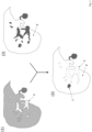
- a first step (10) at least one first MRI image (1) is provided, wherein the at least one first MRI image (1) shows a liver or part of a liver of an examination subject, wherein blood vessels in the liver are shown in a contrast-enhanced (signal-enhanced) manner by a contrast agent.
- a contrast-enhanced signal-enhanced
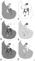
- This can, for example, be the Fig. 1 (d) shown MRI image.
- the at least one first MRI image (1) shows venous blood vessels as particularly bright (signal-enhanced) compared to other tissue due to the contrast agent present in the veins at the time the MRI image was measured. Those areas within the at least one first MRI image that are shown as "particularly bright” can therefore be traced back to venous blood vessels.
- these areas shown as "particularly bright" in the at least one first MRI image are identified. This is preferably done using the tonal values of the pixels or voxels of the areas. If the tonal value of a pixel or voxel is above a lower tonal value threshold and below an upper tonal value threshold, i.e. within a defined first tonal value band, it can be assumed that the corresponding pixel or voxel represents part of a venous blood vessel.
- the first tonal value band i.e. the lower and upper tonal values
- a radiologist can specify the structures in an MRI image that can be traced back to blood vessels. The tonal values of these structures can then define the tonal value band.
- those areas in the at least one first MRI image that have a tonal value within a defined (first) tonal value band are identified.
- a native MRI image is subtracted from the at least one first MRI image (difference image creation).
- the difference image then only shows the structures that are enhanced by contrast agents - and in the case of the at least one first MRI image, these are blood vessels.
- At least one second MRI image (2) is provided, wherein the at least one second MRI image shows the same liver or the same part of the liver as the at least one first MRI image, wherein the healthy liver tissue (parenchyma) is shown in a contrast-enhanced manner by a contrast agent.
- a contrast agent This can, for example, be the Fig. 1 (f) shown MRI image.
- those areas that represent healthy liver cells can be identified. This can be done analogously to the procedure in step (11), i.e. those pixels or voxels in the at least one second MRI image are identified whose tonal value is above a lower tonal value threshold and below an upper tonal value threshold, i.e. within a defined second tonal value band.
- the second tonal value band i.e. the lower and upper tonal values
- a difference image can also be created here (second MRI image minus native image).
- the difference image only shows the structures that are enhanced by contrast agents - and in the case of at least one second MRI image, these are healthy liver cells.
- a tone value is determined.
- This tone value is also referred to here as the liver tone value.
- the tone values of the pixels or voxels representing venous blood vessels in the at least one first MRI image are set to the liver tone value.
- the tone values of the pixels or voxels that represent healthy liver cells in at least one second MRI image are additionally set to the (averaged) liver tone value.
- the at least one first MRI image and the at least one second MRI image are at least partially superimposed.
- “Superimposing” or “overlaying” refers to the combination of the at least one first MRI image and the at least one second MRI image to form at least one third MRI image.
- the superimposition is usually carried out pixel by pixel or voxel by voxel for a pair of a first MRI image and a second MRI image. If the object under examination has not moved during the recording of the first and second MRI images, a pixel or voxel of the first MRI image corresponds exactly to a pixel or voxel of the second MRI image: the corresponding pixels or voxels show the same examination area at different times.
- some pixels or voxels of the first MRI image can be used as pixels or voxels of the third MRI image and some pixels or voxels of the second MRI image can be used as pixels or voxels of the third MRI image.
- the tonal values of some pixels or voxels of the first MRI image are mathematically linked to the corresponding pixels or voxels of the second MRI image: for example, (normalized) sum or difference images can be generated. It is crucial that the contrast difference between areas that are attributable to blood vessels and areas that are attributable to healthy liver cells is leveled out in the third MRI image.
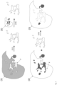
- a first three-dimensional MRI image (1) is provided, wherein the at least one first three-dimensional MRI image shows a liver or a part of a liver of an examination subject, wherein blood vessels in the liver are shown in a contrast-enhanced manner by a contrast agent.
- a second three-dimensional MRI image (2) is provided, wherein the second three-dimensional MRI image shows the same liver or the same part of the liver as the first three-dimensional MRI image, wherein the healthy liver tissue (parenchyma) is shown contrast-enhanced by a contrast agent.
- the tone values of the voxels representing healthy liver cells in the second three-dimensional MRI image are also set to the (averaged) liver tone value.
- the first three-dimensional MRI image and the second three-dimensional MRI image are combined in a third three-dimensional MRI image.
- the blood vessels segmented from the first three-dimensional MRI image are inserted into the second three-dimensional MRI image with the liver tone value, where the respective voxels of the first three-dimensional MRI image replace the corresponding voxels of the second three-dimensional MRI image. If necessary, a motion correction must be carried out. Since the voxels representing blood vessels are set to the liver tone value, the contrast difference between the areas of the third MRI image representing blood vessels and the areas of the third MRI image representing healthy liver cells is leveled out.
- a second MRI image (2) is provided, the second MRI image showing the same liver or part of the liver as the first MRI image, with the healthy liver tissue (parenchyma) shown contrast-enhanced (signal-enhanced) by a contrast agent.
- the first MRI image (1) and the second MRI image (2) are fed into a prediction model (PM).
- a first reference MRI image is accordingly an MRI image that shows a liver or part of a liver of an examination subject, wherein blood vessels in the liver are shown with contrast enhancement by a contrast agent;
- a second reference MRI image is accordingly an MRI image that shows the same liver or the same part of the liver as the first reference MRI image, wherein the healthy liver tissue (parenchyma) is shown with contrast enhancement by a contrast agent;
- a third reference MRI image is accordingly a combination according to the invention of a first and a second reference MRI image, in which the contrast difference between structures that are attributable to blood vessels and structures that are attributable to healthy liver cells is leveled.
- the self-learning algorithm creates a statistical model based on the training data. This means that the examples are not simply learned by heart, but the algorithm "recognizes" patterns and regularities in the training data. This enables the algorithm to evaluate unknown data. Validation data can be used to test the quality of the evaluation of unknown data.
- the self-learning algorithm is trained using supervised learning, i.e. the algorithm is presented with first and second reference MRI images and is told which third reference MRI images are associated with the respective first and second reference MRI images. The algorithm then learns a relationship between the reference MRI images in order to predict (calculate) third MRI images for unknown first and second MRI images.
- the prediction model is an artificial neural network.
- Such an artificial neural network comprises at least three layers of processing elements: a first layer with input neurons (nodes), an Nth layer with at least one output neuron (node), and N-2 inner layers, where N is a natural number and greater than 2.
- the input neurons are used to receive digital MRI images as input values. There is usually one input neuron for each pixel or voxel of a digital MRI image. There may be additional input neurons for additional input values (e.g. information about the examination area, the object under examination and/or the conditions that prevailed when the MRI images were generated).
- the output neurons serve to generate a first and a second MRI image and a third MRI image.
- the processing elements of the layers between the input neurons and the output neurons are connected in a predetermined pattern with predetermined connection weights.
- the artificial neural network is a so-called convolutional neural network (CNN for short).
- CNN convolutional neural network
- a convolutional neural network is able to process input data in the form of a matrix. This makes it possible to use digital MRI images presented as a matrix (e.g. width x height x color channels) as input data.
- a normal neural network e.g. in the form of a multi-layer perceptron (MLP), on the other hand, requires a vector as input, i.e. in order to use an MRI image as input, the pixels or voxels of the MRI image would have to be rolled out one after the other in a long chain. This means that normal neural networks are not able to recognize objects in an MRI image regardless of the position of the object in the MRI image. The same object at a different position in the MRI image would have a completely different input vector.
- MLP multi-layer perceptron
- a CNN essentially consists of filters (convolutional layer) and aggregation layers (pooling layer), which repeat alternately, and at the end of one or more layers of "normal" fully connected neurons (dense / fully connected layer).
- the neural network can be trained using a backpropagation method, for example.
- the aim is to achieve the most reliable mapping possible from given input vectors to given output vectors.
- the quality of the mapping is described by an error function.
- the aim is to minimize the error function.
- the backpropagation method is used to train an artificial neural network by changing the connection weights.
- connection weights between the processing elements contain information regarding the relationship between the first and second reference MRI images and the third reference MRI images, which can be used to predict one or more third MRI images based on new first and second MRI images.
- a cross-validation method can be used to split the data into training and validation sets.
- the training set is used in backpropagation training of the network weights.
- the validation set is used to check the prediction accuracy of the trained network when applied to unknown MRI images.
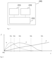
- FIG. 7 shows schematically a preferred embodiment of the system according to the invention.
- the system (30) comprises a receiving unit (31), a control and computing unit (32) and an output unit (33).
- the control and computing unit (32) is configured to cause the receiving unit (32) to receive at least a first MRI image of an examination object, wherein the at least a first MRI image shows a liver or part of a liver of the examination subject, with blood vessels in the liver being shown with contrast enhancement by a contrast agent.
- the control and computing unit (32) is further configured to cause the receiving unit (32) to receive at least one second MRI image of an examination object, wherein the at least one second MRI image shows the same liver or the same part of the liver in the hepatobiliary phase, wherein healthy liver cells are shown in a contrast-enhanced manner by a contrast agent.
- the control and computing unit (32) is further configured to generate at least one third MRI image by combining the at least one first MRI image and the at least one second MRI image and leveling the contrast difference between blood vessels and healthy liver cells.
- the control and computing unit (32) is further configured to cause the output unit to display, output or store the at least one third MRI image in a data memory.
- Figure 8 shows schematically the temporal course of the concentrations of contrast agent in the hepatic arteries (A), the hepatic veins (V) and the healthy liver cells (P) after an intravenous application of a hepatobiliary contrast agent as a bolus.
- the concentrations are shown in the form of the signal intensities I in the areas mentioned (hepatic arteries, hepatic veins, liver cells) during magnetic resonance measurement as a function of time t.
- the concentration of the contrast agent in the hepatic arteries (A) increases first (dashed curve). The concentration passes through a maximum and then decreases.
- the concentration in the hepatic veins (V) increases more slowly than in the hepatic arteries and reaches its maximum later (dotted curve).
- the concentration of the contrast agent in the healthy liver cells (P) increases slowly (solid curve) and only reaches its maximum at a much later point in time (the maximum is in the Figure 8 not shown).
- Several characteristic points in time can be defined: At time TP0, contrast medium is administered intravenously as a bolus. At time TP1, the concentration (signal intensity) of the contrast medium in the hepatic arteries reaches its maximum. At time TP2, the signal intensity curves at the hepatic arteries and the hepatic veins intersect.
- the concentration (signal intensity) of the contrast medium in the hepatic veins reaches its maximum.
- the signal intensity curves at the hepatic arteries and the liver cells intersect.
- the concentrations in the hepatic arteries and the hepatic veins have fallen to a level at which they no longer cause measurable contrast enhancement.
- the at least one first MRI image is an MRI image that was generated in the time period between TP0 and TP5, preferably between TP0 and TP4.
- at least two first MRI images are used to calculate the at least one third MRI image, preferably an MRI image that was generated in the time period between TP0 and TP3 and a further MRI image that was generated in the time period between TP2 and TP4.
- the at least one second MRI image is an MRI image that was generated according to TP5.
Landscapes
- Health & Medical Sciences (AREA)
- Physics & Mathematics (AREA)
- Engineering & Computer Science (AREA)
- Life Sciences & Earth Sciences (AREA)
- Nuclear Medicine, Radiotherapy & Molecular Imaging (AREA)
- General Health & Medical Sciences (AREA)
- Radiology & Medical Imaging (AREA)
- High Energy & Nuclear Physics (AREA)
- General Physics & Mathematics (AREA)
- Condensed Matter Physics & Semiconductors (AREA)
- Medical Informatics (AREA)
- Signal Processing (AREA)
- Animal Behavior & Ethology (AREA)
- Molecular Biology (AREA)
- Heart & Thoracic Surgery (AREA)
- Public Health (AREA)
- Veterinary Medicine (AREA)
- Biomedical Technology (AREA)
- Pathology (AREA)
- Biophysics (AREA)
- Surgery (AREA)
- Gastroenterology & Hepatology (AREA)
- Computer Vision & Pattern Recognition (AREA)
- Physiology (AREA)
- Endocrinology (AREA)
- Quality & Reliability (AREA)
- Theoretical Computer Science (AREA)
- Artificial Intelligence (AREA)
- Magnetic Resonance Imaging Apparatus (AREA)
- Medicines Containing Antibodies Or Antigens For Use As Internal Diagnostic Agents (AREA)
Claims (14)
- Procédé mis en œuvre par ordinateur, comprenant les étapes suivantes- recevoir au moins une première image IRM (1) d'un objet à examiner, ladite au moins une première image IRM (1) montrant un foie ou une partie d'un foie du objet à examiner, des vaisseaux sanguins (A, V) du foie étant représentés avec un contraste renforcé par un agent de contraste hépatobiliaire,- recevoir au moins une deuxième image IRM (2) du même objet à examiner, ladite au moins une deuxième image IRM (2) montrant le même foie ou la même partie du foie dans la phase hépatobiliaire, des cellules hépatiques saines (P) étant représentées avec un contraste renforcé par l'agent de contraste hépatobiliaire,caractérisé en ce que le procédé comprend en outre les étapes suivantes :- générer au moins une troisième image IRM (3) en combinant ladite au moins une première image IRM (1) avec ladite au moins une deuxième image IRM (2) et en nivelant la différence de contraste entre les vaisseaux sanguins (A, V) représentés avec un contraste renforcé dans ladite au moins une première image IRM (1) et les cellules hépatiques saines (P) représentées avec un contraste renforcé dans ladite au moins une deuxième image IRM (2),- afficher et/ou fournir en sortie ladite au moins une troisième image IRM (3) et/ou mémoriser ladite au moins une troisième image IRM (3) dans une mémoire de données.
- Procédé selon la revendication 1, dans lequel ladite au moins une première image IRM (1) est une représentation pondérée en T1 du foie ou de la partie du foie dans une phase veineuse après application d'un agent de contraste paramagnétique hépatobiliaire.
- Procédé selon la revendication 1 ou 2, dans lequel ladite au moins une deuxième image IRM (2) est une représentation pondérée en T1 du foie ou de la partie du foie dans la phase veineuse après application d'un agent de contraste paramagnétique hépatobiliaire.
- Procédé selon l'une des revendications 1 à 3, dans lequel l'agent de contraste est une substance ou un mélange de substances contenant de l'acide gadoxétique ou un sel de l'acide gadoxétique en tant qu'agent de renforcement du contraste, de préférence du Gd-EOB-DTPA disodique.
- Procédé selon l'une des revendications 1 à 4, dans lequel l'étape de génération d'au moins une troisième image IRM (3) comprend les sous-étapes suivantes :- identifier des zones dans ladite au moins une première image IRM (1) qui représentent des vaisseaux sanguins (A, V) en identifiant les pixels ou voxels de ladite au moins une première image IRM (1) qui présentent une valeur tonale se situant à l'intérieur d'une première bande de valeurs tonales définie, et/ou- identifier des zones dans ladite au moins une deuxième image IRM (2) qui représentent des cellules hépatiques saines (P) en identifiant les pixels ou voxels de ladite au moins une deuxième image IRM (2) qui présentent une valeur tonale se situant à l'intérieur d'une deuxième bande de valeurs tonales définie, et- superposer au moins partiellement ladite au moins une première image IRM (1) et ladite au moins une deuxième image IRM (2) et ainsi, générer ladite au moins une troisième image IRM (3), les valeurs tonales des pixels ou voxels dont la valeur tonale se situe à l'intérieur de la première largeur de bande définie et des pixels ou voxels dont la valeur tonale se situe à l'intérieur de la deuxième largeur de bande définie étant réglées à une valeur tonale commune dans ladite au moins une troisième image IRM (3).
- Procédé selon l'une des revendications 1 à 4, dans lequel l'étape de génération d'au moins une troisième image IRM (3) comprend les sous-étapes suivantes :- identifier les vaisseaux sanguins (A, V) dans ladite au moins une première image IRM (1) au moyen d'un procédé de segmentation,- identifier les structures dans ladite au moins une deuxième image IRM (2) qui correspondent aux vaisseaux sanguins (A, V) dans ladite au moins une première image IRM (1),- identifier une valeur tonale de cellules hépatiques saines (P) dans ladite au moins une deuxième image IRM (2),- régler les valeurs tonales des structures dans ladite au moins une deuxième image IRM (2) qui correspondent aux vaisseaux sanguins (A, V) dans ladite au moins une première image IRM (1) à la valeur tonale des cellules hépatiques saines (P).
- Procédé selon l'une des revendications 1 à 4, dans lequel l'étape de génération d'au moins une troisième image IRM (3) comprend les sous-étapes suivantes :- fournir ladite au moins une première image IRM (1) et ladite au moins une deuxième image IRM (2) à un modèle de prédiction (PM), le modèle de prédiction (PM) ayant été entraîné par apprentissage supervisé sur la base d'images IRM de référence, pour générer au moins une troisième image IRM de référence à partir d'au moins une première image IRM de référence et d'au moins une deuxième image IRM de référence, la différence de contraste entre des structures attribuables aux vaisseaux sanguins (A, V) et des structures attribuables aux cellules hépatiques saines (P) étant nivelée dans ladite au moins une troisième image IRM de référence,- recevoir au moins une troisième image IRM (3) en tant que sortie du modèle de prédiction (PM).
- Procédé selon la revendication 7, dans lequel le modèle de prédiction (PM) est un réseau neuronal artificiel.
- Système (30) comprenant• une unité de réception (31),• une unité de commande et de calcul (32) et• une unité de sortie (33),- dans lequel l'unité de commande et de calcul (32) est configurée pour amener l'unité de réception (31) à recevoir au moins une première image IRM (1) d'un objet à examiner, ladite au moins une première image IRM (1) montrant un foie ou une partie d'un foie du objet à examiner, des vaisseaux sanguins (A, V) du foie étant représentés avec un contraste renforcé par un agent de contraste hépatobiliaire,- dans lequel l'unité de commande et de calcul (32) est configurée pour amener l'unité de réception (31) à recevoir au moins une deuxième image IRM (2) d'un objet à examiner, ladite au moins une deuxième image IRM (2) montrant le même foie ou la même partie du foie dans la phase hépatobiliaire, des cellules hépatiques saines (P) étant représentées avec un contraste renforcé par l'agent de contraste hépatobiliaire,caractérisé en ce que- l'unité de commande et de calcul (32) est configurée pour∘ générer au moins une troisième image IRM (3) en combinant ladite au moins une première image IRM (1) et ladite au moins une deuxième image IRM (2) et en nivelant la différence de contraste entre les vaisseaux sanguins (A, V) représentés avec un contraste renforcé dans ladite au moins une première image IRM (1) et les cellules hépatiques saines (P) représentées avec un contraste renforcé dans ladite au moins une deuxième image IRM (2),o amener l'unité de sortie (33) à afficher, délivrer ou mémoriser dans une mémoire de données ladite au moins une troisième image IRM (3).
- Produit programme d'ordinateur comprenant un programme d'ordinateur qui peut être chargé dans une mémoire vive d'un système d'ordinateur et qui, dans celui-ci, amène le système d'ordinateur à mettre en œuvre les étapes suivantes :- recevoir au moins une première image IRM (1) d'un sujet à examiner, ladite au moins une première image IRM (1) montrant un foie ou une partie d'un foie du sujet à examiner, des vaisseaux sanguins (A, V) du foie étant représentés avec un contraste renforcé par un agent de contraste hépatobiliaire,- recevoir au moins une deuxième image IRM (2) du même objet à examiner, ladite au moins une deuxième image IRM (2) montrant le même foie ou la même partie du foie dans la phase hépatobiliaire, des cellules hépatiques saines (P) étant représentées avec un contraste renforcé par l'agent de contraste hépatobiliaire,caractérisé en ce que le programme d'ordinateur amène en outre le système d'ordinateur à effectuer les étapes suivantes :- générer au moins une troisième image IRM (3) en combinant ladite au moins une première image IRM (1) avec ladite au moins une deuxième image IRM (2) et en nivelant la différence de contraste entre les vaisseaux sanguins (A, V) représentés avec un contraste renforcé dans ladite au moins une première image IRM (1) et les cellules hépatiques saines (P) représentées avec un contraste renforcé dans ladite au moins une deuxième image IRM (2),- afficher et/ou fournir en sortie ladite au moins une troisième image IRM (3) et/ou mémoriser ladite au moins une troisième image IRM (3) dans une mémoire de données.
- Produit programme d'ordinateur selon la revendication 10, dans lequel le programme d'ordinateur amène le système d'ordinateur à mettre en œuvre une ou plusieurs des étapes mentionnées dans les revendications 2 à 8.
- Utilisation d'un agent de contraste hépatobiliaire dans un procédé d'IRM, le procédé d'IRM comprenant les étapes suivantes :- appliquer l'agent de contraste, l'agent de contraste se répartissant dans le foie d'un objet à examiner,- générer au moins une première image IRM (1), ladite au moins une première image IRM (1) montrant le foie ou une partie du foie du objet à examiner, des vaisseaux sanguins (A, V) du foie étant représentés avec un contraste renforcé par l'agent de contraste,- générer au moins une deuxième image IRM (2), ladite au moins une deuxième image IRM (2) montrant le même foie ou la même partie du foie dans la phase hépatobiliaire, des cellules hépatiques saines (P) étant représentées avec un contraste renforcé par l'agent de contraste,caractérisé en ce que le procédé d'IRM comprend en outre les étapes suivantes :- générer au moins une troisième image IRM (3) en combinant ladite au moins une première image IRM (1) avec ladite au moins une deuxième image IRM (2) et en nivelant la différence de contraste entre les vaisseaux sanguins (A, V) représentés avec un contraste renforcé dans ladite au moins une première image IRM (1) et les cellules hépatiques saines (P) représentées avec un contraste renforcé dans ladite au moins une deuxième image IRM (2),- afficher et/ou fournir en sortie ladite au moins une troisième image IRM (3) et/ou mémoriser ladite au moins une troisième image IRM (3) dans une mémoire de données.
- Kit comprenant un agent de contraste d'IRM hépatobiliaire et un produit programme d'ordinateur selon la revendication 10 ou 11.
- Kit selon la revendication 13, dans lequel l'agent de contraste d'IRM est une substance ou un mélange de substances contenant de l'acide gadoxétique ou un sel de l'acide gadoxétique en tant qu'agent de renforcement du contraste, de préférence du Gd-EOB-DTPA disodique.
Applications Claiming Priority (2)
| Application Number | Priority Date | Filing Date | Title |
|---|---|---|---|
| EP19197986 | 2019-09-18 | ||
| PCT/EP2020/075288 WO2021052850A1 (fr) | 2019-09-18 | 2020-09-10 | Génération d'images irm du foie |
Publications (2)
| Publication Number | Publication Date |
|---|---|
| EP4031893A1 EP4031893A1 (fr) | 2022-07-27 |
| EP4031893B1 true EP4031893B1 (fr) | 2024-12-25 |
Family
ID=68084580
Family Applications (1)
| Application Number | Title | Priority Date | Filing Date |
|---|---|---|---|
| EP20771810.7A Active EP4031893B1 (fr) | 2019-09-18 | 2020-09-10 | Génération d'enregistrements irm du foie |
Country Status (7)
| Country | Link |
|---|---|
| US (1) | US12310741B2 (fr) |
| EP (1) | EP4031893B1 (fr) |
| JP (1) | JP2022548716A (fr) |
| CN (1) | CN114402215A (fr) |
| AU (1) | AU2020347774A1 (fr) |
| CA (1) | CA3154650A1 (fr) |
| WO (1) | WO2021052850A1 (fr) |
Families Citing this family (8)
| Publication number | Priority date | Publication date | Assignee | Title |
|---|---|---|---|---|
| EP3939003B1 (fr) | 2019-03-12 | 2024-04-03 | Bayer HealthCare, LLC | Systèmes et procédés permettant d'évaluer une probabilité de cteph et d'identifier des caractéristiques indiquant celle-ci |
| JP7535575B2 (ja) | 2019-09-18 | 2024-08-16 | バイエル、アクチエンゲゼルシャフト | 組織特性を予測、予想、および/または査定するためのシステム、方法、およびコンピュータプログラム製品 |
| US12310741B2 (en) | 2019-09-18 | 2025-05-27 | Bayer Aktiengesellschaft | Generation of MRI images of the liver |
| EP4231037A1 (fr) | 2019-09-18 | 2023-08-23 | Bayer Aktiengesellschaft | Accélération d'examens irm |
| WO2021197996A1 (fr) | 2020-04-03 | 2021-10-07 | Bayer Aktiengesellschaft | Génération d'images radiologiques |
| JP2022149625A (ja) * | 2021-03-25 | 2022-10-07 | キヤノンメディカルシステムズ株式会社 | 医用画像診断システムおよび画像処理プログラム |
| KR102660268B1 (ko) * | 2021-11-18 | 2024-04-25 | 재단법인 아산사회복지재단 | 동적 영상데이터 기반 대상체 상태 예측 방법 및 이를 수행하는 컴퓨팅 장치 |
| CN118078249B (zh) * | 2024-04-23 | 2024-11-29 | 中国医学科学院阜外医院 | 心脏磁共振成像水脂分离的方法 |
Family Cites Families (102)
| Publication number | Priority date | Publication date | Assignee | Title |
|---|---|---|---|---|
| US732697A (en) | 1903-02-19 | 1903-07-07 | John Davis Bates | Lumber-surface meter. |
| US6039931A (en) | 1989-06-30 | 2000-03-21 | Schering Aktiengesellschaft | Derivatized DTPA complexes, pharmaceutical agents containing these compounds, their use, and processes for their production |
| US6397098B1 (en) | 1994-09-21 | 2002-05-28 | Medrad, Inc. | Data communication and control for medical imaging systems |
| US5840026A (en) | 1994-09-21 | 1998-11-24 | Medrad, Inc. | Patient specific dosing contrast delivery systems and methods |
| US5732697A (en) | 1995-11-22 | 1998-03-31 | Arch Development Corporation | Shift-invariant artificial neural network for computerized detection of clustered microcalcifications in mammography |
| US5855868A (en) * | 1996-04-01 | 1999-01-05 | Nycomed Imaging As | Method of T1 -weighted resonance imaging of RES organs |
| US6339718B1 (en) | 1999-07-30 | 2002-01-15 | Medrad, Inc. | Programmable injector control |
| US6754376B1 (en) | 2000-11-22 | 2004-06-22 | General Electric Company | Method for automatic segmentation of medical images |
| US6819790B2 (en) | 2002-04-12 | 2004-11-16 | The University Of Chicago | Massive training artificial neural network (MTANN) for detecting abnormalities in medical images |
| US7458936B2 (en) | 2003-03-12 | 2008-12-02 | Siemens Medical Solutions Usa, Inc. | System and method for performing probabilistic classification and decision support using multidimensional medical image databases |
| US7545965B2 (en) | 2003-11-10 | 2009-06-09 | The University Of Chicago | Image modification and detection using massive training artificial neural networks (MTANN) |
| WO2006093523A2 (fr) | 2004-07-15 | 2006-09-08 | Kenji Suzuki | Programme informatique permettant de distinguer entre des nodules benins et des nodules malins par tacographie thoracique realisee a faible dose |
| WO2006055813A2 (fr) | 2004-11-16 | 2006-05-26 | Medrad, Inc. | Modelage de propagation pharmaceutique |
| US7738683B2 (en) | 2005-07-22 | 2010-06-15 | Carestream Health, Inc. | Abnormality detection in medical images |
| US7564990B2 (en) | 2005-08-18 | 2009-07-21 | Nu Skin International, Inc. | Imaging system and method for physical feature analysis |
| US7343032B2 (en) | 2005-09-01 | 2008-03-11 | Fujifilm Corporation | Method and apparatus for automatic and dynamic vessel detection |
| EP1780677A1 (fr) | 2005-10-25 | 2007-05-02 | BRACCO IMAGING S.p.A. | Tête de lecture pour dispositif de mesure |
| US7840044B2 (en) | 2005-11-01 | 2010-11-23 | Edda Technology Inc. | Method and system for liver lobe segmentation and pre-operative surgical planning |
| US20220031270A1 (en) | 2007-03-08 | 2022-02-03 | Sync-Rx, Ltd | Identification an dpresentation of device-tovessel relative motion |
| US9370316B2 (en) | 2007-05-18 | 2016-06-21 | Henry Ford Health System | MRI estimation of contrast agent concentration using a neural network approach |
| DE102007028660B3 (de) | 2007-06-21 | 2009-01-29 | Siemens Ag | Verfahren zur Korrektur von Bewegungsartefakten bei der Aufnahme von MR-Bildern |
| WO2009098627A1 (fr) | 2008-02-07 | 2009-08-13 | Koninklijke Philips Electronics N.V. | Dispositif pour mesurer et prédire la stabilité respiratoire d'un patient |
| WO2009135923A1 (fr) | 2008-05-08 | 2009-11-12 | Oslo Universitetssykehus Hf | Segmentation de vaisseaux en imagerie rm à amélioration dynamique du contraste (dce) |
| US7949167B2 (en) | 2008-06-12 | 2011-05-24 | Siemens Medical Solutions Usa, Inc. | Automatic learning of image features to predict disease |
| EP2528493B1 (fr) | 2010-01-28 | 2017-04-19 | Brainlab AG | Procédé et appareil destinés à estimer la température dans un corps |
| US8478698B1 (en) | 2010-03-17 | 2013-07-02 | James Mah | Methods and systems for employing artificial intelligence in automated orthodontic diagnosis and treatment planning |
| RU2725751C9 (ru) | 2010-12-08 | 2020-12-21 | БАЙЕР ХелсКер ЛЛСи | Создание подходящей модели для оценки дозы облучения пациента в результате сканирований для медицинской визуализации |
| FR2979453B1 (fr) | 2011-08-26 | 2016-01-08 | Olea Medical | Systeme et procede pour estimer une quantite d'interet d'un systeme dynamique artere/tissu/veine |
| WO2013036842A2 (fr) | 2011-09-08 | 2013-03-14 | Radlogics, Inc. | Procédés et systèmes pour analyser des images médicales et faire un compte-rendu sur celles-ci |
| JP5878009B2 (ja) | 2011-12-12 | 2016-03-08 | 株式会社根本杏林堂 | 医療用画像処理ネットワークシステム |
| WO2016007734A1 (fr) | 2014-07-09 | 2016-01-14 | The Trustees Of Dartmouth College | Procédés pour une imagerie médicale moléculaire quantitative et à contraste amélioré utilisant une correction inter-modalités pour une cinétique de traceur différente |
| EP2626718A1 (fr) | 2012-02-09 | 2013-08-14 | Koninklijke Philips Electronics N.V. | IRM avec correction de mouvement utilisant des navigateurs acquis avec une technique de Dixon |
| RU2629799C2 (ru) | 2012-02-17 | 2017-09-04 | Конинклейке Филипс Н.В. | Оценка и наблюдение острого повреждения легких (ali)/синдрома острой дыхательной недостаточности (ards) |
| WO2013169353A1 (fr) | 2012-05-11 | 2013-11-14 | University Of Iowa Research Foundation | Méthodes d'imagerie multimodale mettant en oeuvre des nanoparticules de silice mésoporeuses |
| DE102012215718B4 (de) | 2012-09-05 | 2022-05-12 | Siemens Healthcare Gmbh | Verfahren und Magnetresonanzanlage zur MR-Bildgebung eines vorbestimmten Volumenabschnitts eines lebenden Untersuchungsobjekts mittels Stimulieren des Untersuchungsobjekts |
| US9449381B2 (en) | 2012-09-10 | 2016-09-20 | Arizona Board Of Regents, A Body Corporate Of The State Of Arizona, Acting For And On Behalf Of Arizona State University | Methods, systems, and media for generating and analyzing medical images having elongated structures |
| WO2014068520A1 (fr) | 2012-10-31 | 2014-05-08 | Koninklijke Philips N.V. | Imagerie de perfusion |
| EP2750102B2 (fr) | 2012-12-27 | 2025-12-10 | General Electric Company | Procédé, système et support lisible par ordinateur pour l'analyse du foie |
| US9901650B2 (en) | 2013-02-21 | 2018-02-27 | University Of Rochester | Methods for evaluating brain-wide paravascular pathway for waste clearance function and methods for treating neurodegenerative disorders based thereon |
| US10089744B2 (en) | 2013-04-03 | 2018-10-02 | Koninklijke Philips N.V. | Vessel segmentation |
| CN103218788B (zh) * | 2013-04-24 | 2015-12-02 | 南方医科大学 | 一种肝脏磁共振r2*参数的测量方法 |
| EP2988668B1 (fr) | 2013-04-24 | 2019-07-24 | Tel HaShomer Medical Research Infrastructure and Services Ltd. | Cartes de résonance magnétique pour analyse de tissu |
| WO2016019347A1 (fr) | 2014-07-31 | 2016-02-04 | California Institute Of Technology | Système de cartographie cérébrale à modalités multiples (mbms) utilisant une intelligence artificielle et une reconnaissance des formes |
| US20160038092A1 (en) | 2014-08-11 | 2016-02-11 | Douglas A. Golay | Applying non-real time and non-user attended algorithms to stored non-imaging data and existing imaging data for obtaining a dental diagnosis |
| US10061003B2 (en) | 2014-09-01 | 2018-08-28 | bioProtonics, L.L.C. | Selective sampling for assessing structural spatial frequencies with specific contrast mechanisms |
| US10176573B2 (en) | 2014-10-13 | 2019-01-08 | Agency For Science, Technology And Research | Automatic region-of-interest segmentation and registration of dynamic contrast-enhanced images of colorectal tumors |
| WO2016084373A1 (fr) | 2014-11-27 | 2016-06-02 | 国立大学法人広島大学 | Simulateur, dispositif d'injection ou système d'imagerie doté d'un simulateur, et programme de simulation |
| JP2018511791A (ja) | 2015-02-27 | 2018-04-26 | バイエル・ヘルスケア・エルエルシーBayer HealthCare LLC | マルチイメージングモダリティ用定量的ファントム |
| US9959615B2 (en) | 2015-07-01 | 2018-05-01 | Arizona Board Of Regents On Behalf Of Arizona State University | System and method for automatic pulmonary embolism detection |
| US20170016972A1 (en) | 2015-07-13 | 2017-01-19 | Siemens Medical Solutions Usa, Inc. | Fast Prospective Motion Correction For MR Imaging |
| US10634753B2 (en) | 2015-07-15 | 2020-04-28 | Koninklijke Philips N.V. | MR imaging with motion detection |
| US10157467B2 (en) | 2015-08-07 | 2018-12-18 | Arizona Board Of Regents On Behalf Of Arizona State University | System and method for detecting central pulmonary embolism in CT pulmonary angiography images |
| US10176408B2 (en) | 2015-08-14 | 2019-01-08 | Elucid Bioimaging Inc. | Systems and methods for analyzing pathologies utilizing quantitative imaging |
| WO2017035097A1 (fr) | 2015-08-21 | 2017-03-02 | Duke University | Systèmes et procédés pour déterminer une qualité d'image et des modèles sur la base de protocoles d'injection d'agent de contraste |
| DK3341048T3 (da) | 2015-08-28 | 2023-08-21 | Bayer Healthcare Llc | System og fremgangsmåde til verificering af sprøjtefluidfyldning og billedgenkendelse af træk ved kraftinjektorsystem |
| US10645359B2 (en) | 2015-12-16 | 2020-05-05 | B<>Com | Method for processing a digital image, device, terminal equipment and associated computer program |
| US9786058B2 (en) | 2016-02-08 | 2017-10-10 | Sony Corporation | Method and system for segmentation of vascular structure in a volumetric image dataset |
| US20170245817A1 (en) | 2016-02-10 | 2017-08-31 | The Charles Stark Draper Laboratory, Inc. | Systems and methods for imaging |
| DE102016204198B4 (de) | 2016-03-15 | 2018-06-07 | Siemens Healthcare Gmbh | Verfahren zur Erzeugung von MR-Bildern mit prospektiver Bewegungskorrektur und teilvolumenspezifischer Gewichtung der Bildinformation |
| US10282588B2 (en) | 2016-06-09 | 2019-05-07 | Siemens Healthcare Gmbh | Image-based tumor phenotyping with machine learning from synthetic data |
| WO2018048507A1 (fr) | 2016-09-06 | 2018-03-15 | Han Xiao | Réseau neuronal pour la génération d'images médicales de synthèse |
| US11544529B2 (en) | 2016-09-07 | 2023-01-03 | Koninklijke Philips N.V. | Semi-supervised classification with stacked autoencoder |
| AU2017345167B2 (en) | 2016-10-17 | 2022-12-15 | Bayer Healthcare Llc | Fluid injector with syringe engagement mechanism |
| US10933186B2 (en) | 2016-11-22 | 2021-03-02 | Bayer Healthcare Llc | System and method for delivering a fluid with a consistent total volumetric flowrate |
| CA3043038A1 (fr) | 2016-11-22 | 2018-05-31 | Hyperfine Research, Inc. | Systemes et procedes de detection automatisee dans des images a resonance magnetique |
| US10096109B1 (en) | 2017-03-31 | 2018-10-09 | The Board Of Trustees Of The Leland Stanford Junior University | Quality of medical images using multi-contrast and deep learning |
| JP7179757B2 (ja) | 2017-04-25 | 2022-11-29 | ザ ボード オブ トラスティーズ オブ ザ レランド スタンフォード ジュニア ユニバーシティー | ディープ畳み込みニューラルネットワークを使用した医用画像化のための線量低減 |
| US20180315183A1 (en) | 2017-04-28 | 2018-11-01 | General Electric Company | System and method for monitoring an amount of a contrast agent within an object |
| WO2018202541A1 (fr) | 2017-05-02 | 2018-11-08 | Bayer Aktiengesellschaft | Améliorations dans la détection radiologique de l'hypertension pulmonaire thromboembolique chronique |
| JP6920904B2 (ja) | 2017-07-04 | 2021-08-18 | 国立大学法人広島大学 | シミュレータ、該シミュレータを備える注入装置又は撮像システム、及びシミュレーションプログラム |
| AU2018323442B2 (en) | 2017-08-31 | 2024-06-27 | Bayer Healthcare Llc | Fluid path impedance assessment for improving fluid delivery performance |
| US11631485B2 (en) | 2017-09-26 | 2023-04-18 | Koninklijke Philips N.V. | System and method for joint clinical decision for pharmaceuticals |
| US10335106B2 (en) | 2017-09-29 | 2019-07-02 | Infinitt Healthcare Co., Ltd. | Computing system and method for identifying and visualizing cerebral thrombosis based on medical images |
| SG11202003232VA (en) | 2017-10-09 | 2020-05-28 | Univ Leland Stanford Junior | Contrast dose reduction for medical imaging using deep learning |
| US11100621B2 (en) | 2017-10-20 | 2021-08-24 | Imaging Biometrics, Llc | Simulated post-contrast T1-weighted magnetic resonance imaging |
| CN118866316A (zh) | 2017-10-31 | 2024-10-29 | 通用电气健康护理有限公司 | 用于诊断认知疾病病理和/或结果的医疗系统 |
| WO2019102846A1 (fr) | 2017-11-24 | 2019-05-31 | キヤノンメディカルシステムズ株式会社 | Dispositif de traitement de données médicales, dispositif d'imagerie par résonance magnétique et procédé de génération de modèle appris |
| CN108324244A (zh) | 2018-01-03 | 2018-07-27 | 华东师范大学 | 用于ai+mri影像辅助诊断的自动增广训练样本的构建方法及系统 |
| KR102001398B1 (ko) | 2018-01-25 | 2019-07-18 | 재단법인 아산사회복지재단 | 기계학습을 통한 뇌질환 상태변화 예측방법, 장치 및 프로그램 |
| WO2019161043A1 (fr) | 2018-02-15 | 2019-08-22 | GE Precision Healthcare LLC | Système et procédé pour synthétiser des images à résonance magnétique |
| WO2019183555A1 (fr) | 2018-03-22 | 2019-09-26 | The University Of North Carolina At Chapel Hill | Procédés, systèmes et supports lisibles par ordinateur en vue de traiter des images d'angiographie par soustraction numérique (dsa) et de tomodensitométrie (ct) en vue de réduire l'exposition au rayonnement chez des sujets soumis à une dsa et à une ct |
| US11100632B2 (en) | 2018-04-13 | 2021-08-24 | Elekta, Inc. | Image synthesis using adversarial networks such as for radiation therapy |
| US11982726B2 (en) | 2018-04-13 | 2024-05-14 | University Of Southern California | Method for joint arterial input function and tracer kinetic parameter estimation in accelerated DCE-MRI using a model consistency constraint |
| US20190347772A1 (en) | 2018-04-19 | 2019-11-14 | Subtle Medical, Inc. | Systems and methods for improving magnetic resonance imaging using deep learning |
| CN108703764B (zh) | 2018-05-29 | 2021-11-05 | 北京东软医疗设备有限公司 | 血管造影方法、装置、系统、设备及存储介质 |
| WO2019241659A1 (fr) | 2018-06-15 | 2019-12-19 | Subtle Medical, Inc. | Systèmes et méthodes de normalisation d'imagerie par résonance magnétique à l'aide d'un apprentissage profond |
| EP3649955A1 (fr) | 2018-11-07 | 2020-05-13 | Koninklijke Philips N.V. | Suivi de bolus spectral par moyen de deep learning |
| EP3657433B1 (fr) | 2018-11-22 | 2022-10-19 | Siemens Healthcare GmbH | Données d'images médicales |
| DE102018222606A1 (de) | 2018-12-20 | 2020-06-25 | Siemens Healthcare Gmbh | Verfahren und Vorrichtung zur Detektion eines anatomischen Merkmals eines Blutgefäßabschnittes |
| US10867375B2 (en) | 2019-01-30 | 2020-12-15 | Siemens Healthcare Gmbh | Forecasting images for image processing |
| US11398026B2 (en) | 2019-03-28 | 2022-07-26 | The Board Of Trustees Of The Leland Stanford Junior University | Systems and methods for synthetic medical image generation |
| DE102019207639A1 (de) | 2019-05-24 | 2020-11-26 | Siemens Healthcare Gmbh | Verbesserte Berechnung der Kontrastmittelkonzentration |
| EP3756547A1 (fr) | 2019-06-28 | 2020-12-30 | Koninklijke Philips N.V. | Analyse automatique de coronarographie |
| US20210012486A1 (en) | 2019-07-09 | 2021-01-14 | Shenzhen Malong Technologies Co., Ltd. | Image synthesis with generative adversarial network |
| CN110391016B (zh) | 2019-07-10 | 2021-11-09 | 浙江大学 | 一种动态对比增强磁共振图像的分析方法 |
| US12310741B2 (en) | 2019-09-18 | 2025-05-27 | Bayer Aktiengesellschaft | Generation of MRI images of the liver |
| EP4041075B1 (fr) | 2019-10-08 | 2025-08-13 | Bayer Aktiengesellschaft | Génération d'enregistrements irm du foie sans rehaussement du contraste |
| EP3804615A1 (fr) | 2019-10-08 | 2021-04-14 | Bayer AG | Génération d'enregistrements irm du foie |
| WO2021069343A1 (fr) | 2019-10-11 | 2021-04-15 | Bayer Aktiengesellschaft | Accélération d'examens irm |
| EP3875979A1 (fr) | 2020-03-06 | 2021-09-08 | Bayer Aktiengesellschaft | Procédé d'imagerie à résonance magnétique améliorée à contraste dynamique optimisé |
| WO2021197996A1 (fr) | 2020-04-03 | 2021-10-07 | Bayer Aktiengesellschaft | Génération d'images radiologiques |
| US11308613B2 (en) | 2020-06-09 | 2022-04-19 | Siemens Healthcare Gmbh | Synthesis of contrast enhanced medical images |
-
2020
- 2020-09-10 US US17/655,017 patent/US12310741B2/en active Active
- 2020-09-10 JP JP2022517512A patent/JP2022548716A/ja active Pending
- 2020-09-10 AU AU2020347774A patent/AU2020347774A1/en not_active Abandoned
- 2020-09-10 WO PCT/EP2020/075288 patent/WO2021052850A1/fr not_active Ceased
- 2020-09-10 CA CA3154650A patent/CA3154650A1/fr active Pending
- 2020-09-10 EP EP20771810.7A patent/EP4031893B1/fr active Active
- 2020-09-10 CN CN202080065186.2A patent/CN114402215A/zh active Pending
Non-Patent Citations (1)
| Title |
|---|
| ZHANG XUEJUN ET AL: "Application of an artificial neural network to the computer-aided differentiation of focal liver disease in MR imaging", RADIOLOGICAL PHYSICS AND TECHNOLOGY, SPRINGER JAPAN KK, JP, vol. 2, no. 2, 1 July 2009 (2009-07-01), pages 175 - 182, XP036001157, ISSN: 1865-0333, [retrieved on 20090701], DOI: 10.1007/S12194-009-0062-5 * |
Also Published As
| Publication number | Publication date |
|---|---|
| US12310741B2 (en) | 2025-05-27 |
| JP2022548716A (ja) | 2022-11-21 |
| CN114402215A (zh) | 2022-04-26 |
| US20230218223A1 (en) | 2023-07-13 |
| CA3154650A1 (fr) | 2021-03-25 |
| WO2021052850A1 (fr) | 2021-03-25 |
| EP4031893A1 (fr) | 2022-07-27 |
| AU2020347774A1 (en) | 2022-03-31 |
Similar Documents
| Publication | Publication Date | Title |
|---|---|---|
| EP4041075B1 (fr) | Génération d'enregistrements irm du foie sans rehaussement du contraste | |
| EP4031894B1 (fr) | Prédiction des images irm par modèle de prédiction formé par apprentissage supervisé | |
| WO2021052850A1 (fr) | Génération d'images irm du foie | |
| EP4143779B1 (fr) | Apprentissage automatique dans le domaine de la radiologie assistée par contraste | |
| EP4128261A1 (fr) | Génération d'images radiologiques | |
| WO2021069343A1 (fr) | Accélération d'examens irm | |
| EP3804615A1 (fr) | Génération d'enregistrements irm du foie | |
| EP4143784B1 (fr) | Apprentissage automatique dans le domaine de la radiologie assistée par contraste | |
| EP4334733B1 (fr) | Caractérisation des lésions dans le foie par résonance magnétique dynamique à contraste amélioré | |
| EP4483197B1 (fr) | Prédiction d'une représentation d'une zone d'examen d'un objet d'examen dans un état d'une séquence d'états | |
| EP4475137B1 (fr) | Génération d'enregistrements radiologiques artificiels à contraste amélioré | |
| EP4332601B1 (fr) | Génération d'enregistrements radiologiques artificiels renforcés par un agent de contraste | |
| EP4581640A1 (fr) | Génération d'images radiologiques de synthese | |
| EP4581641B1 (fr) | Production d'enregistrements radiologiques synthétiques | |
| EP4584603B1 (fr) | Accélération d'examens irm du foie | |
| EP4369285A1 (fr) | Génération d'enregistrements radiologiques artificiels renforcés par un agent de contraste | |
| DE102024208673A1 (de) | Verfahren zur Rekonstruktion einer Zeitreihe von Magnetresonanzdatensätzen zur Wasser-Fett Separierung basierend auf der Dixon Methode |
Legal Events
| Date | Code | Title | Description |
|---|---|---|---|
| STAA | Information on the status of an ep patent application or granted ep patent |
Free format text: STATUS: UNKNOWN |
|
| STAA | Information on the status of an ep patent application or granted ep patent |
Free format text: STATUS: THE INTERNATIONAL PUBLICATION HAS BEEN MADE |
|
| PUAI | Public reference made under article 153(3) epc to a published international application that has entered the european phase |
Free format text: ORIGINAL CODE: 0009012 |
|
| STAA | Information on the status of an ep patent application or granted ep patent |
Free format text: STATUS: REQUEST FOR EXAMINATION WAS MADE |
|
| 17P | Request for examination filed |
Effective date: 20220419 |
|
| AK | Designated contracting states |
Kind code of ref document: A1 Designated state(s): AL AT BE BG CH CY CZ DE DK EE ES FI FR GB GR HR HU IE IS IT LI LT LU LV MC MK MT NL NO PL PT RO RS SE SI SK SM TR |
|
| DAV | Request for validation of the european patent (deleted) | ||
| DAX | Request for extension of the european patent (deleted) | ||
| GRAP | Despatch of communication of intention to grant a patent |
Free format text: ORIGINAL CODE: EPIDOSNIGR1 |
|
| STAA | Information on the status of an ep patent application or granted ep patent |
Free format text: STATUS: GRANT OF PATENT IS INTENDED |
|
| INTG | Intention to grant announced |
Effective date: 20240424 |
|
| GRAJ | Information related to disapproval of communication of intention to grant by the applicant or resumption of examination proceedings by the epo deleted |
Free format text: ORIGINAL CODE: EPIDOSDIGR1 |
|
| STAA | Information on the status of an ep patent application or granted ep patent |
Free format text: STATUS: REQUEST FOR EXAMINATION WAS MADE |
|
| GRAP | Despatch of communication of intention to grant a patent |
Free format text: ORIGINAL CODE: EPIDOSNIGR1 |
|
| STAA | Information on the status of an ep patent application or granted ep patent |
Free format text: STATUS: GRANT OF PATENT IS INTENDED |
|
| GRAJ | Information related to disapproval of communication of intention to grant by the applicant or resumption of examination proceedings by the epo deleted |
Free format text: ORIGINAL CODE: EPIDOSDIGR1 |
|
| GRAP | Despatch of communication of intention to grant a patent |
Free format text: ORIGINAL CODE: EPIDOSNIGR1 |
|
| INTC | Intention to grant announced (deleted) | ||
| GRAJ | Information related to disapproval of communication of intention to grant by the applicant or resumption of examination proceedings by the epo deleted |
Free format text: ORIGINAL CODE: EPIDOSDIGR1 |
|
| STAA | Information on the status of an ep patent application or granted ep patent |
Free format text: STATUS: REQUEST FOR EXAMINATION WAS MADE |
|
| GRAP | Despatch of communication of intention to grant a patent |
Free format text: ORIGINAL CODE: EPIDOSNIGR1 |
|
| STAA | Information on the status of an ep patent application or granted ep patent |
Free format text: STATUS: GRANT OF PATENT IS INTENDED |
|
| GRAJ | Information related to disapproval of communication of intention to grant by the applicant or resumption of examination proceedings by the epo deleted |
Free format text: ORIGINAL CODE: EPIDOSDIGR1 |
|
| GRAJ | Information related to disapproval of communication of intention to grant by the applicant or resumption of examination proceedings by the epo deleted |
Free format text: ORIGINAL CODE: EPIDOSDIGR1 |
|
| GRAP | Despatch of communication of intention to grant a patent |
Free format text: ORIGINAL CODE: EPIDOSNIGR1 |
|
| STAA | Information on the status of an ep patent application or granted ep patent |
Free format text: STATUS: REQUEST FOR EXAMINATION WAS MADE |
|
| GRAP | Despatch of communication of intention to grant a patent |
Free format text: ORIGINAL CODE: EPIDOSNIGR1 |
|
| INTG | Intention to grant announced |
Effective date: 20240813 |
|
| STAA | Information on the status of an ep patent application or granted ep patent |
Free format text: STATUS: GRANT OF PATENT IS INTENDED |
|
| INTG | Intention to grant announced |
Effective date: 20240820 |
|
| INTC | Intention to grant announced (deleted) | ||
| INTG | Intention to grant announced |
Effective date: 20240903 |
|
| INTC | Intention to grant announced (deleted) | ||
| INTG | Intention to grant announced |
Effective date: 20240912 |
|
| GRAS | Grant fee paid |
Free format text: ORIGINAL CODE: EPIDOSNIGR3 |
|
| GRAA | (expected) grant |
Free format text: ORIGINAL CODE: 0009210 |
|
| STAA | Information on the status of an ep patent application or granted ep patent |
Free format text: STATUS: THE PATENT HAS BEEN GRANTED |
|
| AK | Designated contracting states |
Kind code of ref document: B1 Designated state(s): AL AT BE BG CH CY CZ DE DK EE ES FI FR GB GR HR HU IE IS IT LI LT LU LV MC MK MT NL NO PL PT RO RS SE SI SK SM TR |
|
| P01 | Opt-out of the competence of the unified patent court (upc) registered |
Free format text: CASE NUMBER: APP_61531/2024 Effective date: 20241118 |
|
| REG | Reference to a national code |
Ref country code: GB Ref legal event code: FG4D Free format text: NOT ENGLISH |
|
| REG | Reference to a national code |
Ref country code: CH Ref legal event code: EP |
|
| REG | Reference to a national code |
Ref country code: DE Ref legal event code: R096 Ref document number: 502020010064 Country of ref document: DE |
|
| REG | Reference to a national code |
Ref country code: IE Ref legal event code: FG4D Free format text: LANGUAGE OF EP DOCUMENT: GERMAN |
|
| REG | Reference to a national code |
Ref country code: LT Ref legal event code: MG9D |
|
| PG25 | Lapsed in a contracting state [announced via postgrant information from national office to epo] |
Ref country code: HR Free format text: LAPSE BECAUSE OF FAILURE TO SUBMIT A TRANSLATION OF THE DESCRIPTION OR TO PAY THE FEE WITHIN THE PRESCRIBED TIME-LIMIT Effective date: 20241225 |
|
| PG25 | Lapsed in a contracting state [announced via postgrant information from national office to epo] |
Ref country code: FI Free format text: LAPSE BECAUSE OF FAILURE TO SUBMIT A TRANSLATION OF THE DESCRIPTION OR TO PAY THE FEE WITHIN THE PRESCRIBED TIME-LIMIT Effective date: 20241225 |
|
| PG25 | Lapsed in a contracting state [announced via postgrant information from national office to epo] |
Ref country code: BG Free format text: LAPSE BECAUSE OF FAILURE TO SUBMIT A TRANSLATION OF THE DESCRIPTION OR TO PAY THE FEE WITHIN THE PRESCRIBED TIME-LIMIT Effective date: 20241225 |
|
| PG25 | Lapsed in a contracting state [announced via postgrant information from national office to epo] |
Ref country code: NO Free format text: LAPSE BECAUSE OF FAILURE TO SUBMIT A TRANSLATION OF THE DESCRIPTION OR TO PAY THE FEE WITHIN THE PRESCRIBED TIME-LIMIT Effective date: 20250325 |
|
| PG25 | Lapsed in a contracting state [announced via postgrant information from national office to epo] |
Ref country code: LV Free format text: LAPSE BECAUSE OF FAILURE TO SUBMIT A TRANSLATION OF THE DESCRIPTION OR TO PAY THE FEE WITHIN THE PRESCRIBED TIME-LIMIT Effective date: 20241225 Ref country code: GR Free format text: LAPSE BECAUSE OF FAILURE TO SUBMIT A TRANSLATION OF THE DESCRIPTION OR TO PAY THE FEE WITHIN THE PRESCRIBED TIME-LIMIT Effective date: 20250326 |
|
| PG25 | Lapsed in a contracting state [announced via postgrant information from national office to epo] |
Ref country code: RS Free format text: LAPSE BECAUSE OF FAILURE TO SUBMIT A TRANSLATION OF THE DESCRIPTION OR TO PAY THE FEE WITHIN THE PRESCRIBED TIME-LIMIT Effective date: 20250325 |
|
| REG | Reference to a national code |
Ref country code: NL Ref legal event code: MP Effective date: 20241225 |
|
| PG25 | Lapsed in a contracting state [announced via postgrant information from national office to epo] |
Ref country code: NL Free format text: LAPSE BECAUSE OF FAILURE TO SUBMIT A TRANSLATION OF THE DESCRIPTION OR TO PAY THE FEE WITHIN THE PRESCRIBED TIME-LIMIT Effective date: 20241225 |
|
| PG25 | Lapsed in a contracting state [announced via postgrant information from national office to epo] |
Ref country code: SM Free format text: LAPSE BECAUSE OF FAILURE TO SUBMIT A TRANSLATION OF THE DESCRIPTION OR TO PAY THE FEE WITHIN THE PRESCRIBED TIME-LIMIT Effective date: 20241225 |
|
| PG25 | Lapsed in a contracting state [announced via postgrant information from national office to epo] |
Ref country code: PL Free format text: LAPSE BECAUSE OF FAILURE TO SUBMIT A TRANSLATION OF THE DESCRIPTION OR TO PAY THE FEE WITHIN THE PRESCRIBED TIME-LIMIT Effective date: 20241225 |
|
| PG25 | Lapsed in a contracting state [announced via postgrant information from national office to epo] |
Ref country code: ES Free format text: LAPSE BECAUSE OF FAILURE TO SUBMIT A TRANSLATION OF THE DESCRIPTION OR TO PAY THE FEE WITHIN THE PRESCRIBED TIME-LIMIT Effective date: 20241225 |
|
| PG25 | Lapsed in a contracting state [announced via postgrant information from national office to epo] |
Ref country code: IS Free format text: LAPSE BECAUSE OF FAILURE TO SUBMIT A TRANSLATION OF THE DESCRIPTION OR TO PAY THE FEE WITHIN THE PRESCRIBED TIME-LIMIT Effective date: 20250425 |
|
| PG25 | Lapsed in a contracting state [announced via postgrant information from national office to epo] |
Ref country code: PT Free format text: LAPSE BECAUSE OF FAILURE TO SUBMIT A TRANSLATION OF THE DESCRIPTION OR TO PAY THE FEE WITHIN THE PRESCRIBED TIME-LIMIT Effective date: 20250428 |
|
| PG25 | Lapsed in a contracting state [announced via postgrant information from national office to epo] |
Ref country code: EE Free format text: LAPSE BECAUSE OF FAILURE TO SUBMIT A TRANSLATION OF THE DESCRIPTION OR TO PAY THE FEE WITHIN THE PRESCRIBED TIME-LIMIT Effective date: 20241225 |
|
| PG25 | Lapsed in a contracting state [announced via postgrant information from national office to epo] |
Ref country code: RO Free format text: LAPSE BECAUSE OF FAILURE TO SUBMIT A TRANSLATION OF THE DESCRIPTION OR TO PAY THE FEE WITHIN THE PRESCRIBED TIME-LIMIT Effective date: 20241225 |
|
| PG25 | Lapsed in a contracting state [announced via postgrant information from national office to epo] |
Ref country code: SK Free format text: LAPSE BECAUSE OF FAILURE TO SUBMIT A TRANSLATION OF THE DESCRIPTION OR TO PAY THE FEE WITHIN THE PRESCRIBED TIME-LIMIT Effective date: 20241225 |
|
| PG25 | Lapsed in a contracting state [announced via postgrant information from national office to epo] |
Ref country code: CZ Free format text: LAPSE BECAUSE OF FAILURE TO SUBMIT A TRANSLATION OF THE DESCRIPTION OR TO PAY THE FEE WITHIN THE PRESCRIBED TIME-LIMIT Effective date: 20241225 |
|
| PG25 | Lapsed in a contracting state [announced via postgrant information from national office to epo] |
Ref country code: IT Free format text: LAPSE BECAUSE OF FAILURE TO SUBMIT A TRANSLATION OF THE DESCRIPTION OR TO PAY THE FEE WITHIN THE PRESCRIBED TIME-LIMIT Effective date: 20241225 |
|
| PG25 | Lapsed in a contracting state [announced via postgrant information from national office to epo] |
Ref country code: SE Free format text: LAPSE BECAUSE OF FAILURE TO SUBMIT A TRANSLATION OF THE DESCRIPTION OR TO PAY THE FEE WITHIN THE PRESCRIBED TIME-LIMIT Effective date: 20241225 |
|
| REG | Reference to a national code |
Ref country code: DE Ref legal event code: R097 Ref document number: 502020010064 Country of ref document: DE |
|
| PG25 | Lapsed in a contracting state [announced via postgrant information from national office to epo] |
Ref country code: DK Free format text: LAPSE BECAUSE OF FAILURE TO SUBMIT A TRANSLATION OF THE DESCRIPTION OR TO PAY THE FEE WITHIN THE PRESCRIBED TIME-LIMIT Effective date: 20241225 |
|
| PGFP | Annual fee paid to national office [announced via postgrant information from national office to epo] |
Ref country code: DE Payment date: 20250819 Year of fee payment: 6 |
|
| PGFP | Annual fee paid to national office [announced via postgrant information from national office to epo] |
Ref country code: GB Payment date: 20250821 Year of fee payment: 6 |
|
| PGFP | Annual fee paid to national office [announced via postgrant information from national office to epo] |
Ref country code: FR Payment date: 20250821 Year of fee payment: 6 |
|
| PLBE | No opposition filed within time limit |
Free format text: ORIGINAL CODE: 0009261 |
|
| STAA | Information on the status of an ep patent application or granted ep patent |
Free format text: STATUS: NO OPPOSITION FILED WITHIN TIME LIMIT |
|
| REG | Reference to a national code |
Ref country code: CH Ref legal event code: L10 Free format text: ST27 STATUS EVENT CODE: U-0-0-L10-L00 (AS PROVIDED BY THE NATIONAL OFFICE) Effective date: 20251105 |
|
| 26N | No opposition filed |
Effective date: 20250926 |
|
| REG | Reference to a national code |
Ref country code: CH Ref legal event code: H13 Free format text: ST27 STATUS EVENT CODE: U-0-0-H10-H13 (AS PROVIDED BY THE NATIONAL OFFICE) Effective date: 20260425 |
|
| PG25 | Lapsed in a contracting state [announced via postgrant information from national office to epo] |
Ref country code: LU Free format text: LAPSE BECAUSE OF NON-PAYMENT OF DUE FEES Effective date: 20250910 |
|
| REG | Reference to a national code |
Ref country code: BE Ref legal event code: MM Effective date: 20250930 |
|
| PG25 | Lapsed in a contracting state [announced via postgrant information from national office to epo] |
Ref country code: LT Free format text: LAPSE BECAUSE OF FAILURE TO SUBMIT A TRANSLATION OF THE DESCRIPTION OR TO PAY THE FEE WITHIN THE PRESCRIBED TIME-LIMIT Effective date: 20241225 |
|
| PG25 | Lapsed in a contracting state [announced via postgrant information from national office to epo] |
Ref country code: MC Free format text: LAPSE BECAUSE OF FAILURE TO SUBMIT A TRANSLATION OF THE DESCRIPTION OR TO PAY THE FEE WITHIN THE PRESCRIBED TIME-LIMIT Effective date: 20241225 |
|
| PG25 | Lapsed in a contracting state [announced via postgrant information from national office to epo] |
Ref country code: BE Free format text: LAPSE BECAUSE OF NON-PAYMENT OF DUE FEES Effective date: 20250930 Ref country code: IE Free format text: LAPSE BECAUSE OF NON-PAYMENT OF DUE FEES Effective date: 20250910 Ref country code: CH Free format text: LAPSE BECAUSE OF NON-PAYMENT OF DUE FEES Effective date: 20250930 |