EP4143779B1 - Apprentissage automatique dans le domaine de la radiologie assistée par contraste - Google Patents
Apprentissage automatique dans le domaine de la radiologie assistée par contraste Download PDFInfo
- Publication number
- EP4143779B1 EP4143779B1 EP21820574.8A EP21820574A EP4143779B1 EP 4143779 B1 EP4143779 B1 EP 4143779B1 EP 21820574 A EP21820574 A EP 21820574A EP 4143779 B1 EP4143779 B1 EP 4143779B1
- Authority
- EP
- European Patent Office
- Prior art keywords
- representation
- examination
- contrast agent
- amount
- examination region
- Prior art date
- Legal status (The legal status is an assumption and is not a legal conclusion. Google has not performed a legal analysis and makes no representation as to the accuracy of the status listed.)
- Active
Links
Images



Classifications
-
- G—PHYSICS
- G06—COMPUTING OR CALCULATING; COUNTING
- G06T—IMAGE DATA PROCESSING OR GENERATION, IN GENERAL
- G06T5/00—Image enhancement or restoration
- G06T5/90—Dynamic range modification of images or parts thereof
- G06T5/92—Dynamic range modification of images or parts thereof based on global image properties
-
- A—HUMAN NECESSITIES
- A61—MEDICAL OR VETERINARY SCIENCE; HYGIENE
- A61B—DIAGNOSIS; SURGERY; IDENTIFICATION
- A61B6/00—Apparatus or devices for radiation diagnosis; Apparatus or devices for radiation diagnosis combined with radiation therapy equipment
- A61B6/48—Diagnostic techniques
- A61B6/481—Diagnostic techniques involving the use of contrast agents
-
- A—HUMAN NECESSITIES
- A61—MEDICAL OR VETERINARY SCIENCE; HYGIENE
- A61B—DIAGNOSIS; SURGERY; IDENTIFICATION
- A61B6/00—Apparatus or devices for radiation diagnosis; Apparatus or devices for radiation diagnosis combined with radiation therapy equipment
- A61B6/02—Arrangements for diagnosis sequentially in different planes; Stereoscopic radiation diagnosis
- A61B6/03—Computed tomography [CT]
- A61B6/032—Transmission computed tomography [CT]
-
- A—HUMAN NECESSITIES
- A61—MEDICAL OR VETERINARY SCIENCE; HYGIENE
- A61B—DIAGNOSIS; SURGERY; IDENTIFICATION
- A61B8/00—Diagnosis using ultrasonic, sonic or infrasonic waves
- A61B8/48—Diagnostic techniques
- A61B8/481—Diagnostic techniques involving the use of contrast agents, e.g. microbubbles introduced into the bloodstream
-
- G—PHYSICS
- G06—COMPUTING OR CALCULATING; COUNTING
- G06T—IMAGE DATA PROCESSING OR GENERATION, IN GENERAL
- G06T5/00—Image enhancement or restoration
- G06T5/10—Image enhancement or restoration using non-spatial domain filtering
-
- G—PHYSICS
- G06—COMPUTING OR CALCULATING; COUNTING
- G06T—IMAGE DATA PROCESSING OR GENERATION, IN GENERAL
- G06T5/00—Image enhancement or restoration
- G06T5/60—Image enhancement or restoration using machine learning, e.g. neural networks
-
- G—PHYSICS
- G06—COMPUTING OR CALCULATING; COUNTING
- G06T—IMAGE DATA PROCESSING OR GENERATION, IN GENERAL
- G06T2207/00—Indexing scheme for image analysis or image enhancement
- G06T2207/10—Image acquisition modality
- G06T2207/10072—Tomographic images
- G06T2207/10088—Magnetic resonance imaging [MRI]
-
- G—PHYSICS
- G06—COMPUTING OR CALCULATING; COUNTING
- G06T—IMAGE DATA PROCESSING OR GENERATION, IN GENERAL
- G06T2207/00—Indexing scheme for image analysis or image enhancement
- G06T2207/20—Special algorithmic details
- G06T2207/20048—Transform domain processing
- G06T2207/20056—Discrete and fast Fourier transform, [DFT, FFT]
-
- G—PHYSICS
- G06—COMPUTING OR CALCULATING; COUNTING
- G06T—IMAGE DATA PROCESSING OR GENERATION, IN GENERAL
- G06T2207/00—Indexing scheme for image analysis or image enhancement
- G06T2207/20—Special algorithmic details
- G06T2207/20081—Training; Learning
-
- G—PHYSICS
- G06—COMPUTING OR CALCULATING; COUNTING
- G06T—IMAGE DATA PROCESSING OR GENERATION, IN GENERAL
- G06T2207/00—Indexing scheme for image analysis or image enhancement
- G06T2207/20—Special algorithmic details
- G06T2207/20084—Artificial neural networks [ANN]
-
- G—PHYSICS
- G06—COMPUTING OR CALCULATING; COUNTING
- G06T—IMAGE DATA PROCESSING OR GENERATION, IN GENERAL
- G06T2207/00—Indexing scheme for image analysis or image enhancement
- G06T2207/30—Subject of image; Context of image processing
- G06T2207/30004—Biomedical image processing
Definitions
- the present invention relates to the technical field of generating artificial contrast-enhanced radiological images using machine learning methods.
- WO2019/074938A1 discloses a method for reducing the amount of contrast agent when generating radiological images using an artificial neural network.
- a training dataset is generated.
- the training dataset includes, for a large number of individuals, i) a native radiological image ( zero-contrast image ), ii) a radiological image after the application of a small amount of contrast agent ( low-contrast image ), and iii) a radiological image after the application of a standard amount of contrast agent ( full-contrast image ).
- the term "large number" preferably means more than 10, even more preferably more than 100.
- an artificial neural network is trained to predict an artificial radiological image for each person in the training dataset based on the native image and the image after application of a small amount of contrast agent.
- This image shows an image area after application of the standard amount of contrast agent.
- the measured radiological image after application of a standard amount of contrast agent serves as the reference ( ground truth ) during training.
- the trained artificial neural network can be used to predict an artificial radiological image for a new person based on a native image and a radiological image after the application of a small amount of contrast agent, which shows the imaged area as it would look if a standard amount of contrast agent had been applied.
- Co-registration of the radiological images is required to adjust the individual radiological images so that the pixels/voxels match each other, i.e., so that one pixel/voxel of one radiological image of a person shows the same examination area as the pixel/voxel of another radiological image of the person. If the radiological images do not match, artifacts will appear in the artificially generated radiological images, which can obscure and/or distort and/or simulate small anatomical structures in the image area.
- the method disclosed always uses complete radiological images for prediction.
- the radiological images mentioned above under points i) and ii) are used in training the artificial neural network and in predicting an artificial radiological image, but also other radiological images - e.g. radiological images after application of varying amounts of contrast agent - the computing effort required to generate the artificial radiological image can quickly become very large. It is conceivable that a lot of time will be required to calculate artificial radiological images and/or that special and/or expensive hardware will be necessary to carry out the calculations (within a reasonable period of time).
- radiological images will (have to) be broken down into sub-areas ( patches ) and that these sub-areas will (have to) be processed separately from one another in order not to overload the computer's RAM with excessively large radiological images.
- stitching artifacts can lead to artifacts at the stitching points when the separately processed sections are reassembled into a complete radiological image ( stitching artifacts).
- stitching artifacts The subsequent removal of such stitching artifacts entails additional effort and carries the risk of errors in the synthetically generated radiological images, which could be misinterpreted by a radiologist (risk of misdiagnosis).
- the technical task is therefore to create a solution for generating artificial radiological images that is tolerant to errors in co-registration and/or in which the prediction requires less computing power and/or in which the computing effort can be adapted to the given hardware and/or the available time and/or in which the risk of artifacts (in particular stitching artifacts) can be reduced.
- an artificial radiological image of an examination area of an examination object can be generated.
- the "object of investigation” is usually a living being, preferably a mammal, most preferably a human.
- the "area of investigation" is a part of the object under investigation, for example an organ or a part of an organ.
- the examination area also called the field of view (FOV)
- FOV field of view
- the examination area is typically defined by a radiologist, for example, on a localizer image. Alternatively or additionally, the examination area can also be defined automatically, for example, based on a selected protocol.
- the examination area is subjected to a radiological examination.
- Radiology is the branch of medicine that deals with the application of electromagnetic radiation and (including ultrasound diagnostics, for example) mechanical waves for diagnostic, therapeutic, and/or scientific purposes.
- ionizing radiation such as gamma radiation or electrons is also used.
- imaging other imaging techniques such as sonography and magnetic resonance imaging (MRI) are also considered radiology, even though these techniques do not involve the use of ionizing radiation.
- MRI magnetic resonance imaging
- the radiological examination is a magnetic resonance imaging examination.
- Magnetic resonance imaging abbreviated MRI or MR ( Magnetic Resonance Imaging ) is an imaging technique that is used primarily in medical diagnostics to depict the structure and function of tissues and organs in the human or animal body.
- MR imaging the magnetic moments of protons in a subject are aligned in a basic magnetic field, resulting in macroscopic magnetization along a longitudinal direction. This magnetization is then deflected from its rest position by applying radiofrequency (RF) pulses (excitation). The return of the excited states to their rest position (relaxation), or the magnetization dynamics, is subsequently detected as relaxation signals using one or more RF receiver coils.
- RF radiofrequency
- the acquired relaxation signals or the detected MR data are initially available as raw data in frequency domain and can be transformed into spatial domain (image space) by subsequent inverse Fourier transformation.
- T1 relaxation describes the transition of the longitudinal magnetization to its equilibrium state, where T1 is the time required to reach 63.21% of the equilibrium magnetization before resonance excitation. It is also called the longitudinal relaxation time or spin-lattice relaxation time.
- T2 relaxation describes the transition of the transverse magnetization to its equilibrium state.
- Contrast agents are substances or mixtures of substances that enhance the visualization of body structures and functions in imaging procedures such as X-rays, magnetic resonance imaging, and sonography.
- contrast agents In computed tomography, iodine-containing solutions are usually used as contrast agents.
- MRI magnetic resonance imaging
- superparamagnetic substances e.g., iron oxide nanoparticles, superparamagnetic iron-platinum particles (SIPPs)
- paramagnetic substances e.g., gadolinium chelates, manganese chelates
- sonography fluids containing gas-filled microbubbles are usually administered intravenously. Examples of contrast agents can be found in the literature (see, for example, ASL Jascinth et al.: Contrast Agents in computed tomography: A Review, Journal of Applied Dental and Medical Sciences, 2016, Vol. 2, Issue 2, 143 - 149 ; H.
- Lusic et al. X-ray-Computed Tomography Contrast Agents, Chem. Rev. 2013, 113, 3, 1641-1666; https://www.radiology.wisc.edu/wpcontent/uploads/2017/10/contrast-agents-tutorial.pdf , MR Nough et al.: Radiography and magnetic resonances contrast agents: Essentials and tips for safe practices, World J Radiol. 2017 Sep 28; 9(9): 339-349 ; LC Abonyi et al.: Intravascular Contrast Media in Radiography: Historical Development & Review of Risk Factors for Adverse Reactions, South American Journal of Clinical Research, 2016, Vol.
- MR contrast agents exert their effect by altering the relaxation times of the structures that absorb the contrast agent.
- Two groups of substances can be distinguished: paramagnetic and superparamagnetic substances. Both groups of substances have unpaired electrons that induce a magnetic field around the individual atoms or molecules.
- Superparamagnetic contrast agents lead to a predominant T2 shortening, while paramagnetic contrast agents essentially lead to a T1 shortening.
- the effect of these contrast agents is indirect, as the contrast agent itself does not emit a signal but only influences the signal intensity in its surroundings.
- An example of a superparamagnetic contrast agent is iron oxide nanoparticles (SPIO).
- paramagnetic contrast agents examples include gadolinium chelates such as gadopentetate dimeglumine (trade name: Magnevist ® , etc.), gadoteric acid (Dotarem ® , Dotagita ® , Cyclolux ® ), gadodiamide (Omniscan ® ), gadoteridol (ProHance ® ) and gadobutrol (Gadovist ® ).
- gadolinium chelates such as gadopentetate dimeglumine (trade name: Magnevist ® , etc.), gadoteric acid (Dotarem ® , Dotagita ® , Cyclolux ® ), gadodiamide (Omniscan ® ), gadoteridol (ProHance ® ) and gadobutrol (Gadovist ® ).
- an artificial radiological image can be generated which shows the examination area of an examination subject as it would appear if a specific amount of contrast agent had been administered to the examination subject/examination area, without this specific amount actually having to be administered.
- the trained model can then be used to predict a radiological image with a contrast enhancement that would result after applying a specific amount of contrast agent, without actually applying that amount.
- the present invention can therefore, for example, similarly to WO2019/074938A1 described, can be used to reduce the amount of contrast agent applied without having to forego the advantages of high contrast agent administration (ie high contrast enhancement).
- Radiological images are not based on images , as is the case in WO2019/074938A1 described in WO2019/074938A1
- Images used to predict artificial radiological images are representations of an examination area in spatial space (also called "image space” ).
- the machine learning model is trained with the help of representations of an examination area of a large number of examination objects in the frequency space and also the prediction is based on representations of the area under investigation in the frequency space (also called spatial frequency space or Fourier space or frequency domain or Fourier representation).
- the raw data is typically generated as so-called k-space data due to the measurement method described above.
- This k-space data is a representation of an examination region in a frequency domain.
- Such k-space data can be used to train a machine learning model, to validate the model, and to make predictions using the trained model according to the present invention.
- representations exist in the spatial space, they can be converted (transformed) into a representation in the frequency space, for example using Fourier transformation.
- this representation of the examination area can be converted into a two- or three-dimensional representation of the examination area in the frequency space, for example by means of a 2D or 3D Fourier transformation.
- representations in the frequency domain can be converted (transformed) into a representation in the position domain by inverse Fourier transformation.
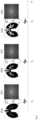
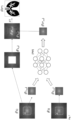
- Fig. 1 shows schematically and exemplarily the relationship between representations of an area of investigation in spatial space and in frequency space.
- a timeline is shown.
- metrological representations of an examination area are generated.
- the examination area is the lungs of a person.
- a first representation is generated.
- This can be a representation O1 of the examination area (lungs) in spatial space or a representation F 1 of the examination area (lungs) in frequency space.
- the representation O1 of the examination area in spatial space can be converted into a representation F1 of the examination area in frequency space using Fourier transformation ( FT ).
- the representation F1 of the examination area in frequency space can be converted into a representation O1 of the examination area in spatial space using inverse Fourier transformation (iFT ).
- the representations O1 and F1 can, for example, be representations of the examination area without a contrast agent or after application of an initial amount of contrast agent.
- the two representations O1 and F1 contain the same information about the area of investigation, only in a different representation.
- Another representation is generated.
- This can be a representation O2 of the examination area (lung) in spatial space or a representation F2 of the examination area (lung) in frequency space.
- the representation O2 of the examination area in spatial space can be converted into a representation F2 of the examination area in frequency space using Fourier transformation ( FT ).
- the representation F2 of the examination area in frequency space can be converted into a representation O2 of the examination area in spatial space using inverse Fourier transformation ( iFT ).
- the representations O2 and F2 can, for example, be representations of the examination area after application of a second amount of contrast agent.
- the two representations O2 and F2 contain the same information about the area under investigation, only in a different representation.
- Another representation is generated.
- This can be a representation O3 of the examination area (lung) in spatial space or a representation F3 of the examination area (lung) in frequency space.
- the representation O3 of the examination area in spatial space can be converted into a representation F3 of the examination area in frequency space using Fourier transformation ( FT ).
- the representation F3 of the examination area in frequency space can be converted into a representation O3 of the examination area in spatial space using inverse Fourier transformation ( iFT ).
- the representations O3 and F3 can, for example, be representations of the examination area after application of a third amount of contrast agent.
- the two representations O3 and F3 contain the same information about the study area, only in a different representation.
- the representations O1, O2, and O3 of the examination area in spatial space are the most common representations; humans can directly perceive such spatial representations.
- the representations O1, O2, and O3 demonstrate the influence that different amounts of contrast agent can have on the appearance of the examination area in an MR examination. In the present case, the amount of contrast agent increases from O1 via O2 to O3.
- the same information is also contained in the representations F1, F2, and F3; however, it is more difficult for humans to perceive it from the representations F1, F2, and F3.
- prediction model In order for the machine learning model (prediction model) according to the invention to be able to make the predictions described here, it must be configured (trained) accordingly in advance.
- prediction means that at least one representation of an examination region, which represents the examination region after an application of a specific amount of contrast agent in the frequency domain, is calculated on the basis of at least two representations of the examination region in the frequency domain, wherein the at least two representations represent the examination region after application of different amounts of contrast agent and/or after application of different contrast agents.
- At least a first representation of an examination area of an examination object and at least a second representation of the examination area of the examination object are used to predict at least a third representation of the examination area of the examination object.
- the at least one first, the at least one second and at least one third representation are representations of the area under investigation in the frequency space.
- the at least one first representation represents the examination area after application of a first amount of a first contrast agent, whereby this first amount can also be zero (no application of a contrast agent).
- the at least one second representation represents the examination region after application of a second amount of the first contrast agent or a second amount of a second contrast agent. If the first contrast agent is used to generate the second representation, the second amount is typically different from the first amount. If a second contrast agent is used, the second amount may be equal to or different from the first amount.
- the at least one third representation represents the examination region after application of a third amount of the first contrast agent or a third amount of the second contrast agent or a third amount of a third contrast agent. If the same contrast agent is used to generate the first representation, the second representation and the third representation, the third amount is usually not equal to the second amount and not equal to the first amount; for the first amount M1, the second amount M2 and the third amount M3, the following preferably applies: the first amount M1 is greater than or equal to zero, the second amount M2 is greater than the first amount M1 and the third amount M3 is greater than the second amount M2 (0 ⁇ M1 ⁇ M2 ⁇ M3).
- the amount of the other contrast agent may be equal to or different from the amount(s) of contrast agent(s) used to generate the first and/or second representation.
- the prediction model can therefore be trained to learn the influence of different amounts of contrast agent on representations of the examination area in the frequency domain, but it can also be trained to learn the influence of different contrast agents on representations of the examination area in the frequency domain.
- the prediction model is preferably created (configured, trained) using a self-learning algorithm in supervised machine learning.
- Training data is used for learning.
- This training data comprises, for each of a large number of examination objects, a plurality of representations of an examination area.
- the examination area is usually the same for all examination objects (e.g., a part of a human body or an organ or a part of an organ).
- the representations of the training data set are also referred to as reference representations in this description.
- the training data includes i) at least one first reference representation of the examination region in the frequency domain, representing the examination region without contrast agent or after application of a first amount of contrast agent, ii) at least one second reference representation of the examination region in the frequency domain, representing the examination region after application of a second amount of contrast agent, and iii) at least one third reference representation of the examination region in the frequency domain, representing the examination region after application of a third amount of contrast agent.
- the first, second, and third amounts of contrast agent and/or the respective contrast agents used differ from one another.
- the prediction model is trained to predict (calculate) for each object of investigation the at least one third reference representation based on the at least one first reference representation and the at least one second reference representation.
- the self-learning algorithm creates a statistical model based on the training data. This means that the algorithm doesn't simply memorize the examples; instead, it "recognizes" patterns and regularities in the training data. This allows the prediction model to evaluate even unknown data. Validation data can be used to test the accuracy of the evaluation of unknown data.
- the prediction model can be trained using supervised learning, meaning that the algorithm is presented with triples of data sets (first, second, and third representations) one after the other. The algorithm then learns a relationship between these data sets.
- the prediction model is or includes an artificial neural network.
- An artificial neural network comprises at least three layers of processing elements: a first layer with input neurons (nodes), an Nth layer with at least one output neuron (node), and N-2 inner layers, where N is a natural number and greater than 2.
- the input neurons are used to receive first and second representations.
- the output neurons are used to output at least one third representation for at least one first representation and at least one second representation.
- the processing elements of the layers between the input neurons and the output neurons are connected in a predetermined pattern with predetermined connection weights.
- the artificial neural network is preferably a so-called convolutional neural network (CNN for short).
- a convolutional neural network is capable of processing input data in the form of a matrix.
- a CNN essentially consists of filters (convolutional layer) and aggregation layers (pooling layer) that alternately repeat, and finally, one or more layers of "normal" fully connected neurons (dense/fully connected layer).
- the neural network can be trained, for example, using a backpropagation method.
- the goal is to achieve the most reliable mapping possible from given input data to given output data.
- the quality of the mapping is described by an error function ( loss function ).
- the goal is to minimize the error function.
- an artificial neural network is trained by changing the connection weights.
- connection weights between the processing elements contain information regarding the relationship between the at least one first representation and the at least one second representation on the one hand, and the at least one third representation on the other hand. This information can be used to predict at least one third representation based on at least one first and at least one second representation.
- a cross-validation method can be used to split the data into training and validation sets.
- the training set is used for backpropagation training of the network weights.
- the validation set is used to test the predictive accuracy of the trained network when applied to unknown data.
- the prediction model is a Generative Adversarial Network (GAN) (see e.g.: http://3dgan.csail.mit.edu/).
- GAN Generative Adversarial Network
- Examples of information about the subject being examined include: gender, age, weight, height, medical history, type, duration, and amount of medications already taken, blood pressure, central venous pressure, respiratory rate, serum albumin, total bilirubin, blood sugar, iron levels, respiratory capacity, and the like. This information about the subject being examined can also be retrieved from a database or an electronic patient record, for example.
- Examples of information on the area of investigation include: previous illnesses, operations, partial resection, liver transplantation, iron liver, fatty liver and the like.
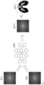
- Fig. 2 shows schematically and exemplarily how the Fig. 1
- the generated representations (F1), (F2), and (F3) of the examination area in frequency space can be used to train a prediction model (PM).
- the representations (F1), (F2), and (F3) form a set of training data for an examination object. Training is carried out using a large number of training data sets from a large number of examination objects.
- the representations (F1) and (F2) are a first and a second representation of an examination area in the frequency domain, whereby the representations represent the examination area after the application of different amounts of contrast agent (it is also possible that in one case no contrast agent has been applied).
- the representation (F3) is a third representation of the examination area in the frequency domain, which represents the examination area after the application of a third amount of contrast agent.
- the prediction model is Fig. 2 trained to predict the representation (F3) of the examination area in the frequency space from the representations (F1) and (F2) of the examination area in the frequency space.
- the representations (F1) and (F2) are input into the prediction model (PM), and the prediction model calculates a representation (F3*) from the representations (F1) and (F2).
- the asterisk (*) indicates that the representation (F3*) is a predicted representation.
- the calculated representation (F3*) is compared with the representation (F3).
- the deviations between the calculated representation (F3*) and the measured representation (F3) can be used in a backpropagation process to train the prediction model and reduce the deviations to a defined minimum. If the prediction model is based on a large number of training data sets from a large number of Once the objects of investigation have been trained and the prediction has reached a defined accuracy, the trained prediction model can be used for prediction.
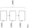
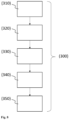
- Fig. 3 shows, by way of example and schematically in the form of a flow chart, a preferred embodiment of the method according to the invention for training a machine learning model.
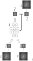
- the use of the trained prediction model for prediction is exemplary and schematically shown in Fig. 4 shown.
- Fig. 4 shows that in Fig. 2 trained prediction model (PM).
- the prediction model is used to predict at least a third representation of the examination area of the examination object in the frequency domain based on at least a first representation of the examination area of the examination object in the frequency domain and at least a second representation of the examination area of the examination object in the frequency domain, wherein the representations represent the examination area after the application of different amounts of contrast agent.
- a first representation (F ⁇ 1) and a second representation (F ⁇ 2) of the examination area in the frequency domain are input into the prediction model, and the prediction model generates (calculates) a third representation (F ⁇ 3*).
- the tilde ( ⁇ ) signals that the representations are representations of a new examination object, for which no representations are usually available that were used in the training procedure for training the prediction model.
- the asterisk (*) signals that the representation (F ⁇ 3*) is a predicted representation.
- the representation (F ⁇ 3*) of the examination area in the frequency domain can be transformed, for example, using inverse Fourier transformation (iFT) into a representation ( ⁇ 3*) of the examination area in the spatial domain.
- iFT inverse Fourier transformation
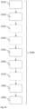
- Fig. 5 shows, by way of example and schematically in the form of a flow chart, a preferred embodiment of the method according to the invention for predicting a representation of an examination region of an examination object.
- the representations of the study area used for training, validation and prediction are representations of the study area in frequency space (also called spatial frequency space or Fourier space or frequency domain or Fourier representation).
- the raw data is usually generated as so-called k-space data due to the measurement procedure described above.
- This k-space data is a representation of an examination region in a frequency domain; i.e., such k-space data can be used for training, validation, and prediction. If representations are present in the spatial domain, such representations in the spatial domain can be converted (transformed), for example, using Fourier transformation, into a representation in the frequency domain; conversely, representations in the frequency domain can be converted (transformed), for example, using inverse Fourier transformation, into a representation in the spatial domain.
- this representation of the examination area can be converted into a two-dimensional representation of the examination area in frequency space by means of a 2D Fourier transformation.
- a three-dimensional image (volume representation) of an examination area can be treated as a stack of two-dimensional images. It is also conceivable that the three-dimensional image is converted into a three-dimensional representation of the examination area in the frequency domain using a 3D Fourier transform.
- Co-registration also called “image registration” in the prior art
- image registration is an important process in digital image processing and serves to align two or more images of the same scene, or at least similar scenes, as closely as possible.
- One of the images is designated as the reference image, and the others are called object images.
- object images To optimally adapt these to the reference image, a compensating transformation is calculated.
- the images to be registered differ from one another because they were acquired from different positions, at different times, and/or with different sensors.
- the individual representations were generated at different times; on the other hand, they differ with regard to the contrast agent content in the examination area and/or with regard to the contrast agent used.
- representations of the examination area in frequency space has the advantage over the use of representations of the examination area in spatial space that the training, validation, and prediction methods are more tolerant of errors in image registration. In other words, if representations in frequency space are not precisely superimposed, this has a smaller impact than if representations in spatial space are not precisely superimposed.
- frequency-space representation Another advantage of using frequency-space representation is that it allows contrast information, which is important for training and prediction, to be separated from detailed information (fine structure). This makes it possible to focus on the information the predictive model should learn during training, and also focus on the information the predictive model should predict during prediction: contrast information.
- contrast information in a spatial-space representation of an examination area is typically distributed throughout the entire representation (each pixel/voxel carries contrast information)
- the contrast information in a frequency-space representation of an examination area is encoded in and around the center of the frequency space.
- the low frequencies in a frequency-space representation are responsible for contrast
- the high frequencies contain information about fine structures.
- a region can be specified in the representations of the study area used for training, validation and prediction.
- the area can be specified, for example, by a user of the computer system according to the invention entering one or more parameters into the computer system according to the invention and/or selecting them from a list which determine the shape and/or size of the area
- the specification takes place automatically, for example, by the computer system according to the invention, which has been configured accordingly to select a predefined area in the representations of the examination area.
- the specified range is usually smaller than the frequency space filled by the respective representation, but in any case includes the center of the frequency space.
- a region of the representation encompassing the center of the frequency space (also called the origin or zero point) contains the contrast information relevant for the method according to the invention. If the specified region is smaller than the frequency space filled by the respective representation, the computational effort required for training, validation, and subsequent prediction is reduced. Thus, the size of the region can directly influence the computational effort.
- the user of the computer system can decide for themselves whether they want training, validation, and prediction based on the complete representations of the examination region in the frequency space (which means maximum computational effort) or whether they want to reduce the computational effort by specifying a region that is smaller than the frequency space filled by the representations.
- the size of the specified region can directly influence the required computational effort.
- the specified region typically has the same dimension as the frequency space: in the case of a 2D representation in a 2D frequency space, the specified region is typically a surface; in the case of a 3D representation in a 3D frequency space, the specified region is typically a volume.
- the specified area can, in principle, have any shape; for example, it can be round and/or square, concave and/or convex.
- the area is cuboid or cube-shaped in the case of a 3D frequency space in a Cartesian coordinate system and rectangular or square in the case of a 2D frequency space in a Cartesian coordinate system.
- the specified area is spherical or circular, or has another shape.
- the geometric center of gravity of the specified area coincides with the center of the frequency space.
- the representations used for training, validation, and prediction are reduced to the specified range.
- the term "reducing" means that all parts of a representation that do not lie within the specified range are cut away (discarded) or covered by a mask.
- Masking involves covering the areas that lie outside the specified range with a mask, leaving only the specified area uncovered. For example, covering with a mask can set the color values of the corresponding pixels/voxels to zero (black).
- the reduced representations can be used for training, validation and prediction.
- a third representation of an area of investigation is to be predicted for an object of investigation based on a first and a second representation
- the reduced first representation and the reduced second representation can be fed into the prediction model, and the prediction model then generates a reduced third representation.
- the detailed information that was cut out or covered during the reduction can be fed back into the predicted representation.
- the parts of the first representation that lie outside the specified area can be added to the reduced third representation.
- the parts of the second representation that lie outside the specified area are added to the reduced third representation.
- both parts of the first representation that lie outside the specified area and parts of the second representation that lie outside the specified area are fed into the reduced third representation.
- the third representation is supplemented by parts of the first and/or second representation that were cut away or masked during the reduction process.
- the result is a supplemented third representation.
- a position-space representation can then be obtained from the supplemented third representation using a transformation (e.g., an inverse Fourier transform).
- the resulting signal strengths for different location coordinates can be converted into gray values or color values in a further step in order to have a digital image in a common image format (e.g. DICOM).
- DICOM common image format
- the representation of the study area in the spatial representation can be displayed on a screen, printed out and/or stored in a data storage device.
- Fig. 6 shows, by way of example and schematically, a step in training a prediction model according to a preferred embodiment of the present invention.
- a first representation (F1), a second representation (F2) and a third representation (F3) of an examination area of an examination object in the frequency space are received.
- an area A of the same size and shape is specified.
- the area A in each case comprises the center of the frequency space and in this case has a square shape, whereby the geometric center of gravity of the square coincides with the center of the frequency space.
- the representations (F1), (F2) and (F3) are reduced to the respectively specified area A : this results in three reduced representations (F1 red ), (F2 red ) and (F3 red ).
- the reduced representations are used for training.
- the prediction model is trained to predict the reduced representation (F3 red ) from the reduced representations (F1 red ) and (F2 red ) .
- the reduced representations (F1 red ) and (F2 red ) are fed to the prediction model (PM) and the prediction model calculates a reduced representation (F3* red ) that should be as close as possible to the reduced representation (F3 red ).
- Fig. 7 shows an example and schematically how the Fig. 6 trained prediction model can be used for prediction.
- a first representation (F ⁇ 1) and a second representation (F ⁇ 2) of the examination area are received in the frequency domain and each reduced to a specified area A.
- the reduced first representation (F ⁇ 1 red ) and the reduced second representation (F ⁇ 2 red ) are fed to the trained prediction model (PM).
- the trained prediction model (PM) calculates from the reduced representations (F ⁇ 1 red ) and (F ⁇ 2 red ) a reduced third representation (F ⁇ 3 red *).
- the reduced third representation (F ⁇ 3 red *) is supplemented by that area of the received first representation (F ⁇ 1) that was discarded when reducing the received first representation (F ⁇ 1).
- those parts of the received first representation (F ⁇ 1) that lie outside (not within) the specified area are supplemented to form the reduced third representation (F ⁇ 3 red *).
- parts of the received second representation (F ⁇ 2) can also be supplemented to form the reduced third representation (F ⁇ 3 red *) instead of or in addition to parts of the received first representation (F ⁇ 1).
- Fig. 8 shows schematically in the form of a flowchart a preferred embodiment of the inventive method for training a machine learning model.
- Fig. 9 shows schematically in the form of a flow chart a preferred embodiment of the method according to the invention for predicting a representation of an examination region of an examination object.
- Fig. 10 shows schematically in the form of a flow chart a further preferred embodiment of the method according to the invention for predicting a representation of an examination region of an examination object.
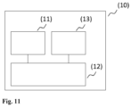
- FIG 11 shows schematically and by way of example an embodiment of the computer system according to the invention.
- the computer system (10) comprises a receiving unit (11), a control and computing unit (12), and an output unit (13).
- a “computer system” is an electronic data processing system that processes data using programmable computing instructions. Such a system typically includes a control and processing unit, often referred to as a "computer,” which includes a processor for performing logical operations and a RAM for loading a computer program, as well as peripherals.
- a control and processing unit often referred to as a "computer”
- processor for performing logical operations
- RAM for loading a computer program
- peripherals refers to all devices connected to a computer that serve to control the computer and/or act as input and output devices. Examples include monitors (screens), printers, scanners, mice, keyboards, joysticks, drives, cameras, microphones, speakers, etc. Internal connectors and expansion cards are also considered peripherals in computer technology.
- Today's computer systems are often divided into desktop PCs, portable PCs, laptops, notebooks, netbooks and tablet PCs and so-called handhelds (e.g., smartphones); all of these systems can be used to implement the invention.
- Inputs to the computer system are made via input devices such as a keyboard, a mouse, a microphone, a touch-sensitive display, and/or the like.
- Outputs are made via the output unit (13), which can in particular be a monitor (screen), a printer, and/or a data storage device.
- the computer system (10) is configured to predict, from at least two representations of an examination region in the frequency domain, which represent the examination region after application of different amounts of contrast agent, a representation of the examination region that shows the examination region after application of a specific amount of contrast agent, without this specific amount actually having to be administered.
- the control and computing unit (12) serves to control the receiving unit (11) and the output unit (13), to coordinate the data and signal flows between the various units, to process representations of the examination area, and to generate artificial radiological images. It is conceivable that several control and computing units are present.
- the receiving unit (11) serves to receive representations of an examination area.
- the representations can, for example, be transmitted from a magnetic resonance tomograph or a computed tomograph or read from a data memory.
- the magnetic resonance tomograph or the computed tomograph can be a component of the computer system according to the invention.
- the computer system according to the invention is a component of a magnetic resonance tomograph or a computed tomograph.
- the transmission of representations can take place via a network connection or a direct connection.
- the transmission of representations can take place via a radio connection (WLAN, Bluetooth, mobile radio and/or the like) and/or via a cable. It is conceivable that several receiving units are present.
- the data memory can also be a component of the
- the data storage device can be part of the computer system according to the invention or connected to it, for example, via a network. It is conceivable that multiple data storage devices are present.
- the receiving unit receives the representations and, if applicable, other data (such as information on the object under examination, recording parameters and/or the like) and transmits them to the control and computing unit.
- other data such as information on the object under examination, recording parameters and/or the like
- the control and computing unit is configured to generate artificial radiological images based on the received data.
- the output unit (13) can be used to display the artificial radiological images (e.g., on a monitor), output them (e.g., via a printer), and/or store them in a data storage device. Multiple output units are conceivable.
- the invention can be used to reduce the amount of contrast agent in a radiological examination.
- the prediction model can be trained to predict a third representation of the examination region of the examination object based on a first representation of an examination region of an examination object, which represents the examination region without contrast agent or after application of a first amount of contrast agent, and based on a second representation of the examination region of the examination object, which represents the examination region after application of a second amount of contrast agent.
- the third representation represents the examination region after application of a third amount of contrast agent, the third amount being greater than the first amount and the second amount. Therefore, only a first amount (which can also be zero) and a second amount of contrast agent need be applied to generate radiological images that appear as if a larger third amount of contrast agent had been applied.
- the invention can be used to generate artificial radiological images that show an examination area of an examination subject after application of a contrast agent, even though a different contrast agent has been applied.
- the invention can be used to generate an artificial radiological image based on a radiological image of a radiological examination (e.g., a magnetic resonance imaging scan) that shows the result of another radiological examination (e.g., the result of a computed tomography scan).
- a radiological examination e.g., a magnetic resonance imaging scan
- another radiological examination e.g., the result of a computed tomography scan
Landscapes
- Health & Medical Sciences (AREA)
- Life Sciences & Earth Sciences (AREA)
- Engineering & Computer Science (AREA)
- Physics & Mathematics (AREA)
- Medical Informatics (AREA)
- Theoretical Computer Science (AREA)
- Radiology & Medical Imaging (AREA)
- General Health & Medical Sciences (AREA)
- Biophysics (AREA)
- Nuclear Medicine, Radiotherapy & Molecular Imaging (AREA)
- Veterinary Medicine (AREA)
- Pathology (AREA)
- Public Health (AREA)
- Biomedical Technology (AREA)
- Heart & Thoracic Surgery (AREA)
- Molecular Biology (AREA)
- Surgery (AREA)
- Animal Behavior & Ethology (AREA)
- General Physics & Mathematics (AREA)
- Optics & Photonics (AREA)
- High Energy & Nuclear Physics (AREA)
- Pulmonology (AREA)
- Hematology (AREA)
- Apparatus For Radiation Diagnosis (AREA)
- Magnetic Resonance Imaging Apparatus (AREA)
- Medicines Containing Antibodies Or Antigens For Use As Internal Diagnostic Agents (AREA)
- Pharmaceuticals Containing Other Organic And Inorganic Compounds (AREA)
Claims (14)
- Procédé mis en œuvre par ordinateur, comprenant les étapes suivantes consistant à :- recevoir une première représentation (F̃1) d'une zone d'examen d'un objet d'examen, la première représentation (F̃1) représentant la zone d'examen sans agent de contraste ou après application d'une première quantité d'agent de contraste,- recevoir une deuxième représentation (F̃2) de la zone d'examen de l'objet d'examen, la deuxième représentation (F̃2) représentant la zone d'examen après une application d'une deuxième quantité d'agent de contraste,- amener au moins une partie de la première représentation (F̃1) et au moins une partie de la deuxième représentation (F̃2) à un modèle (PM) d'apprentissage automatique,- recevoir, à partir du modèle (PM) d'apprentissage automatique, une troisième représentation (F̃3*) de la zone d'examen, la troisième représentation (F̃3*) représentant la zone d'examen après application d'une troisième quantité d'agent de contraste,- sortir et/ou enregistrer une représentation (Õ3*) de la zone d'examen dans une visualisation du domaine spatial,caractérisé en ce que la première représentation (F̃1), la deuxième représentation (F̃2) et la troisième représentation (F̃3*) représentent la zone d'examen de l'objet d'examen dans le domaine fréquentiel,le procédé comprenant en outre les étapes suivantes consistant à :- produire la représentation (Õ3*) de la zone d'examen dans la visualisation du domaine spatial sur la base de la troisième représentation (F̃3*).
- Procédé mis en œuvre par ordinateur selon la revendication 1,
dans lequel l'étape consistant à amener au moins une partie de la première représentation (F̃1) et au moins une partie de la deuxième représentation (F̃2) à un modèle d'apprentissage automatique (PM) comprend les étapes suivantes consistant à :- spécifier une zone (A) dans la première représentation reçue (F̃1) et dans la deuxième représentation reçue (F̃2), la zone spécifiée (A) comprenant le centre du domaine fréquentiel,- réduire la première représentation (F̃1) et la deuxième représentation (F̃2) à la zone spécifiée (A), une première représentation réduite (F̃1red) et une deuxième représentation réduite (F̃2red) étant ainsi obtenues,- amener la première représentation réduite (F̃1red) et la deuxième représentation réduite (F2red) au modèle (PM) d'apprentissage automatique. - Procédé mis en œuvre par ordinateur selon la revendication 2,
dans lequel l'étape consistant à produire une représentation (Õ3*) de la zone d'examen dans une visualisation du domaine spatial sur la base de la troisième représentation (F̃3*) comprend les étapes suivantes consistant à :- compléter la troisième représentation (F̃3*red) par les parties (F̃1DI) de la première représentation reçue (F̃1) et/ou de la deuxième représentation reçue (F̃2) qui ne se trouvent pas dans la zone spécifiée (A),- transformer la troisième représentation complétée obtenue après avoir complété la troisième représentation (F̃3*red) en la représentation (Õ3*) de la zone d'examen dans la visualisation du domaine spatial. - Procédé mis en œuvre par ordinateur selon l'une quelconque des revendications 1 à 3, dans lequel la première représentation (F̃1) représente la zone d'examen sans agent de contraste ou après application de la première quantité d'un agent de contraste, dans lequel la deuxième représentation (F̃2) représente la zone d'examen après application d'une deuxième quantité de l'agent de contraste, la deuxième quantité étant différente de la première quantité, dans lequel la troisième représentation (F̃3*) représente la zone d'examen après application d'une troisième quantité de l'agent de contraste, la troisième quantité étant différente de la première quantité et/ou différente de la deuxième quantité.
- Procédé mis en œuvre par ordinateur selon l'une quelconque des revendications 1 à 4, dans lequel la première quantité d'agent de contraste est supérieure ou égale à zéro, dans lequel la deuxième quantité d'agent de contraste est supérieure à la première quantité d'agent de contraste et dans lequel la troisième quantité d'agent de contraste est supérieure à la deuxième quantité d'agent de contraste.
- Procédé mis en œuvre par ordinateur selon l'une quelconque des revendications 1 à 5, dans lequel la première représentation (F̃1) représente la zone d'examen sans agent de contraste ou après application d'une première quantité d'un premier agent de contraste, dans lequel la deuxième représentation (F̃2) représente la zone d'examen après application d'une deuxième quantité d'un deuxième agent de contraste, dans lequel la troisième représentation (F̃3*) représente la zone d'examen après application d'une troisième quantité d'un troisième agent de contraste, le troisième agent de contraste étant différent du premier agent de contraste et/ou différent du deuxième agent de contraste ou le deuxième agent de contraste étant différent du premier agent de contraste.
- Procédé mis en œuvre par ordinateur selon l'une quelconque des revendications 1 à 6, dans lequel la première représentation (F̃1) et la deuxième représentation (F̃2) sont le résultat d'un examen radiologique.
- Procédé mis en œuvre par ordinateur selon la revendication 7, dans lequel l'examen radiologique est un examen d'imagerie par résonance magnétique, un examen par tomographie informatisée ou un examen par ultrasons.
- Procédé mis en œuvre par ordinateur selon l'une quelconque des revendications 1 à 8, dans lequel la première représentation (F̃1) et la deuxième représentation (F̃2) sont des données d'espace k d'un examen d'imagerie par résonance magnétique.
- Procédé mis en œuvre par ordinateur selon l'une quelconque des revendications 1 à 9, dans lequel la première représentation (F̃1) et la deuxième représentation (F̃2) sont des visualisations du domaine spatial transformées de Fourier.
- Procédé mis en œuvre par ordinateur selon l'une quelconque des revendications 1 à 7, comprenant en outre les étapes suivantes consistant à :- recevoir une première représentation du domaine spatial (O1) de la zone d'examen de l'objet d'examen, la première représentation du domaine spatial (O1) représentant la zone d'examen sans agent de contraste ou après application d'une première quantité d'agent de contraste,- recevoir une deuxième représentation du domaine spatial (O2) de la zone d'examen de l'objet d'examen, la deuxième représentation du domaine spatial (O2) représentant la zone d'examen après application d'une deuxième quantité d'agent de contraste,- produire la première représentation (F̃1) de la zone d'examen de l'objet d'examen dans le domaine fréquentiel à partir de la première représentation du domaine spatial (O1), de préférence au moyen d'une transformation de Fourier (FT).- produire la deuxième représentation (F̃2) de la zone d'examen de l'objet d'examen dans le domaine fréquentiel à partir de la deuxième représentation du domaine spatial (O2), de préférence au moyen d'une transformation de Fourier (FT).
- Procédé mis en œuvre par ordinateur selon l'une quelconque des revendications 1 à 11, comprenant en outre l'étape suivante consistant à : former le modèle d'apprentissage automatique, la formation comprenant les sous-étapes suivantes consistant à :- recevoir un ensemble de données d'apprentissage, l'ensemble de données d'apprentissage comprenant, pour une pluralité d'objets d'examen, respectivement i) une première représentation de référence (F1) d'une zone d'examen de l'objet d'examen dans le domaine fréquentiel, ii) une deuxième représentation de référence (F2) de la zone d'examen de l'objet d'examen dans le domaine fréquentiel et iii) une troisième représentation de référence (F3) de la zone d'examen de l'objet d'examen dans le domaine fréquentiel, la première représentation de référence (F1) représentant la zone d'examen après application d'une première quantité d'un agent de contraste, la première quantité pouvant également être nulle, la deuxième représentation de référence (F2) représentant la zone d'examen après application d'une deuxième quantité de l'agent de contraste, la troisième représentation de référence (F3) représentant la zone d'examen après application d'une troisième quantité de l'agent de contraste,- spécifier une zone (A) dans les représentations de référence, la zone spécifiée (A) comprenant le centre du domaine fréquentiel,- réduire les représentations (F1, F2, F3) à la zone spécifiée (A), une première représentation de référence réduite (F1red), une deuxième représentation de référence réduite (F2red) et une troisième représentation de référence réduite (F3red) étant obtenues pour chaque objet d'examen,- pour chaque objet d'examen : amener la première représentation de référence réduite (F1red) et la deuxième représentation de référence réduite (F2red) au modèle (PM) d'apprentissage automatique, le modèle (PM) d'apprentissage automatique étant formé pour générer une représentation réduite (F3*red) de la région d'examen dans le domaine fréquentiel après application de la troisième quantité d'agent de contraste sur la base de la première représentation de référence réduite (F1red) et de la deuxième représentation de référence réduite (F2red), l'apprentissage comprenant la minimisation d'une fonction d'erreur, la fonction d'erreur quantifiant des écarts entre la représentation réduite générée (F3*red) de la zone d'examen et la troisième représentation de référence réduite (F3red).
- Système informatique (10) comprenant• une unité de réception (11),• une unité de commande et de calcul (12), et• une unité de sortie (13),- dans lequel l'unité de commande et de calcul (12) est configurée pour amener l'unité de réception (11) à recevoir au moins deux représentations d'une zone d'examen d'un objet d'examen, une première représentation (F̃1) et une deuxième représentation (F̃2), la première représentation (F̃1) représentant la zone d'examen sans agent de contraste ou après application d'une première quantité d'agent de contraste, la deuxième représentation (F̃2) représentant la zone d'examen après application d'une deuxième quantité d'agent de contraste,- dans lequel l'unité de commande et de calcul (12) est configurée pour amener au moins une partie de la première représentation (F̃1) et au moins une partie de la deuxième représentation (F̃2) à un modèle (PM) d'apprentissage automatique,- dans lequel l'unité de commande et de calcul (12) est configurée pour recevoir du modèle (PM) d'apprentissage automatique une troisième représentation (F̃3*) de la zone d'examen, la troisième représentation (F̃3*) représentant la zone d'examen après application d'une troisième quantité d'agent de contraste,- dans lequel l'unité de commande et de calcul (12) est configurée pour produire sur la base de la troisième représentation (F̃3*) une représentation (Õ3*) de la zone d'examen dans le domaine spatial,- dans lequel l'unité de commande et de calcul (12) est configurée pour amener l'unité de sortie (13) à sortir et/ou à enregistrer une représentation (Õ3*) de la zone d'examen dans le domaine spatialcaractérisé en ce que la première représentation (F̃1), la deuxième représentation (F̃2) et la troisième représentation (F̃3*) représentent la zone d'examen de l'objet d'examen dans le domaine fréquentiel,dans lequel l'unité de commande et de calcul (12) est en outre configurée pour produire, sur la base de la troisième représentation (F̃3*), la représentation (Õ3*) de la zone d'examen dans le domaine spatial.
- Programme informatique, qui peut être chargé dans une mémoire de travail d'un système informatique (10) et qui y amène le système informatique (10) à exécuter les étapes suivantes consistant à :- recevoir une première représentation (F̃1) d'une zone d'examen d'un objet d'examen, la première représentation (F̃1) représentant la zone d'examen sans agent de contraste ou après application d'une première quantité d'agent de contraste,- recevoir une deuxième représentation (F̃2) de la zone d'examen de l'objet d'examen, la deuxième représentation (F̃2) représentant la zone d'examen après une application d'une deuxième quantité d'agent de contraste,- amener au moins une partie de la première représentation (F̃1) et au moins une partie de la deuxième représentation (F̃2) à un modèle (PM) d'apprentissage automatique,- recevoir, à partir du modèle (PM) d'apprentissage automatique, une troisième représentation (F̃3*) de la zone d'examen, la troisième représentation (F̃3*) représentant la zone d'examen après application d'une troisième quantité d'agent de contraste,- sortir et/ou enregistrer une représentation (Õ3*) de la zone d'examen dans une visualisation du domaine spatial,caractérisé en ce que la première représentation (F̃1), la deuxième représentation (F̃2) et la troisième représentation (F̃3*) représentent la zone d'examen de l'objet d'examen dans le domaine fréquentiel,dans lequel le programme informatique amène en outre le système informatique (10) à exécuter l'étape suivante consistant à :- produire la représentation (Õ3*) de la zone d'examen dans la visualisation du domaine spatial sur la base de la troisième représentation (F̃3*).
Applications Claiming Priority (3)
| Application Number | Priority Date | Filing Date | Title |
|---|---|---|---|
| EP21160325 | 2021-03-02 | ||
| EP21167116 | 2021-04-07 | ||
| PCT/EP2021/083321 WO2022184297A1 (fr) | 2021-03-02 | 2021-11-29 | Apprentissage automatique dans le domaine de la radiologie avec injecton d'agent de contraste |
Publications (2)
| Publication Number | Publication Date |
|---|---|
| EP4143779A1 EP4143779A1 (fr) | 2023-03-08 |
| EP4143779B1 true EP4143779B1 (fr) | 2025-06-04 |
Family
ID=78825058
Family Applications (2)
| Application Number | Title | Priority Date | Filing Date |
|---|---|---|---|
| EP21820574.8A Active EP4143779B1 (fr) | 2021-03-02 | 2021-11-29 | Apprentissage automatique dans le domaine de la radiologie assistée par contraste |
| EP21820576.3A Active EP4302259B1 (fr) | 2021-03-02 | 2021-11-29 | Apprentissage automatique dans le domaine de la radiologie assistée par contraste |
Family Applications After (1)
| Application Number | Title | Priority Date | Filing Date |
|---|---|---|---|
| EP21820576.3A Active EP4302259B1 (fr) | 2021-03-02 | 2021-11-29 | Apprentissage automatique dans le domaine de la radiologie assistée par contraste |
Country Status (6)
| Country | Link |
|---|---|
| US (2) | US12611152B2 (fr) |
| EP (2) | EP4143779B1 (fr) |
| JP (2) | JP2024509817A (fr) |
| AU (2) | AU2021430556A1 (fr) |
| CA (3) | CA3219146A1 (fr) |
| WO (2) | WO2022184297A1 (fr) |
Families Citing this family (17)
| Publication number | Priority date | Publication date | Assignee | Title |
|---|---|---|---|---|
| CN115398555A (zh) * | 2020-04-03 | 2022-11-25 | 拜耳公司 | 生成放射线图像 |
| CA3219146A1 (fr) | 2021-03-02 | 2022-09-09 | Bayer Aktiengesellschaft | Apprentissage automatique dans le domaine de la radiologie avec injecton d'agent de contraste |
| EP4343786A1 (fr) * | 2022-09-20 | 2024-03-27 | Siemens Healthineers AG | Construction d'un modèle d'apprentissage automatique pour prédire des informations de contexte sémantique pour des mesures d'imagerie médicale à contraste amélioré |
| EP4471710B1 (fr) | 2023-05-30 | 2025-12-17 | Bayer Aktiengesellschaft | Détection d'artéfacts dans des enregistrements médicaux synthétiques |
| EP4475137B1 (fr) | 2023-06-05 | 2025-12-03 | Bayer Aktiengesellschaft | Génération d'enregistrements radiologiques artificiels à contraste amélioré |
| EP4475070B1 (fr) | 2023-06-05 | 2026-04-22 | Bayer Aktiengesellschaft | Détection d'artéfacts dans des enregistrements médicaux synthétiques |
| WO2024251601A1 (fr) | 2023-06-05 | 2024-12-12 | Bayer Aktiengesellschaft | Génération d'images radiologiques artificielles à contraste amélioré |
| EP4492324A1 (fr) | 2023-07-12 | 2025-01-15 | Bayer AG | Détection d'artéfacts dans des enregistrements médicaux synthétiques |
| EP4498324A1 (fr) | 2023-07-25 | 2025-01-29 | Bayer AG | Détection d'artéfacts dans des images synthétiques |
| EP4560648A1 (fr) | 2023-11-22 | 2025-05-28 | Bayer AG | Génération de données d'apprentissage synthétiques |
| EP4567715A1 (fr) | 2023-12-06 | 2025-06-11 | Bayer Aktiengesellschaft | Génération de représentations synthétiques |
| EP4567716A1 (fr) | 2023-12-06 | 2025-06-11 | Bayer Aktiengesellschaft | Génération de représentations synthétiques |
| WO2025119803A1 (fr) | 2023-12-06 | 2025-06-12 | Bayer Aktiengesellschaft | Génération de représentations médicales de synthèse |
| EP4571650A1 (fr) | 2023-12-12 | 2025-06-18 | Bayer AG | Génération d'images synthétiques |
| EP4575997A1 (fr) | 2023-12-18 | 2025-06-25 | Bayer Aktiengesellschaft | Génération d'images synthétiques |
| WO2025190826A1 (fr) | 2024-03-15 | 2025-09-18 | Bayer Aktiengesellschaft | Génération d'une image médicale synthétique |
| EP4672132A1 (fr) | 2024-06-26 | 2025-12-31 | Bayer Aktiengesellschaft | Génération d'images radiologiques synthétiques |
Family Cites Families (11)
| Publication number | Priority date | Publication date | Assignee | Title |
|---|---|---|---|---|
| JP2007275481A (ja) * | 2006-04-12 | 2007-10-25 | Hitachi Medical Corp | 磁気共鳴イメージング装置 |
| US9594143B2 (en) * | 2011-09-08 | 2017-03-14 | Mayo Foundation For Medical Education And Research | System and method for controlling calibration and delay phases of parallel, contrast-enhanced magnetic resonance imaging |
| EP2800979A4 (fr) * | 2012-01-06 | 2015-06-24 | Childrens Hosp Medical Center | Imagerie par corrélation pour imagerie par résonance magnétique multi-balayage avec acquisition de données multi-canaux |
| US10096109B1 (en) | 2017-03-31 | 2018-10-09 | The Board Of Trustees Of The Leland Stanford Junior University | Quality of medical images using multi-contrast and deep learning |
| WO2018200493A1 (fr) | 2017-04-25 | 2018-11-01 | The Board Of Trustees Of The Leland Stanford Junior University | Réduction de dose pour imagerie médicale à l'aide de réseaux neuronaux à convolution profonde |
| BR112020007105A2 (pt) | 2017-10-09 | 2020-09-24 | The Board Of Trustees Of The Leland Stanford Junior University | método para treinar um dispositivo de diagnóstico por imagem para realizar uma imagem para diagnóstico médico com uma dose reduzida de agente de contraste |
| CN116741352A (zh) * | 2017-11-24 | 2023-09-12 | 佳能医疗系统株式会社 | 医用数据处理装置、磁共振成像装置及学习完毕模型生成方法 |
| KR102708986B1 (ko) | 2018-04-19 | 2024-09-24 | 서틀 메디컬, 인크. | 딥 러닝을 사용하여 자기 공명 이미징을 향상시키기 위한 시스템들 및 방법들 |
| EP3807814A4 (fr) | 2018-06-15 | 2022-03-16 | Subtle Medical, Inc. | Systèmes et méthodes de normalisation d'imagerie par résonance magnétique à l'aide d'un apprentissage profond |
| CA3219146A1 (fr) | 2021-03-02 | 2022-09-09 | Bayer Aktiengesellschaft | Apprentissage automatique dans le domaine de la radiologie avec injecton d'agent de contraste |
| JP2024512369A (ja) | 2021-03-09 | 2024-03-19 | バイエル・アクチエンゲゼルシヤフト | 造影放射線学の分野における機械学習 |
-
2021
- 2021-11-29 CA CA3219146A patent/CA3219146A1/fr active Pending
- 2021-11-29 WO PCT/EP2021/083321 patent/WO2022184297A1/fr not_active Ceased
- 2021-11-29 AU AU2021430556A patent/AU2021430556A1/en active Pending
- 2021-11-29 US US18/280,192 patent/US12611152B2/en active Active
- 2021-11-29 EP EP21820574.8A patent/EP4143779B1/fr active Active
- 2021-11-29 JP JP2023553036A patent/JP2024509817A/ja active Pending
- 2021-11-29 JP JP2023553034A patent/JP7608630B2/ja active Active
- 2021-11-29 CA CA3212207A patent/CA3212207A1/fr not_active Withdrawn
- 2021-11-29 US US18/280,193 patent/US12611153B2/en active Active
- 2021-11-29 AU AU2021431204A patent/AU2021431204A1/en active Pending
- 2021-11-29 CA CA3218956A patent/CA3218956A1/fr active Pending
- 2021-11-29 WO PCT/EP2021/083324 patent/WO2022184298A1/fr not_active Ceased
- 2021-11-29 EP EP21820576.3A patent/EP4302259B1/fr active Active
Also Published As
| Publication number | Publication date |
|---|---|
| US12611153B2 (en) | 2026-04-28 |
| JP2024509817A (ja) | 2024-03-05 |
| EP4302259B1 (fr) | 2024-12-18 |
| EP4302259A1 (fr) | 2024-01-10 |
| US20240050054A1 (en) | 2024-02-15 |
| AU2021430556A1 (en) | 2023-08-31 |
| EP4143779A1 (fr) | 2023-03-08 |
| WO2022184298A1 (fr) | 2022-09-09 |
| WO2022184297A1 (fr) | 2022-09-09 |
| JP2024508019A (ja) | 2024-02-21 |
| CA3218956A1 (fr) | 2022-09-09 |
| JP7608630B2 (ja) | 2025-01-06 |
| AU2021431204A1 (en) | 2023-08-31 |
| CA3219146A1 (fr) | 2022-09-09 |
| US12611152B2 (en) | 2026-04-28 |
| CA3212207A1 (fr) | 2022-09-09 |
| US20240050053A1 (en) | 2024-02-15 |
Similar Documents
| Publication | Publication Date | Title |
|---|---|---|
| EP4143779B1 (fr) | Apprentissage automatique dans le domaine de la radiologie assistée par contraste | |
| EP4041075B1 (fr) | Génération d'enregistrements irm du foie sans rehaussement du contraste | |
| EP4031893B1 (fr) | Génération d'enregistrements irm du foie | |
| WO2021197996A1 (fr) | Génération d'images radiologiques | |
| DE102009044075A1 (de) | Auf aktiven elektronischen Patientenakten basierendes Unterstützungssystem unter Nutzung von lernenden Automaten | |
| WO2021069343A1 (fr) | Accélération d'examens irm | |
| WO2024052156A1 (fr) | Génération d'images radiologiques améliorées par contraste artificiel | |
| EP3804615A1 (fr) | Génération d'enregistrements irm du foie | |
| EP4482393B1 (fr) | Prédiction d'une représentation d'une zone d'examen d'un objet d'examen après l'application de différentes quantités d'un agent de contraste | |
| EP4483197B1 (fr) | Prédiction d'une représentation d'une zone d'examen d'un objet d'examen dans un état d'une séquence d'états | |
| DE102014210218B4 (de) | Verfahren zum Generieren von medizinischen Bilddatensätzen, sowie medizinisches Bildgebungsgerät | |
| EP4143784B1 (fr) | Apprentissage automatique dans le domaine de la radiologie assistée par contraste | |
| EP4154797A1 (fr) | Procédé de détermination d'un plan de coupe pertinent pour le diagnostic | |
| EP4332601B1 (fr) | Génération d'enregistrements radiologiques artificiels renforcés par un agent de contraste | |
| EP4581640A1 (fr) | Génération d'images radiologiques de synthese | |
| EP4332983B1 (fr) | Production d'enregistrements radiologiques synthétiques | |
| EP4485474B1 (fr) | Génération d'enregistrements radiologiques artificiels à contraste amélioré | |
| EP4475137B1 (fr) | Génération d'enregistrements radiologiques artificiels à contraste amélioré | |
| DE102023212265B4 (de) | Unterstützungsvorrichtung zum Abgeben einer Handlungsempfehlung an einen Operateur | |
| WO2024100234A1 (fr) | Génération d'images radiologiques améliorées par contraste artificiel | |
| WO2025186060A1 (fr) | Détermination d'un rapport signal sur bruit dans une image radiologique |
Legal Events
| Date | Code | Title | Description |
|---|---|---|---|
| STAA | Information on the status of an ep patent application or granted ep patent |
Free format text: STATUS: UNKNOWN |
|
| STAA | Information on the status of an ep patent application or granted ep patent |
Free format text: STATUS: THE INTERNATIONAL PUBLICATION HAS BEEN MADE |
|
| PUAI | Public reference made under article 153(3) epc to a published international application that has entered the european phase |
Free format text: ORIGINAL CODE: 0009012 |
|
| STAA | Information on the status of an ep patent application or granted ep patent |
Free format text: STATUS: THE APPLICATION HAS BEEN PUBLISHED |
|
| AK | Designated contracting states |
Kind code of ref document: A1 Designated state(s): AL AT BE BG CH CY CZ DE DK EE ES FI FR GB GR HR HU IE IS IT LI LT LU LV MC MK MT NL NO PL PT RO RS SE SI SK SM TR |
|
| STAA | Information on the status of an ep patent application or granted ep patent |
Free format text: STATUS: REQUEST FOR EXAMINATION WAS MADE |
|
| 17P | Request for examination filed |
Effective date: 20230309 |
|
| RBV | Designated contracting states (corrected) |
Designated state(s): AL AT BE BG CH CY CZ DE DK EE ES FI FR GB GR HR HU IE IS IT LI LT LU LV MC MK MT NL NO PL PT RO RS SE SI SK SM TR |
|
| DAV | Request for validation of the european patent (deleted) | ||
| DAX | Request for extension of the european patent (deleted) | ||
| REG | Reference to a national code |
Ref country code: DE Ref legal event code: R079 Free format text: PREVIOUS MAIN CLASS: G06T0005000000 Ipc: G06T0005600000 Ref country code: DE Ref legal event code: R079 Ref document number: 502021007678 Country of ref document: DE Free format text: PREVIOUS MAIN CLASS: G06T0005000000 Ipc: G06T0005600000 |
|
| GRAP | Despatch of communication of intention to grant a patent |
Free format text: ORIGINAL CODE: EPIDOSNIGR1 |
|
| STAA | Information on the status of an ep patent application or granted ep patent |
Free format text: STATUS: GRANT OF PATENT IS INTENDED |
|
| RIC1 | Information provided on ipc code assigned before grant |
Ipc: G06T 5/10 20060101ALI20241126BHEP Ipc: G06T 5/92 20240101ALI20241126BHEP Ipc: G06T 5/60 20240101AFI20241126BHEP |
|
| INTG | Intention to grant announced |
Effective date: 20241216 |
|
| GRAJ | Information related to disapproval of communication of intention to grant by the applicant or resumption of examination proceedings by the epo deleted |
Free format text: ORIGINAL CODE: EPIDOSDIGR1 |
|
| STAA | Information on the status of an ep patent application or granted ep patent |
Free format text: STATUS: REQUEST FOR EXAMINATION WAS MADE |
|
| P01 | Opt-out of the competence of the unified patent court (upc) registered |
Free format text: CASE NUMBER: APP_8280/2025 Effective date: 20250218 |
|
| GRAP | Despatch of communication of intention to grant a patent |
Free format text: ORIGINAL CODE: EPIDOSNIGR1 |
|
| STAA | Information on the status of an ep patent application or granted ep patent |
Free format text: STATUS: GRANT OF PATENT IS INTENDED |
|
| INTC | Intention to grant announced (deleted) | ||
| GRAS | Grant fee paid |
Free format text: ORIGINAL CODE: EPIDOSNIGR3 |
|
| GRAA | (expected) grant |
Free format text: ORIGINAL CODE: 0009210 |
|
| STAA | Information on the status of an ep patent application or granted ep patent |
Free format text: STATUS: THE PATENT HAS BEEN GRANTED |
|
| INTG | Intention to grant announced |
Effective date: 20250414 |
|
| AK | Designated contracting states |
Kind code of ref document: B1 Designated state(s): AL AT BE BG CH CY CZ DE DK EE ES FI FR GB GR HR HU IE IS IT LI LT LU LV MC MK MT NL NO PL PT RO RS SE SI SK SM TR |
|
| REG | Reference to a national code |
Ref country code: GB Ref legal event code: FG4D Free format text: NOT ENGLISH |
|
| REG | Reference to a national code |
Ref country code: CH Ref legal event code: EP |
|
| REG | Reference to a national code |
Ref country code: DE Ref legal event code: R096 Ref document number: 502021007678 Country of ref document: DE |
|
| REG | Reference to a national code |
Ref country code: IE Ref legal event code: FG4D Free format text: LANGUAGE OF EP DOCUMENT: GERMAN |
|
| REG | Reference to a national code |
Ref country code: NL Ref legal event code: MP Effective date: 20250604 |
|
| PG25 | Lapsed in a contracting state [announced via postgrant information from national office to epo] |
Ref country code: FI Free format text: LAPSE BECAUSE OF FAILURE TO SUBMIT A TRANSLATION OF THE DESCRIPTION OR TO PAY THE FEE WITHIN THE PRESCRIBED TIME-LIMIT Effective date: 20250604 Ref country code: ES Free format text: LAPSE BECAUSE OF FAILURE TO SUBMIT A TRANSLATION OF THE DESCRIPTION OR TO PAY THE FEE WITHIN THE PRESCRIBED TIME-LIMIT Effective date: 20250604 |
|
| REG | Reference to a national code |
Ref country code: LT Ref legal event code: MG9D |
|
| PG25 | Lapsed in a contracting state [announced via postgrant information from national office to epo] |
Ref country code: NO Free format text: LAPSE BECAUSE OF FAILURE TO SUBMIT A TRANSLATION OF THE DESCRIPTION OR TO PAY THE FEE WITHIN THE PRESCRIBED TIME-LIMIT Effective date: 20250904 Ref country code: GR Free format text: LAPSE BECAUSE OF FAILURE TO SUBMIT A TRANSLATION OF THE DESCRIPTION OR TO PAY THE FEE WITHIN THE PRESCRIBED TIME-LIMIT Effective date: 20250905 |
|
| PG25 | Lapsed in a contracting state [announced via postgrant information from national office to epo] |
Ref country code: PL Free format text: LAPSE BECAUSE OF FAILURE TO SUBMIT A TRANSLATION OF THE DESCRIPTION OR TO PAY THE FEE WITHIN THE PRESCRIBED TIME-LIMIT Effective date: 20250604 |
|
| PG25 | Lapsed in a contracting state [announced via postgrant information from national office to epo] |
Ref country code: BG Free format text: LAPSE BECAUSE OF FAILURE TO SUBMIT A TRANSLATION OF THE DESCRIPTION OR TO PAY THE FEE WITHIN THE PRESCRIBED TIME-LIMIT Effective date: 20250604 |
|
| PG25 | Lapsed in a contracting state [announced via postgrant information from national office to epo] |
Ref country code: HR Free format text: LAPSE BECAUSE OF FAILURE TO SUBMIT A TRANSLATION OF THE DESCRIPTION OR TO PAY THE FEE WITHIN THE PRESCRIBED TIME-LIMIT Effective date: 20250604 |
|
| PG25 | Lapsed in a contracting state [announced via postgrant information from national office to epo] |
Ref country code: RS Free format text: LAPSE BECAUSE OF FAILURE TO SUBMIT A TRANSLATION OF THE DESCRIPTION OR TO PAY THE FEE WITHIN THE PRESCRIBED TIME-LIMIT Effective date: 20250904 |
|
| PG25 | Lapsed in a contracting state [announced via postgrant information from national office to epo] |
Ref country code: LV Free format text: LAPSE BECAUSE OF FAILURE TO SUBMIT A TRANSLATION OF THE DESCRIPTION OR TO PAY THE FEE WITHIN THE PRESCRIBED TIME-LIMIT Effective date: 20250604 |
|
| PG25 | Lapsed in a contracting state [announced via postgrant information from national office to epo] |
Ref country code: NL Free format text: LAPSE BECAUSE OF FAILURE TO SUBMIT A TRANSLATION OF THE DESCRIPTION OR TO PAY THE FEE WITHIN THE PRESCRIBED TIME-LIMIT Effective date: 20250604 |
|
| PG25 | Lapsed in a contracting state [announced via postgrant information from national office to epo] |
Ref country code: PT Free format text: LAPSE BECAUSE OF FAILURE TO SUBMIT A TRANSLATION OF THE DESCRIPTION OR TO PAY THE FEE WITHIN THE PRESCRIBED TIME-LIMIT Effective date: 20251006 |
|
| PG25 | Lapsed in a contracting state [announced via postgrant information from national office to epo] |
Ref country code: IS Free format text: LAPSE BECAUSE OF FAILURE TO SUBMIT A TRANSLATION OF THE DESCRIPTION OR TO PAY THE FEE WITHIN THE PRESCRIBED TIME-LIMIT Effective date: 20251004 |
|
| PGFP | Annual fee paid to national office [announced via postgrant information from national office to epo] |
Ref country code: DE Payment date: 20251022 Year of fee payment: 5 |
|
| PGFP | Annual fee paid to national office [announced via postgrant information from national office to epo] |
Ref country code: GB Payment date: 20251016 Year of fee payment: 5 |
|
| PG25 | Lapsed in a contracting state [announced via postgrant information from national office to epo] |
Ref country code: SM Free format text: LAPSE BECAUSE OF FAILURE TO SUBMIT A TRANSLATION OF THE DESCRIPTION OR TO PAY THE FEE WITHIN THE PRESCRIBED TIME-LIMIT Effective date: 20250604 |
|
| PGFP | Annual fee paid to national office [announced via postgrant information from national office to epo] |
Ref country code: AT Payment date: 20260113 Year of fee payment: 5 |
|
| PGFP | Annual fee paid to national office [announced via postgrant information from national office to epo] |
Ref country code: FR Payment date: 20251023 Year of fee payment: 5 |
|
| PG25 | Lapsed in a contracting state [announced via postgrant information from national office to epo] |
Ref country code: CZ Free format text: LAPSE BECAUSE OF FAILURE TO SUBMIT A TRANSLATION OF THE DESCRIPTION OR TO PAY THE FEE WITHIN THE PRESCRIBED TIME-LIMIT Effective date: 20250604 |
|
| PG25 | Lapsed in a contracting state [announced via postgrant information from national office to epo] |
Ref country code: EE Free format text: LAPSE BECAUSE OF FAILURE TO SUBMIT A TRANSLATION OF THE DESCRIPTION OR TO PAY THE FEE WITHIN THE PRESCRIBED TIME-LIMIT Effective date: 20250604 |
|
| PG25 | Lapsed in a contracting state [announced via postgrant information from national office to epo] |
Ref country code: SK Free format text: LAPSE BECAUSE OF FAILURE TO SUBMIT A TRANSLATION OF THE DESCRIPTION OR TO PAY THE FEE WITHIN THE PRESCRIBED TIME-LIMIT Effective date: 20250604 |
|
| PG25 | Lapsed in a contracting state [announced via postgrant information from national office to epo] |
Ref country code: IT Free format text: LAPSE BECAUSE OF FAILURE TO SUBMIT A TRANSLATION OF THE DESCRIPTION OR TO PAY THE FEE WITHIN THE PRESCRIBED TIME-LIMIT Effective date: 20250604 |
|
| PG25 | Lapsed in a contracting state [announced via postgrant information from national office to epo] |
Ref country code: RO Free format text: LAPSE BECAUSE OF FAILURE TO SUBMIT A TRANSLATION OF THE DESCRIPTION OR TO PAY THE FEE WITHIN THE PRESCRIBED TIME-LIMIT Effective date: 20250604 |
|
| REG | Reference to a national code |
Ref country code: DE Ref legal event code: R097 Ref document number: 502021007678 Country of ref document: DE |
|
| PLBE | No opposition filed within time limit |
Free format text: ORIGINAL CODE: 0009261 |
|
| STAA | Information on the status of an ep patent application or granted ep patent |
Free format text: STATUS: NO OPPOSITION FILED WITHIN TIME LIMIT |
|
| PG25 | Lapsed in a contracting state [announced via postgrant information from national office to epo] |
Ref country code: DK Free format text: LAPSE BECAUSE OF FAILURE TO SUBMIT A TRANSLATION OF THE DESCRIPTION OR TO PAY THE FEE WITHIN THE PRESCRIBED TIME-LIMIT Effective date: 20250604 |
|
| REG | Reference to a national code |
Ref country code: CH Ref legal event code: L10 Free format text: ST27 STATUS EVENT CODE: U-0-0-L10-L00 (AS PROVIDED BY THE NATIONAL OFFICE) Effective date: 20260416 |