EP4032680B1 - Procédé de fabrication d'un outil d'extrusion - Google Patents
Procédé de fabrication d'un outil d'extrusion Download PDFInfo
- Publication number
- EP4032680B1 EP4032680B1 EP21152685.0A EP21152685A EP4032680B1 EP 4032680 B1 EP4032680 B1 EP 4032680B1 EP 21152685 A EP21152685 A EP 21152685A EP 4032680 B1 EP4032680 B1 EP 4032680B1
- Authority
- EP
- European Patent Office
- Prior art keywords
- slots
- extrusion tool
- inlet openings
- extrudate
- depressions
- Prior art date
- Legal status (The legal status is an assumption and is not a legal conclusion. Google has not performed a legal analysis and makes no representation as to the accuracy of the status listed.)
- Active
Links
Images

Classifications
-
- B—PERFORMING OPERATIONS; TRANSPORTING
- B23—MACHINE TOOLS; METAL-WORKING NOT OTHERWISE PROVIDED FOR
- B23P—METAL-WORKING NOT OTHERWISE PROVIDED FOR; COMBINED OPERATIONS; UNIVERSAL MACHINE TOOLS
- B23P15/00—Making specific metal objects by operations not covered by a single other subclass or a group in this subclass
- B23P15/24—Making specific metal objects by operations not covered by a single other subclass or a group in this subclass dies
- B23P15/243—Honeycomb dies
-
- B—PERFORMING OPERATIONS; TRANSPORTING
- B28—WORKING CEMENT, CLAY, OR STONE
- B28B—SHAPING CLAY OR OTHER CERAMIC COMPOSITIONS; SHAPING SLAG; SHAPING MIXTURES CONTAINING CEMENTITIOUS MATERIAL, e.g. PLASTER
- B28B3/00—Producing shaped articles from the material by using presses; Presses specially adapted therefor
- B28B3/20—Producing shaped articles from the material by using presses; Presses specially adapted therefor wherein the material is extruded
- B28B3/26—Extrusion dies
- B28B3/269—For multi-channeled structures, e.g. honeycomb structures
-
- B—PERFORMING OPERATIONS; TRANSPORTING
- B29—WORKING OF PLASTICS; WORKING OF SUBSTANCES IN A PLASTIC STATE IN GENERAL
- B29C—SHAPING OR JOINING OF PLASTICS; SHAPING OF MATERIAL IN A PLASTIC STATE, NOT OTHERWISE PROVIDED FOR; AFTER-TREATMENT OF THE SHAPED PRODUCTS, e.g. REPAIRING
- B29C48/00—Extrusion moulding, i.e. expressing the moulding material through a die or nozzle which imparts the desired form; Apparatus therefor
- B29C48/03—Extrusion moulding, i.e. expressing the moulding material through a die or nozzle which imparts the desired form; Apparatus therefor characterised by the shape of the extruded material at extrusion
- B29C48/09—Articles with cross-sections having partially or fully enclosed cavities, e.g. pipes or channels
- B29C48/11—Articles with cross-sections having partially or fully enclosed cavities, e.g. pipes or channels comprising two or more partially or fully enclosed cavities, e.g. honeycomb-shaped
-
- B—PERFORMING OPERATIONS; TRANSPORTING
- B29—WORKING OF PLASTICS; WORKING OF SUBSTANCES IN A PLASTIC STATE IN GENERAL
- B29C—SHAPING OR JOINING OF PLASTICS; SHAPING OF MATERIAL IN A PLASTIC STATE, NOT OTHERWISE PROVIDED FOR; AFTER-TREATMENT OF THE SHAPED PRODUCTS, e.g. REPAIRING
- B29C48/00—Extrusion moulding, i.e. expressing the moulding material through a die or nozzle which imparts the desired form; Apparatus therefor
- B29C48/25—Component parts, details or accessories; Auxiliary operations
- B29C48/30—Extrusion nozzles or dies
- B29C48/3001—Extrusion nozzles or dies characterised by the material or their manufacturing process
-
- B—PERFORMING OPERATIONS; TRANSPORTING
- B29—WORKING OF PLASTICS; WORKING OF SUBSTANCES IN A PLASTIC STATE IN GENERAL
- B29L—INDEXING SCHEME ASSOCIATED WITH SUBCLASS B29C, RELATING TO PARTICULAR ARTICLES
- B29L2031/00—Other particular articles
- B29L2031/60—Multitubular or multicompartmented articles, e.g. honeycomb
- B29L2031/608—Honeycomb structures
Definitions
- the invention relates to a method for producing an extrusion tool which is suitable for forming an extrudate by pressing plastic material into the extrusion tool on a first side, after which the plastic material exits the extrusion tool on a second side after being deformed, wherein inlet openings are made in the first side of a body, wherein slots are made in the second side of the body which connect the inlet openings.
- the invention further relates to an extrusion tool for forming plastic material, comprising a body with a first side and a second side, wherein the first side has inlet openings and the second side has slots which connect a plurality of inlet openings to one another, so that extrudate can be formed with the extrusion tool by pressing plastic material into the extrusion tool via the inlet openings of the first side, which plastic material can exit from the extrusion tool at least partially via the slots of the second side after deformation.
- the state of the art includes a wide variety of processes for producing extrusion tools and extrusion tools for forming plastic material, which are often used in the manufacture of catalyst supports, particle filters or heat exchangers, whereby plastically deformable ceramic mixtures or polymers are extruded.
- the extrudate which is also referred to as a support, monolith or honeycomb body, is often produced with a standardized size and usually a round or square cross-section.
- One of the main tasks of the support can be seen as providing the largest possible surface for the application of catalyst materials in order to oxidize or reduce exhaust gases generated during a process or combustion of fuels.
- a wide variety of cell cross-sections for such supports have been developed over time, with square and hexagonal cross-sections having proven successful to date.
- the extrusion tool usually has an inlet side and a shaping side. Accordingly, extrusion tools for producing supports with triangular, square or rectangular cells can be produced in a simple manner by sawing, for example by spark erosion, a channel grid structure into the shaping side.
- Another extrusion tool is in US 4 298 564 A revealed.
- extrusion tools for producing beams with hexagonal cell cross-sections have become known, which have an improved ratio of volume to surface area. Due to a more complex cell geometry, these extrusion tools usually consist not just of a one-piece body with a front and back tailored to the shaping process, but of several individual parts, whereby the interaction of the different individual parts together defines the beam cross-section.
- the exact cell geometry plays a decisive role in achieving a constant flow resistance across the entire beam cross-section.
- the basic requirement for this is an approximately equal wall thickness of the cells, since even small deviations in the wall thicknesses have a strongly negative effect on the cell geometry in beam cross-sections with several dozen cells.
- At least one recess is introduced into the second side, which is connected to the slots and the inlet openings, after which an element is arranged in the recess, so that a cross-section of the extrudate formed with the extrusion tool is at least partially defined by a geometry of the slots, a geometry of the recesses and a geometry of the element.
- Such a method has the advantage that an essentially one-piece body of the extrusion tool can be produced in a simple manner.
- the body is usually made of a metal, in particular a steel.
- This body is processed in such a way that inlet openings are made in its first side, through which a plastically deformable material can enter the body when the extrusion tool is used, for example a material for Manufacturing a particle filter for a motor vehicle.
- a plurality of inlet openings are preferably introduced equidistantly around a central part of the first side of the body.
- the first side and the second side are usually parallel, although this is not mandatory.
- the inlet openings usually have a depth that is less than a distance between the first side and the second side. In other words, the inlet openings usually form blind holes. However, it is not absolutely necessary for all inlet openings to have an identical depth, which is why some inlet openings can penetrate deeper into the body than others. In addition, the depth of the inlet openings depends on an intended total thickness of the extrusion tool or a distance between the first side and the second side and can therefore be adapted to the thickness of the body in order to achieve the same effects with differently dimensioned extrusion tools.
- slots are made in the second side of the body to ensure the even distribution of the plastic material during a shaping process that takes place on the second side of the body.
- the slots are usually made with at least enough width and depth to connect several inlet openings and distribute or reshape plastic material. In the case of inlet openings of different depths, the slots can also be made at different depths, so that a time delay occurs during a shaping process and the homogeneity of the extrudate is affected.
- At least one recess is made in the second side of the body, which preferably has a larger cross-section than the inlet openings, so that during the shaping process, plastic material can penetrate into the recess via several inlet openings, possibly via one or more slots that connect the recess and the inlet openings.
- the recess is made so deep in the second side that it is connected to the first side via the inlet openings.
- the recess can also only penetrate so far into the second side of the extrusion tool that it is only directly connected to the slots, whereby an indirect connection to the inlet openings is created via the slots. and thus to the first side of the extrusion tool. Consequently, the recess contributes to the shaping process, whereby the cross-section of the recess can be matched to the desired cross-section of the extrudate and can therefore be either round or square.
- an element is subsequently arranged in the recess. Accordingly, by introducing the slots, the recesses and the elements, the second side of the body is designed in such a way that the cross-section of the extrudate is determined by their geometry. Consequently, a particularly high number of cells in the cross-section of the extrudate is achieved if an element is arranged in each recess.
- a cell structure can result from the arrangement of a round and several polygonal cell cross-sections within a hexagonal unit cell, with a large number of such unit cells lined up across the entire cross-section of the extrudate.
- inlet openings and the recesses by drilling, milling and/or laser drilling. This allows for equally
- the inlet openings and recesses in the extrusion tool can be created in a simple and precise manner.
- processing steps described above can be carried out in an automated manner, thus reducing manufacturing tolerances.
- the automated creation of the inlet openings and recesses means that diameters from a few micrometers up to several centimeters can be created precisely and reproducibly.
- inlet openings and recesses are created in different ways, whereby this depends in particular on the desired diameter.
- Both inlet openings and recesses can be designed in the form of blind holes, whereby these are usually created with diameters in the millimeter range using conventional drilling tools, such as twist drills or countersinks. Since a deep hole usually has to be created due to the thickness of the body, whereby the drilling tool is exposed to great stresses and is often damaged, the stability of the drilling tool in particular plays a crucial role.
- a special process is preferably followed when creating inlet openings, recesses and/or slots. Accordingly, inlet openings and recesses can be created in a time-saving manner using computer-controlled CNC machines, so that the creation can be carried out particularly precisely and quickly and diameters in the low millimeter to micrometer range can also be achieved.
- the slots are preferably created by sawing or cutting, preferably laser cutting or spark erosion, particularly preferably wire erosion.
- This has the advantage that the slots can be created with the same or different slot depths.
- Laser cutting or wire erosion also has the advantage that the slots can be created efficiently and precisely with a wide variety of slot widths.
- the slots can be created by sinking EDM or saw milling.
- spark erosion enable the body to be machined with particularly little wear on the tool, resulting in improved cost efficiency compared to conventional sawing or cutting tools.
- the element it is advisable for the element to be inserted, pressed and/or screwed into the recess manually and/or mechanically.
- This has the advantage that the elements can be positioned precisely and removed again.
- manual insertion, pressing or screwing offers the advantage of being able to change the positioning at short notice and to test a wide variety of element shapes and sizes easily and efficiently, mechanical insertion of the elements into the recesses ensures time-efficient production of the extrusion tool.
- the inlet openings for screw-in elements can be provided with an internal thread when they are created, so that elements with an external thread can be easily screwed into them.
- the element and inlet opening should have enough threads to ensure a penetration depth of the element between 0.5 and 1.5 times its diameter.
- the central axes of the recesses coincide with the central axes of at least some inlet openings, the inlet openings having a smaller diameter than the recesses. These inlet openings can then be used to accommodate elements.
- the process steps of creating the inlet openings, the slots and the recesses can basically be carried out in any order.
- inlet openings and depressions in a first process step and the slots in a second process step, with the elements being inserted in a third process step.
- This procedure enables the body to be processed in a time-efficient manner and with minimal use of materials.
- the previous process step can be used to position the subsequent process step locally.
- the inlet openings and depressions are suitable as orientation aids, which make it easier to position the slots in the subsequent process step.
- the slots therefore only have to be positioned so that they preferably run along the central axes of several depressions. This means that it is already possible to see with the naked eye whether all the depressions are connected to one another via slots or whether missing slots need to be added, which makes quality control of the extrusion tool produced easier.
- the elements are inserted into the depressions in the third process step.
- the elements are preferably inserted into the recesses in such a way that the difference between the two diameters corresponds as closely as possible to the slot width; the elements are thus usually positioned approximately in the middle of the recesses.
- a further object is achieved according to the invention in that in an extrusion tool of the type mentioned at the beginning, at least one recess is provided in the second side, which is connected to the slots and the inlet openings and in which an element is arranged, so that a cross section of the extrudate is formed by a geometry of the slots, a geometry of the recesses and a geometry of the element is at least partially defined.
- a corresponding extrusion tool is usually produced in a method according to the invention.
- the inlet openings and/or the depressions expediently have a substantially circular cross-section. This has the advantage that the inlet openings and/or depressions can be created in a precise and cost-effective manner using common methods, in particular drilling.
- the inlet openings and/or the depressions are preferably designed as blind holes and when they are created, care must be taken to ensure that they have a consistent depth in order to promote the even distribution of the plastic material.
- the inlet openings can also be designed with different depths so that any difference between the depths of the slots and the inlet openings is compensated and these are connected to one another.
- the circular cross-section also has the advantage that there are no edges along the walls of the inlet openings and/or the recesses, which ensures favorable flow conditions.
- the round cross-section of the inlet openings and/or the recesses means that the shaping process is particularly uniform, which is why the extrudate produced is particularly homogeneous.
- the recesses prefferably have a larger diameter than the inlet openings. This means that one recess can be supplied with plastic material from several inlet openings, so that a particularly homogeneous extrudate can be produced. Last but not least, the larger diameter of the recesses also contributes to the particularly advantageous geometry of the extrusion tool and thus to the particularly efficient cross-section of the extrudate.
- At least some inlet openings open directly into the recess.
- This not only offers the advantage that plastic material can be transferred directly from an inlet opening into a recess, but an element can also be inserted directly into the inlet opening via the recess.
- the central axis of at least one inlet opening is aligned along the central axis of the recess.
- This inlet opening can, in particular at an opening to the recess, have a Have an internal thread in which a complementary external thread of the element can be received. Consequently, the element can be screwed directly into the inlet opening when arranged in the recess.
- inlet openings extend so deeply into the extrusion tool that they indirectly open into the recess. This ensures that the recesses on the second side of the extrusion tool can be filled with plastic material in an even manner.
- An indirect opening of the inlet opening into the recess can result if an inlet opening penetrates so deeply into the extrusion tool that it only partially opens directly into the recess. The remaining part of the inlet opening therefore extends along the edge of the recess. Part of the plastic material is transported parallel to the central axis of the recess in the direction of the second side of the extrusion tool and is only transferred into the recess at the end of the inlet opening.
- the inlet openings it is advisable for at least some of the inlet openings to open into slots rather than recesses. This results in better distribution of the plastic material during the shaping process. Since the material goes through the shaping process when it exits the inlet openings and enters the geometric shape of the second side, it is advantageous if the material is evenly introduced into the geometry of the second side. In order to prevent varying wall thicknesses or even the complete absence of parts of the cross-section of the extrudate, it is recommended that at least some of the inlet openings be positioned so that they open into slots. This allows the plastic material to enter the slots directly and spread out along their central axis, ensuring that the geometry of the second side is completely filled and thus that the intended cross-section of the extrudate is formed.
- the inlet openings are preferably positioned so that they open into the slots as centrally as possible. Accordingly, a plastic material can enter the slots during the forming process and combine with the material near the recesses when filling the geometry.
- the inlet openings have a greater depth than the recess. This creates an overlap of inlet openings and recesses, through which a plastic material emerging from the inlet openings can be particularly easily distributed in the recesses.
- the slots are conveniently arranged along straight lines. This makes it easier to create the slots and also to spread the plastic material. Consequently, a wide range of equipment can be used to create the slots, from standard saws to highly specialized spark erosion machines. Spark erosion, particularly in the form of wire erosion, offers the possibility of creating slot widths in the millimeter to micrometer range precisely and reproducibly. In addition, this method even enables particularly hard materials to be processed under low-wear conditions, meaning that a wide range of bodies can be processed without having to change the tool. Consequently, the use of spark erosion has a cost-effective effect on the manufacture of extrusion tools.
- the center axes of the slots are arranged in such a way that they intersect the center axes of the recesses and the center axes of the inlet openings. This allows an even distribution of the geometries of the second side of the extrusion tool.
- this arrangement ensures the even distribution and deformation of the plastic material, particularly when using materials with a particularly high viscosity that only distribute slowly in the geometries of the second side of the extrusion tool.
- this arrangement ensures the even distribution of the plastic material even if it is introduced into the extrusion tool with uneven pressure and/or unevenly distributed.
- the slots conveniently connect both inlet openings and recesses. This ensures a particularly uniform distribution of the plastic material in the geometry of the second side of the extrusion tool. In addition, this arrangement enables the plastic material to indirectly pass from slots to recesses and vice versa. Accordingly, the distribution of the plastic material can be particularly quick and efficient and the extrudate can be produced particularly evenly.
- inlet openings and all recesses are arranged along the slots. This means that there are neither inlet openings nor recesses in the body, which do not contribute to the shaping process of the plastic material. This arrangement also focuses on the connection between inlet openings and recesses and achieves this at least indirectly via the slots. Alternatively, some inlet openings can also open into the solid material if this makes the creation of the inlet openings easier and/or is necessary for this.
- the element is smaller than a cross-section of the depression, so that a gap remains between the element and the depression, which gap preferably corresponds to 0.5 to 2 times the width of the slots.
- This ensures that the wall thickness of the individual cells of the extrudate remains constant.
- This also offers the advantage that the individual cells of the cross-section of the extrudate have an almost identical inner surface. Consequently, they can be equipped with an almost identical amount of catalyst material.
- the flow rate of a gas in the extrudate is distributed almost evenly over the entire cross-section of the extrudate through the cells defined by slots and depressions.
- the distance between two depressions is advantageously between 25% and 100%, preferably 42%, of the diameter of the depression.
- the distance between the depressions in the second side of the extrusion tool results in a cross-section of the extrudate that is advantageous in terms of flow.
- a cross-section of the extrudate that is particularly advantageous in terms of flow can be achieved by selecting the distances between two depressions close to half the diameter, in particular 42%, of the depression.
- this makes it possible to achieve a cross-section of the extrudate whose cells are strongly reminiscent of a hexagonal cell cross-section, but actually represent a flower pattern.
- an exactly hexagonal geometry of the cells can also be realized. In order to be able to create the geometries mentioned above, however, slots are necessary to connect the individual depressions.
- the distance between two inlet openings is between 25% and 60%, preferably 50%, of the diameter of the inlet opening. Since the aim of the inlet openings is to distribute the plastic material, the specified distance between the inlet openings ensures a particularly uniform transfer of the plastic material from the first side of the extrusion tool into the structure of the second side of the extrusion tool, in which the shaping of the plastic material takes place.
- the specified distance between the inlet openings has proven to be effective in that it achieves a particularly uniform shaping process. If the distances between the inlet openings are too large, the uneven distribution of the plastic material in the shaping process can be compensated for by connecting slots and depressions and a homogeneous extrudate can still be produced.
- the slot width is 5% to 25%, in particular around 15%, of the diameter of the recess.
- the slot width is advantageously 20% to 70%, in particular 40% to 50%, of the diameter of the inlet openings. This creates a controlled transition between the material inlet and material outlet, which has a significant effect on the homogeneity of the extrudate produced. This results in favorable flow conditions during extrusion.
- slots which are arranged along a first direction and along a second direction on the second side, the first direction forming a first angle of 40° to 120°, in particular about 60°, with the second direction.
- the center axes of the slots preferably run along different directions on the second side, and these are at an angle of 40° to 80°, preferably about 60°, to one another.
- the slots not only connect the recesses to one another, but also determine a large part of the cross-sectional geometry of the extrudate depending on the angle of the slots to one another.
- Slots are advantageously provided which are arranged along a third direction on the second side, the third direction forming a second angle of 40° to 120°, in particular about 60°, with the second direction.
- an angle size of about 60° between the slots in the first direction and the second direction and between the second direction and the third direction creates the characteristic cross-sectional geometry of the extrudate, which is very similar to the hexagonal cell cross-sections of conventionally manufactured supports.
- the recesses can also be made in hexagonal geometry in the second side of the extrusion tool, which even makes it possible to realize an exactly hexagonal cell cross-section.
- additional inlet openings are arranged along a connecting line between the centers of two recesses. This ensures that areas between two recesses, in particular the slots, are also supplied with plastic material and the shaping process can take place evenly. Since the slots connect the recesses to one another, not only the slots are supplied with plastic material through the additional inlet openings, but also the recesses indirectly. Consequently, these inlet openings contribute to the particularly even distribution of the plastic material in the geometries of the second side of the extrusion tool and to the particularly even shaping process.
- the elements are advantageously designed with a circular cross-section. This allows the elements to be designed as simple pins and the manufacturing costs of the pins are greatly reduced compared to the prior art.
- Long rods preferably made of metal, can be used as raw material for manufacturing the elements, which are simply cut off from the rods at the desired distance and used directly. Since such elements are rotationally symmetrical along their central axis, they have the advantage over the pins of conventional extrusion tools that they can be inserted into the recesses without particularly careful orientation.
- an area of the elements can be designed for fastening in recesses, so that the elements can be pressed, screwed or inserted into the recesses in a particularly simple manner.
- the elements can also be designed as rods but with a square, in particular hexagonal, cross-section. This would make it possible to design the cross-section of the extrudate so that it has the hexagonal cell cross-section.
- a cross-section of one end of the elements is smaller than the cross-section of the inlet openings. This makes it possible to fix the elements within a recess by inserting one end of the element into the Inlet opening.
- the cross-section of the element preferably differs only slightly from that of the inlet openings, so that the element can be attached to the inlet opening in a simple manner by pressing it in.
- both the inlet openings and the element can be equipped with threads and attached by screwing them in.
- the element is dimensioned accordingly, it would also be possible to glue or weld the element in or to the inlet opening.
- the element can also be guided through the inlet opening and attached to the first side of the extrusion tool, whereby gluing, welding or screwing the element can be considered.
- an exit area of the extrudate on the second side of the body is delimited by a fastening element.
- the fastening element can not only delimit the exit area of the extrudate, but can also simultaneously fasten the extrusion tool to an extrusion apparatus.
- Such a fastening element preferably has several passages for fastening and aligning it to the extrusion apparatus and the body. It is also advantageous if the body of the extrusion tool also has several passages, the passages of the fastening element and the passages of the body preferably being arranged so as to overlap.
- the fastening element has proven useful for the fastening element to have a circular opening in the middle with a diameter of between 20 mm and 250 mm, preferably 40 mm, or a square opening with an edge length of between 20 mm and 250 mm, preferably 150 mm.
- the external appearance of the extrudate is determined by the shape of the opening. This allows the shape of the extrudate to be adapted to the subsequent area of application, with cylindrical extrudates usually being installed in pipes, such as exhaust pipes in the automotive industry, and cubic or cuboid extrudates mainly being used in square shafts, such as in exhaust gas purification in industrial plants.
- the opening in the fastening element can also be used to determine the wall thickness of the outer walls of the extrudate, with the inner walls of the fastening element usually being flat.
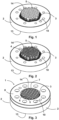
- Fig. 1 a perspective view of the body 2 of an extrusion tool 1 is shown with a first side 13 (not visible here) which has inlet openings 3, and a second side 14, via which material pressed into the extrusion tool 1 through the first side 13 can exit the extrusion tool 1 as an extrudate, wherein a surface for supporting a fastening element 8, a part of the internal structure and a second side 14 of the extrusion tool 1 can be seen.
- the surface for supporting the fastening element 8 has several passages 10, in particular in the form of bores, for receiving fastening means and positioning means, so that the body 2 can be aligned and fastened to an extrusion apparatus.
- FIG. 2 shows a perspective view of the extrusion tool 1 after further processing steps. It can be seen here that the individual depressions 5 are connected to one another by slots 4, whereby each depression 5 is directly connected to six adjacent depressions 5 via the slots 4. In order to be able to connect one depression 5 to all six adjacent depressions 5 with uniform alignment of the depressions 5, the introduction of slots 4, as shown, which are positioned at a 60° angle ⁇ , ⁇ to one another, has proven to be effective.
- inlet openings 3 do not only open into depressions 5 and their adjacent areas, but that inlet openings 3 are also provided which open exclusively into slots 4.
- both depressions 5 and slots 4 are evenly filled with plastic material, whereby a uniform deformation process of the plastic material can take place and a homogeneous extrudate can be created.
- a perspective view of a fully assembled extrusion tool 1 is shown, with a fastening element 8 now placed on top and elements inserted into the recesses 5 of the second side 14.
- the fastening element 8 is designed with a round opening 7 for the external limitation of the extrudate, which is why the extrusion tool 1 shown can be used to transform plastic material into an extrudate with a round cross-section and a large number of geometrically differently shaped and oriented cells. Consequently, the design of the cells is not only influenced by the Fig. 1 and 2 shown recesses 5 or slots 4 and their proportions and connections to one another, but also the elements designed as pins 6, which are inserted into the recesses 5.
- pins 6 are arranged centrally in the recesses 5 and are therefore positioned directly on the inlet opening 3, the central axis of which is arranged on a central axis of the recess 5.
- the inlet opening 3 can also allow the pin 6 to be attached and thus be closed and/or covered by it.
- the existing dimensioning of the pins 6, which are cylindrical and have a round cross-section, results in the plastic material being displaced from the recesses 5. Consequently, the recesses 5 no longer contribute to the pressure in the recesses 5 as in Fig. 1 and 2 to create a rod-shaped part of the extrudate, but now form a tubular part of the extrudate.
- the pins 6 are dimensioned such that a wall thickness of the resulting tubular parts of the extrudate corresponds to a slot width of the extrusion tool 1. Accordingly, with the geometry shown, the second side 14 of the extrusion tool 1, in contrast to the body 2 of the extrusion tool 1 according to Fig. 2 , an extrudate was obtained that had a significantly higher number of cells.
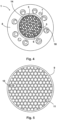
- Fig. 4 is a plan view of an extrusion tool 1 according to Fig. 3 shown, with a pin 6 inserted into a recess 5 of the extrusion tool 1.
- a pin 6 inserted into a recess 5 of the extrusion tool 1.
- the inlet openings 3 leading directly into the recesses 5 and the edge area of the extrudate created by the opening 7 of the fastening element 8 can be seen.
- Fig. 5 shows a schematic representation of the cell geometry of an extrudate with a round cross-section, which is produced with an extrusion tool 1 according to Fig. 3
- This illustration shows both a thick edge 9 of the extrudate produced by the fastening element 8 and its internal structure.
- the wall thickness of the round cells 11 is defined by a ratio of the diameters of pin 6 and recess 5
- the wall thickness of the polygonal cells 12 is defined by the width of the slots 4 in the second side 14 of the extrusion tool 1.
- the deviation from a hexagonal cell geometry is clearly visible due to the round cells 11 introduced, even though a hexagonal unit cell is also present.
- the depressions 5 are positioned at a distance of less than their own diameter, approximately half the diameter, from one another. This results in a particularly uniform geometric distribution of the cells within the extrudate, so that a flow velocity of gases passing through cells can be distributed almost evenly over the entire cross section of the extrudate.
- Fig. 6 shows a perspective view of part of the cell geometry of an extrudate with a square cross-section.
- the extrusion tool 1 can be adapted in such a way that inlet openings 3, depressions 5 and slots 4 must be extended over a square base area. If the round basic shape of an extrusion tool 1 is to be retained, an extrusion tool 1 according to Fig. 3 Furthermore, it is possible to change the opening 7 of the fastening element 8 to have a square cross-section. This allows the geometry of the extrudate created by recesses 5, slots 4 and pins 6 to be extended to a square base area.
- Fig. 7 a schematic representation of the unit cell of an extrudate produced with the extrusion tool 1 is shown. This shows the proportions between depressions 5, slots 4 and pins 6 in the form of a schematic unit cell.
- the distance between the depressions 5 and the angle ⁇ , ⁇ of the slots 4 to each other can be clearly identified. The latter is indicated by marking a first angle ⁇ between the slots 4 of the first direction 15 and second direction 16 and a second angle ⁇ between the slots 4 of the second direction 16 and third direction 17, both angles ⁇ , ⁇ having a size of 60°.
- the difference the diameter of recess 5 and pin 6 essentially corresponds to the width of slots 4.
- a method according to the invention enables the production of an extrusion tool 1 in a simple and efficient manner, which is composed of a few individual parts and has a special geometry, so that a deformation of plastic material into a carrier with a large surface and uniform distribution of flow resistance can be achieved.
Landscapes
- Engineering & Computer Science (AREA)
- Mechanical Engineering (AREA)
- Manufacturing & Machinery (AREA)
- Chemical & Material Sciences (AREA)
- Ceramic Engineering (AREA)
- Formation And Processing Of Food Products (AREA)
- Extrusion Moulding Of Plastics Or The Like (AREA)
Claims (15)
- Procédé, destiné à fabriquer un outil d'extrusion (1), lequel est apte à former un produit extrudé, en ce qu'une matière plastique est injectée sur un premier côté (13) dans l'outil d'extrusion (1), suite à quoi, après une déformation, la matière plastique sort d'un deuxième côté (14) hors de l'outil d'extrusion (1), dans le premier côté (13) d'un corps (2) étant ménagés des orifices d'entrée (3), dans le deuxième côté (14) du corps (2) étant ménagées des fentes (4), lesquelles relient les orifices d'entrée (3), caractérisé en ce que l'on ménage dans un deuxième côté (14) au moins un creux (5), lequel est relié avec les fentes (4) et les orifices d'entrée (3), suite à quoi, l'on place dans le creux (5) un élément, de telle sorte qu'une section transversale du produit extrudé formé avec l'outil d'extrusion (1) soit définie au moins partiellement par une géométrie des fentes (4), une géométrie des creux (5) et une géométrie de l'élément.
- Procédé selon la revendication 1, caractérisé en ce que les orifices d'entrée (3) et les creux (5) sont créés par fraisage et / ou par perçage au laser.
- Procédé selon la revendication 1 ou 2, caractérisé en ce que les fentes (4) sont créées par sciage ou par découpe, de préférence par découpe au laser ou par électroérosion, de manière particulièrement préférentielle, par électroérosion par fil.
- Procédé selon l'une quelconque des revendications 1 à 3, caractérisé en ce que l'on insère, l'on injecte et / ou l'on visse l'élément manuellement et / ou mécaniquement dans le creux (5).
- Procédé selon l'une quelconque des revendications 1 à 4, caractérisé en ce que l'on fixe l'élément par conjugaison de matières, notamment par collage ou par soudage dans le creux (5).
- Procédé selon l'une quelconque des revendications 1 à 5, caractérisé en ce que dans une première étape de procédé, l'on créé des orifices d'entrée (3), ainsi que des creux (5) et dans une deuxième étape de procédé, l'on créé les fentes (4), dans une troisième étape de procédé étant insérés les éléments.
- Outil d'extrusion (1), destiné à façonner une matière plastique, fabriqué notamment d'après un procédé selon les revendications 1 à 6, comprenant un corps (2) pourvu d'un premier côté (13) et d'une deuxième côté (14), le premier côté (13) comportant des orifices d'entrée (3) et le deuxième côté (14) comportant des fentes (4), lesquelles relient entre eux plusieurs orifices d'entrée (3), de telle sorte que le produit extrudé puisse être formé à l'aide de l'outil d'extrusion (1), en ce que l'on injecte une matière plastique par l'intermédiaire des orifices d'entrée (3) du premier côté (13) dans l'outil d'extrusion (1), laquelle matière plastique peut sortir après une déformation au moins partiellement par l'intermédiaire des fentes (4) du deuxième côté (14) hors de l'outil d'extrusion (1), caractérisé en ce que dans le deuxième côté (14) est prévu au moins un creux (5), lequel est relié avec les fentes (4) et les orifices d'entrée (3) et dans lequel est placé un élément, de telle sorte qu'une section transversale du produit extrudé soit définie au moins partiellement par une géométrie des fentes (4), une géométrie des creux (5) et une géométrie de l'élément.
- Outil d'extrusion (1) selon la revendication 7, caractérisé en ce que les creux (5) ont un diamètre supérieur à celui des orifices d'entrée (3).
- Outil d'extrusion (1) selon la revendication 7 ou 8, caractérisé en ce qu'au moins certains orifices d'entrée (3) débouchent directement dans le creux (5).
- Outil d'extrusion (1) selon l'une quelconque des revendications 7 à 9, caractérisé en ce que des axes médians des fentes (4) sont placés de telle sorte qu'ils recoupent des axes médians des creux (5) et des axes médians des orifices d'entrée (3).
- Outil d'extrusion (1) selon l'une quelconque des revendications 7 à 10, caractérisé en ce que l'élément est conçu en étant inférieur à une section transversale du creux (5), de telle sorte qu'entre l'élément et le creux (5) il reste un écart, lequel écart correspond de préférence à de 0,5 fois à 2 fois une largeur des fentes (4) .
- Outil d'extrusion (1) selon l'une quelconque des revendications 7 à 11, caractérisé en ce que l'écart entre deux creux (5) s'élève à de 25 % à 100 %, de préférence à 42 % du diamètre du creux (5).
- Outil d'extrusion (1) selon l'une quelconque des revendications 7 à 12, caractérisé en ce que des fentes (4) sont prévues, lesquelles sont placées le long d'une première direction (15) et le long d'une deuxième direction (16) sur le deuxième côté (14), la première direction (15) incluant avec la deuxième direction (16) un premier angle (α) de 40° à 120°, notamment d'environ 60°.
- Outil d'extrusion (1) selon l'une quelconque des revendications 7 à 13, caractérisé en ce que des fentes (4) sont prévues, lesquelles sont placées le long d'une troisième direction (17) sur le deuxième côté (14), la troisième direction (17) incluant avec la deuxième direction (16) un deuxième angle (β) de 40° à 120°, notamment d'environ 60°.
- Outil d'extrusion (1) selon l'une quelconque des revendications 7 à 14, caractérisé en ce que les éléments sont conçus avec une section transversale circulaire.
Priority Applications (1)
| Application Number | Priority Date | Filing Date | Title |
|---|---|---|---|
| EP21152685.0A EP4032680B1 (fr) | 2021-01-21 | 2021-01-21 | Procédé de fabrication d'un outil d'extrusion |
Applications Claiming Priority (1)
| Application Number | Priority Date | Filing Date | Title |
|---|---|---|---|
| EP21152685.0A EP4032680B1 (fr) | 2021-01-21 | 2021-01-21 | Procédé de fabrication d'un outil d'extrusion |
Publications (3)
| Publication Number | Publication Date |
|---|---|
| EP4032680A1 EP4032680A1 (fr) | 2022-07-27 |
| EP4032680B1 true EP4032680B1 (fr) | 2024-11-20 |
| EP4032680C0 EP4032680C0 (fr) | 2024-11-20 |
Family
ID=74194655
Family Applications (1)
| Application Number | Title | Priority Date | Filing Date |
|---|---|---|---|
| EP21152685.0A Active EP4032680B1 (fr) | 2021-01-21 | 2021-01-21 | Procédé de fabrication d'un outil d'extrusion |
Country Status (1)
| Country | Link |
|---|---|
| EP (1) | EP4032680B1 (fr) |
Citations (1)
| Publication number | Priority date | Publication date | Assignee | Title |
|---|---|---|---|---|
| US4955524A (en) * | 1989-08-24 | 1990-09-11 | General Motors Corporation | Extrusion die construction and its method of manufacture |
Family Cites Families (7)
| Publication number | Priority date | Publication date | Assignee | Title |
|---|---|---|---|---|
| US2908037A (en) * | 1954-03-24 | 1959-10-13 | Multiple Extrusions Inc | Making multiple tube structures by extrusion |
| JPS53137210A (en) * | 1977-05-04 | 1978-11-30 | Ngk Insulators Ltd | Dies for molding honeycombs |
| DE3919683A1 (de) | 1989-06-16 | 1991-01-17 | Huels Chemische Werke Ag | Extrusionsform zum extrudieren einer keramischen masse zu wabenkoerpern |
| EP1945583B1 (fr) * | 2005-10-12 | 2018-09-19 | Adelaide Research & Innovation Pty Ltd. | Procédé et dispositif pour former une fibre micro-structurée |
| DE102008009099A1 (de) * | 2008-02-14 | 2009-08-27 | Argillon Gmbh | Extrusionswerkzeug und Verfahren zur Herstellung eines Extrusionswerkzeugs |
| US11135740B2 (en) | 2015-03-06 | 2021-10-05 | Corning Incorporated | Extrusion dies and methods and apparatuses for forming the same |
| BE1023722B1 (de) * | 2015-11-13 | 2017-06-27 | Inexco Europe | Extrusionswerkzeug |
-
2021
- 2021-01-21 EP EP21152685.0A patent/EP4032680B1/fr active Active
Patent Citations (1)
| Publication number | Priority date | Publication date | Assignee | Title |
|---|---|---|---|---|
| US4955524A (en) * | 1989-08-24 | 1990-09-11 | General Motors Corporation | Extrusion die construction and its method of manufacture |
Also Published As
| Publication number | Publication date |
|---|---|
| EP4032680C0 (fr) | 2024-11-20 |
| EP4032680A1 (fr) | 2022-07-27 |
Similar Documents
| Publication | Publication Date | Title |
|---|---|---|
| DE3034068C2 (de) | Extrusionswerkzeug für die Herstellung von honigwaben-ähnlichen Profilen, insbesondere als Katalysatorträger, sowie Verfahren zu dessen Herstellung | |
| EP2898967B2 (fr) | Support d'outil de coupe, procédé de fabrication et utilisation d'un dispositif de fabrication génératif pour la fabrication d'un support d'outil de coupe | |
| EP2512743B1 (fr) | Dispositif de serrage pour profilés en forme de barres | |
| EP1321210B1 (fr) | Outil de chanfreinage | |
| EP1529584B1 (fr) | Manchon pour un mandrin et son procédé de fabrication | |
| WO2015165872A1 (fr) | Outil et procédé d'usinage par enlèvement de copeaux d'une pièce | |
| WO2021121468A1 (fr) | Foret hélicoïdal ayant une pointe de coupe munie d'une structure étagée | |
| DE10134826B4 (de) | Drahtzuführung in einer Federherstellvorrichtung | |
| WO2015166065A1 (fr) | Foret fabriqué à l'aide d'un procédé de frittage laser | |
| EP4032680B1 (fr) | Procédé de fabrication d'un outil d'extrusion | |
| DE4428813C2 (de) | Vorrichtung zum statischen Mischen von Fluiden, insbesondere von thermoplastifiziertem Kunststoff, und Verfahren zur Herstellung einer solchen Vorrichtung | |
| DE102012221135A1 (de) | Verfahren zum Herstellen einer Ventileinrichtung sowie entsprechende Ventileinrichtung | |
| DE2131633A1 (de) | Suspensionssieb und Verfahren zu seiner Herstellung | |
| EP3688220A1 (fr) | Procédé et dispositif de production d'un élément d'écoulement | |
| CH700756A2 (de) | Metallkreissägeblatt und Verwendung desselben, sowie Verfahren zum Herstellen von Rohrabschnitten. | |
| AT516506A4 (de) | Verfahren und Vorrichtung zum Schmieden eines stabförmigen Werkstücks | |
| EP0936053B1 (fr) | Elément court de calibration pour un dispositif de refroidissement et calibrage | |
| EP0730509A1 (fr) | Procede de production d'un outil a tranchants multiples | |
| DE102017118505B4 (de) | Verfahren zur Herstellung eines Aktivelements und entsprechendes Aktivelement | |
| LU101236B1 (de) | Verfahren zur Herstellung eines Bauteils für den Werkzeugbau und Haltewerkzeug zur Halterung eines Rohlings und eines Bauteils | |
| EP3746269A1 (fr) | Manchon de bras à ressort | |
| EP4389294A1 (fr) | Corps de buse à double jet | |
| BE1025471B1 (de) | Verfahren zur Herstellung eines Aktivelements und entsprechendes Aktivelement | |
| EP1057511A1 (fr) | Dispositif de tamisage | |
| DE102006015442A1 (de) | Elektrode zur elektrochemischen Bearbeitung von elektrisch leitfähigem Material |
Legal Events
| Date | Code | Title | Description |
|---|---|---|---|
| PUAI | Public reference made under article 153(3) epc to a published international application that has entered the european phase |
Free format text: ORIGINAL CODE: 0009012 |
|
| STAA | Information on the status of an ep patent application or granted ep patent |
Free format text: STATUS: THE APPLICATION HAS BEEN PUBLISHED |
|
| AK | Designated contracting states |
Kind code of ref document: A1 Designated state(s): AL AT BE BG CH CY CZ DE DK EE ES FI FR GB GR HR HU IE IS IT LI LT LU LV MC MK MT NL NO PL PT RO RS SE SI SK SM TR |
|
| STAA | Information on the status of an ep patent application or granted ep patent |
Free format text: STATUS: REQUEST FOR EXAMINATION WAS MADE |
|
| 17P | Request for examination filed |
Effective date: 20230113 |
|
| RBV | Designated contracting states (corrected) |
Designated state(s): AL AT BE BG CH CY CZ DE DK EE ES FI FR GB GR HR HU IE IS IT LI LT LU LV MC MK MT NL NO PL PT RO RS SE SI SK SM TR |
|
| GRAP | Despatch of communication of intention to grant a patent |
Free format text: ORIGINAL CODE: EPIDOSNIGR1 |
|
| STAA | Information on the status of an ep patent application or granted ep patent |
Free format text: STATUS: GRANT OF PATENT IS INTENDED |
|
| INTG | Intention to grant announced |
Effective date: 20240716 |
|
| RIC1 | Information provided on ipc code assigned before grant |
Ipc: B29L 31/60 20060101ALN20240708BHEP Ipc: B29C 48/30 20190101ALI20240708BHEP Ipc: B29C 48/32 20190101ALI20240708BHEP Ipc: B29C 48/345 20190101ALI20240708BHEP Ipc: B28B 3/26 20060101ALI20240708BHEP Ipc: B23P 15/24 20060101ALI20240708BHEP Ipc: B29C 48/11 20190101AFI20240708BHEP |
|
| GRAS | Grant fee paid |
Free format text: ORIGINAL CODE: EPIDOSNIGR3 |
|
| GRAA | (expected) grant |
Free format text: ORIGINAL CODE: 0009210 |
|
| STAA | Information on the status of an ep patent application or granted ep patent |
Free format text: STATUS: THE PATENT HAS BEEN GRANTED |
|
| AK | Designated contracting states |
Kind code of ref document: B1 Designated state(s): AL AT BE BG CH CY CZ DE DK EE ES FI FR GB GR HR HU IE IS IT LI LT LU LV MC MK MT NL NO PL PT RO RS SE SI SK SM TR |
|
| REG | Reference to a national code |
Ref country code: GB Ref legal event code: FG4D Free format text: NOT ENGLISH |
|
| REG | Reference to a national code |
Ref country code: CH Ref legal event code: EP |
|
| REG | Reference to a national code |
Ref country code: DE Ref legal event code: R096 Ref document number: 502021005832 Country of ref document: DE |
|
| REG | Reference to a national code |
Ref country code: IE Ref legal event code: FG4D Free format text: LANGUAGE OF EP DOCUMENT: GERMAN |
|
| U01 | Request for unitary effect filed |
Effective date: 20241210 |
|
| U07 | Unitary effect registered |
Designated state(s): AT BE BG DE DK EE FI FR IT LT LU LV MT NL PT RO SE SI Effective date: 20241219 |
|
| U20 | Renewal fee for the european patent with unitary effect paid |
Year of fee payment: 5 Effective date: 20250107 |
|
| PG25 | Lapsed in a contracting state [announced via postgrant information from national office to epo] |
Ref country code: HR Free format text: LAPSE BECAUSE OF FAILURE TO SUBMIT A TRANSLATION OF THE DESCRIPTION OR TO PAY THE FEE WITHIN THE PRESCRIBED TIME-LIMIT Effective date: 20241120 Ref country code: IS Free format text: LAPSE BECAUSE OF FAILURE TO SUBMIT A TRANSLATION OF THE DESCRIPTION OR TO PAY THE FEE WITHIN THE PRESCRIBED TIME-LIMIT Effective date: 20250320 |
|
| PG25 | Lapsed in a contracting state [announced via postgrant information from national office to epo] |
Ref country code: ES Free format text: LAPSE BECAUSE OF FAILURE TO SUBMIT A TRANSLATION OF THE DESCRIPTION OR TO PAY THE FEE WITHIN THE PRESCRIBED TIME-LIMIT Effective date: 20241120 |
|
| PG25 | Lapsed in a contracting state [announced via postgrant information from national office to epo] |
Ref country code: NO Free format text: LAPSE BECAUSE OF FAILURE TO SUBMIT A TRANSLATION OF THE DESCRIPTION OR TO PAY THE FEE WITHIN THE PRESCRIBED TIME-LIMIT Effective date: 20250220 |
|
| PG25 | Lapsed in a contracting state [announced via postgrant information from national office to epo] |
Ref country code: GR Free format text: LAPSE BECAUSE OF FAILURE TO SUBMIT A TRANSLATION OF THE DESCRIPTION OR TO PAY THE FEE WITHIN THE PRESCRIBED TIME-LIMIT Effective date: 20250221 |
|
| PG25 | Lapsed in a contracting state [announced via postgrant information from national office to epo] |
Ref country code: PL Free format text: LAPSE BECAUSE OF FAILURE TO SUBMIT A TRANSLATION OF THE DESCRIPTION OR TO PAY THE FEE WITHIN THE PRESCRIBED TIME-LIMIT Effective date: 20241120 |
|
| PG25 | Lapsed in a contracting state [announced via postgrant information from national office to epo] |
Ref country code: RS Free format text: LAPSE BECAUSE OF FAILURE TO SUBMIT A TRANSLATION OF THE DESCRIPTION OR TO PAY THE FEE WITHIN THE PRESCRIBED TIME-LIMIT Effective date: 20250220 |
|
| PG25 | Lapsed in a contracting state [announced via postgrant information from national office to epo] |
Ref country code: SM Free format text: LAPSE BECAUSE OF FAILURE TO SUBMIT A TRANSLATION OF THE DESCRIPTION OR TO PAY THE FEE WITHIN THE PRESCRIBED TIME-LIMIT Effective date: 20241120 |
|
| PG25 | Lapsed in a contracting state [announced via postgrant information from national office to epo] |
Ref country code: SK Free format text: LAPSE BECAUSE OF FAILURE TO SUBMIT A TRANSLATION OF THE DESCRIPTION OR TO PAY THE FEE WITHIN THE PRESCRIBED TIME-LIMIT Effective date: 20241120 |
|
| PG25 | Lapsed in a contracting state [announced via postgrant information from national office to epo] |
Ref country code: CZ Free format text: LAPSE BECAUSE OF FAILURE TO SUBMIT A TRANSLATION OF THE DESCRIPTION OR TO PAY THE FEE WITHIN THE PRESCRIBED TIME-LIMIT Effective date: 20241120 |
|
| REG | Reference to a national code |
Ref country code: CH Ref legal event code: PL |
|
| PG25 | Lapsed in a contracting state [announced via postgrant information from national office to epo] |
Ref country code: MC Free format text: LAPSE BECAUSE OF FAILURE TO SUBMIT A TRANSLATION OF THE DESCRIPTION OR TO PAY THE FEE WITHIN THE PRESCRIBED TIME-LIMIT Effective date: 20241120 |
|
| PLBE | No opposition filed within time limit |
Free format text: ORIGINAL CODE: 0009261 |
|
| STAA | Information on the status of an ep patent application or granted ep patent |
Free format text: STATUS: NO OPPOSITION FILED WITHIN TIME LIMIT |
|
| PG25 | Lapsed in a contracting state [announced via postgrant information from national office to epo] |
Ref country code: CH Free format text: LAPSE BECAUSE OF NON-PAYMENT OF DUE FEES Effective date: 20250131 |
|
| 26N | No opposition filed |
Effective date: 20250821 |
|
| PG25 | Lapsed in a contracting state [announced via postgrant information from national office to epo] |
Ref country code: IE Free format text: LAPSE BECAUSE OF NON-PAYMENT OF DUE FEES Effective date: 20250121 |
|
| U20 | Renewal fee for the european patent with unitary effect paid |
Year of fee payment: 6 Effective date: 20260119 |
|
| PGFP | Annual fee paid to national office [announced via postgrant information from national office to epo] |
Ref country code: GB Payment date: 20260123 Year of fee payment: 6 |