EP4032775B1 - Système de transport à câble - Google Patents
Système de transport à câble Download PDFInfo
- Publication number
- EP4032775B1 EP4032775B1 EP20868100.7A EP20868100A EP4032775B1 EP 4032775 B1 EP4032775 B1 EP 4032775B1 EP 20868100 A EP20868100 A EP 20868100A EP 4032775 B1 EP4032775 B1 EP 4032775B1
- Authority
- EP
- European Patent Office
- Prior art keywords
- track structure
- rail
- cords
- level
- trussed
- Prior art date
- Legal status (The legal status is an assumption and is not a legal conclusion. Google has not performed a legal analysis and makes no representation as to the accuracy of the status listed.)
- Active
Links
Images

Classifications
-
- B—PERFORMING OPERATIONS; TRANSPORTING
- B61—RAILWAYS
- B61B—RAILWAY SYSTEMS; EQUIPMENT THEREFOR NOT OTHERWISE PROVIDED FOR
- B61B5/00—Elevated railway systems without suspended vehicles
- B61B5/02—Elevated railway systems without suspended vehicles with two or more rails
-
- B—PERFORMING OPERATIONS; TRANSPORTING
- B61—RAILWAYS
- B61B—RAILWAY SYSTEMS; EQUIPMENT THEREFOR NOT OTHERWISE PROVIDED FOR
- B61B13/00—Other railway systems
-
- E—FIXED CONSTRUCTIONS
- E01—CONSTRUCTION OF ROADS, RAILWAYS, OR BRIDGES
- E01B—PERMANENT WAY; PERMANENT-WAY TOOLS; MACHINES FOR MAKING RAILWAYS OF ALL KINDS
- E01B2/00—General structure of permanent way
-
- E—FIXED CONSTRUCTIONS
- E01—CONSTRUCTION OF ROADS, RAILWAYS, OR BRIDGES
- E01B—PERMANENT WAY; PERMANENT-WAY TOOLS; MACHINES FOR MAKING RAILWAYS OF ALL KINDS
- E01B25/00—Tracks for special kinds of railways
-
- E—FIXED CONSTRUCTIONS
- E01—CONSTRUCTION OF ROADS, RAILWAYS, OR BRIDGES
- E01D—CONSTRUCTION OF BRIDGES, ELEVATED ROADWAYS OR VIADUCTS; ASSEMBLY OF BRIDGES
- E01D18/00—Bridges specially adapted for particular applications or functions not provided for elsewhere, e.g. aqueducts, bridges for supporting pipe-lines
-
- E—FIXED CONSTRUCTIONS
- E01—CONSTRUCTION OF ROADS, RAILWAYS, OR BRIDGES
- E01D—CONSTRUCTION OF BRIDGES, ELEVATED ROADWAYS OR VIADUCTS; ASSEMBLY OF BRIDGES
- E01D6/00—Truss-type bridges
Definitions
- the present invention relates to the above-ground transport systems of string type with rail track structure related to overpass-type tracks. It can be used in development of both inner-city highways and in construction of intercity and international transport systems.
- the logical solution to improve the existing track structures are the string transport systems by Yunitski.
- Linear transport system by Yunitski is known, see RU 2 080 268 C1 , which includes at least one vehicle having a drive unit and guided by wheels on at least one rail containing a head and connected to a prestressed longitudinal element mounted on supports located on foundation.
- Prestressed longitudinal element of this transport system is made in the form of at least one string connected by gaskets of variable height with head of each rail along the whole length.
- the rail head is connected to DC or AC electric power source, and the rail is connected to the support by means of electric insulator.
- Rails in the said transport system are connected to each other by means of transverse strips, which are equipped with electric insulators and dampers.
- the supports are rigid and movable, whereas the rail track is connected to the movable support by a mechanism of mutual relative longitudinal displacement, including, for example, with use of a rod, and/or a mechanism for adjusting its position relative to the support and foundation, and/or by means of a damper.
- Transport system by Yunitski which includes at least two pretensioned rail cords in the form of load-bearing members enclosed in bodies (casings) with rolling surfaces mating therewith, for vehicles.
- Rail cords form two track structures. Loaded and empty vehicles (see RU 2 475 386 C1 ) are installed on rail cords of track structures.
- both rail cords of each track are interconnected in spans between adjacent supports by means of two-level trussed track structure in the form of zigzag-oriented rod elements, forming triangles with lower and upper rail cords and located on the outer sides of those rail cords, wherein at each level of the track structure, left and right rail cords are connected to each other by cross bulkheads installed in junction units of rod elements and rail cords.
- a limitation to the wide use of the said transport system is the insufficient rigidity of its track structure, caused by the significant height of the track structure (considering the height of vehicles) relative to the width of its wheel track.
- the dynamic stability of the track structure in spans between the adjacent supports is also limited.
- the object of the invention is to solve the following technical tasks:
- RU 2224064 C1 in the name of the Applicant, discloses a transportation system comprising at least one main line secured on supports and made in form of prestressed power member enclosed in housing with mating rolling surface for running vehicles, and at least one auxiliary line with prestressed power member secured on supports at another level relative to the main line.
- Main and auxiliary lines are rigidly interconnected over entire span between adjacent supports by means of rod of crisscross orientated rod members whose longitudinal axes form triangles with longitudinal axes of main and auxiliary lines.
- main and auxiliary lines are arranged equidistantly over entire length of span, and auxiliary line secured under main line is provided with at least one side rolling surface.
- UA 71059 U discloses an elevated railway transport system that includes an overpass consisting of a series of interconnected elevated frames that rely on vertical supports, and made with box-shaped cross section formed by lateral, upper and lower structural elements of frames.
- Two supporting tracks are fixed on the structural elements of frame.
- Transport modules are mounted on rail tracks with possibility of oncoming traffic.
- Rail interchange systems are provided at the end sections of the overpass.
- the rail tracks are located on two levels - the lower track is mounted on the lower structural elements of frames.
- the upper track is mounted above the lower track on the upper structural elements of frames.
- the systems of rail interchange at the end sections of overpass are made in the form of a beam, which one end is pivotally secured on the support with possibility of turning the beam in the vertical plane of the track secured on the beam, as well as a drive for turning the beam in the position of joining the track of beam with the lower or upper track of elevated frame.
- JP 2006 096057 discloses a transportation system for a light user's case body.
- An aerial carriage is hung down by a high-tension thin steel plate hanger having a driving wheel.
- the technical aims are also achieved provided that the distance R, m, between the junction units of rod elements and rail cords of the lower level of the trussed track structure in each span is made multiple of the distance between the supports.
- Tackling the set tasks is also ensured by the fact that the assembly connection of the transverse beam with the support is made in the form of a pivot lever.
- the rail cord is current-carrying with the possibility of connection to a source of electric power of direct or alternating current.
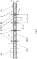
- the inventive string transport system by Yunitski as shown on Figure 1 , comprises two rail cords of lower 3 level mounted on the foundation 1 between the supports 2 (anchored 2a, resting on intermediate 2b), and two rail cords of upper 4 level of the track structure, arranged above them.
- Anchor supports 2a may be buildings and structures with specially equipped boarding and loading areas in the form of loading and unloading stations: passenger for passenger routes and cargo for freight routes (not shown on the Figures).
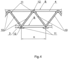
- Rail cords of the lower 3 and upper 4 levels of the track structure are made (see Figs. 1 and 4 ) in the form of prestressed load-bearing members 5 enclosed in the respective bodies 6 (see Fig. 3 ).
- one or more bundles made from high strength steel wire load-bearing elements may be used, either from rods assembled in a single bundle, or dispersed along the cross-section of the cavity (empty space) of the body 6, or one or more standard twisted or untwisted steel ropes, as well as cords, strips, bands or other extended elements made of any high-strength materials.
- the cavities in the body 6 between the elements of the load-bearing member 5 can be filled with a hardening material 7 based on polymer binders, composites, cement mixtures and/or similar hardening materials, which are rigidly connected into one piece by the load-bearing member 5 and the body 6 with its associated rolling surface 8 (see Figs. 1 and 4 ). concreting thereby as a whole the structure of the rail cord.
- the rolling surface 8 may be formed by the surface of the body 6 itself.
- the body 6 of the rail cord 3 and/or 4 may partially serve the functions of the prestressed load-bearing member 5, if it has also been stressed by tensioning during assembling of the structure.
- the rail cords of the lower 3 and upper 4 levels with mating therewith rolling surfaces 8 for the wheeled vehicles 9 and, accordingly, the tracks formed by them are made of an innovative modification - prestressed by tensioning in the longitudinal direction, those rail cords are load-bearing rigid beams of the lower and upper chords of the span arrangement (superstructure) of the two-level trussed track structure.
- FIG. 3 and 4 An image of cross section and fragment of frontal view of the span arrangement of the track structure of the proposed transport system (see Figs. 3 and 4 ) shows that the tracks of its rail cords of lower 3 and upper 4 levels are interconnected in the spans G between adjacent supports 2 into two-level trussed track structure by means of zigzag-oriented rod elements 10 forming triangles with the rail cords of the lower 3 and upper 4 levels.
- the left 3 L (4 L ) and, correspondingly, the right 3 P (4 P ) rail cords are connected to each other by cross bulkheads 11, which are installed in junction units 12 of zigzag-oriented rod elements 10 and rail cords (see Figs. 2 - 4 ), whereby zigzag-oriented rod elements 10 are placed on the outer sides of those rail cords, which ensures the formation of the profile of the two-level trussed track structure with minimal aerodynamic drag and high parameters of its rigidity (including torsional) and dynamic stability in the spans between adjacent supports 2.
- the length S , m, of the cross bulkhead 11 is defined as the distance between the vertical planes A and B of the respective junction units 12 of the zigzag-oriented rod elements 10 with the rail cords of the lower 3 and upper 4 levels of the track structure.
- the structural coupling (connection) of the cross bulkheads 11 to the bodies 6 of rail cords may be accomplished by any of the known methods: welding, riveting, threaded connection, gluing, kinematic engagement - through various guides made integral with mating elements located on the opposite ends of cross bulkheads 11, by attaching those opposite ends of cross bulkheads 11 to internal and/or external surfaces of bodies 6 of rail cords by various combinations of known joint methods (not shown on the Figures).
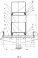
- Transverse beam 13 is fixed on support 2. It is essential that the transverse beam 13 is movably fastened along the longitudinal axis of the track structure by means of assembly units 14, which in turn are placed in two, respectively, left N and right M , vertical longitudinal planes.
- assembly units 14 which in turn are placed in two, respectively, left N and right M , vertical longitudinal planes.
- an important feature of the proposed transport system is that the rail cords of the lower 3 level of the two-level trussed track structure are connected to each other in the junction units 12 of the zigzag-oriented rod elements 10 by cross bulkheads 11, and fixed on the transverse beams 13 at the locations of those cross bulkheads 11 and the junction units 12 (see Fig. 3 ) by any known method, e.g. welding, or kinematically (not shown on the Figures).
- any of the non-limiting embodiments of the inventive string transport system various non-exclusive embodiments of the cross bulkhead 11 and its connection to the rail cords (in junction units 12) are feasible, one of which is shown on Figs. 3 and 4 .
- the spans G between the adjacent supports are made with a length multiple of the distance R , m, between the adjacent cross bulkheads 11 of the lower 3 level of the track structure, and between the assembly units 14 of the transverse beam 13, by means of (as an embodiment) fixing it in a certain position (in the vertical latitudinal plane W (see Fig.
- cross bulkhead 11 is installed in junction unit 12 of zigzag-oriented rod elements 10 of track structure of lower 3 level and is located along longitudinal axis X of transverse beam 13, whereby vertical planes A and B of arrangement of zigzag-oriented rod elements 10 are shifted relative to assembly units 14 of transverse beam 13 to its center, and distance L , m, from plane A ( B ) the arrangement of zigzag-oriented rod elements 10 of the trussed track structure up to assembly unit 14 of the transverse beam 13 (see Figs.
- Embodiment of the two-level trussed track structure with zigzag-oriented rod elements 10 located on its outer side and the arrangement of cross bulkheads 11 in junction units 12 of zigzag-oriented rod elements 10 of the trussed track structure when the terminal cross bulkhead 11 of the span structure is located and fixed along the longitudinal axis X of the transverse beam 13, for example, pivot-lever secured on the support 2, provides, if observed are the empirically obtained ratios of dimensions of the height H , m, of the trussed track structure, and distance L , m, from the plane of positioning of zigzag-oriented rod elements 10 of the trussed track structure up to corresponding assembly unit 14 of transverse beam 13, favorable redistribution of active loads and internal stresses in all structural elements of the two-level trussed track structure of the string transport system. This leads to a significant increase in the rigidity and dynamic stability of the trussed structure of the span arrangement of the track structure.
- the optimization of the support surface of the track structure plays a significant role, which, in turn, depends on the length K , m, of transverse beam 13, and height H , m, of two-level trussed track structure, defined by the dependencies: 0.02 ⁇ L / H ⁇ 0.5 , and 0.4 ⁇ S / K ⁇ 0.95 ,
- the values specified in the ratio (1) correspond to the optimal range of interdependence between the height H , m, of trussed track structure (and, accordingly, the height of the location of the center of mass of the span arrangement and the value of the support surface of such track structure.
- the ratio (1) is less than 0.02, then the dynamic stability of the span arrangement of the track structure is significantly reduced due to its low torsional rigidity.
- the ratio (1) is more than 0.5, then the material capacity of the entire structure, and therefore the cost of the transport system, are unjustifiably increased.
- the assembly units 14 of the transverse beam 13 are movable, for example, in the form of a pivot lever 15, a decrease in local overstresses in the rail cords of the track structure is attained, caused by temperature deformation and the impact of the wheeled vehicles 9, which, as a result, are redistributed along the entire length of the track of the proposed string transport system.
- the rail cord 3 (4) may be made current-carrying with the possibility of connection to a direct or alternating current electric power source. This will allow to electricize transport services and reduce environmental pollution.
- the rail cords 3 and 4 can be connected to the trussed track structure by means of electrical insulators, as well as that the trussed track structure can be made of an electric insulating (dielectric) material (not shown on the Figures).
- An alternative embodiment of the proposed string transport system is to provide the connection of rail cord 3 (4) with cross bulkhead 11 with electric insulators (not shown on the Figures) for isolating from each other the rail cords in each track, which increases the reliability, safety and efficiency of the entire system.
- cross bulkhead 11 is made of an electric insulating (dielectric) material.
- the cross bulkhead 11 is provided with a damper (not shown on the Figures).
- an electric insulator can be used as a damper.
- the transverse beam 13 may be connected to the string trussed track structure by an electric insulator (not shown).
- the transverse beam 13 may also be made of an electric insulating (dielectric) material.
- transverse beam 13 of the above dimensions pivot-lever connected to the support 2, and the corresponding positioning on the said transverse beam 13 of the cross bulkhead 11 of lower chord of the trussed span structure; through which, as an embodiment, it is connected to the transverse beam 13, and which is also made and installed in the structure in accordance with the parameters indicated above.
- the positioning of the cross bulkheads 11 between the rail cords 3 and 4 of the trussed structure of the span arrangement of the two-level trussed track structure is determined by the terms of request for proposal for the design thereof, according to which alternative versions of the proposed string transport system are possible, one variant of which is the implementation of spans G between adjacent supports 2 of length multiple of the distance R , m, between the junction units 12 of the zigzag-oriented rod elements 10 and the rail cords of the lower 3 level of the track structure.
- the distance R , m, between the junction units 12 of the zigzag-oriented rod elements 10 and the rail cords of the lower 3 level of the trussed track structure in each span G may be a multiple of the distance between the adjacent supports 2.
- trussed structures in various spans G can differ in spacing (not shown on the Figures) in positioning of their structural elements, for example, cross bulkheads 11.
- the construction of the represented string transport system by Yunitski includes installation on the foundation 1 of supports 2 and appropriately arranged and pivot-levered fixation thereon of transverse beams 13 of the specified length K , m, and the subsequent assembly in spans G between adjacent supports 2 of the span arrangements of the two-level trussed string track structure.
- lower and upper chords of this two-level trussed string track structure are constructed, each of them formed by left and right rail cords connected to each other by cross bulkheads 11 uniformly distributed in span G .
- the side faces of the two-level trussed string track structure are made in the form of zigzag-oriented rod elements 10 forming triangles with the rail cords of the lower 3 and upper 4 levels, and the junction units 12 of zigzag-oriented rod elements 10 with cross bulkheads 11 are arranged in respective vertical longitudinal planes A and B .
- the cross bulkheads 11 of the rail cords of the lower level 3 are arranged in a certain way on the transverse beams 13, fixed on those transverse beams 13 by any of the known methods, after which the rail cords 3 and 4 are equipped with wheeled vehicles 9, and the rail cords, which are made current-carrying, are connected to DC or AC electric power source.
- the string transport system by Yunitski of the described structure in the most general case of a variety of alternative embodiments, operates as described below.
- transverse beams 13 made with the above dimensions and properly fixed, increase the support surface of the two-level trussed track structure and reduce the influence of the tipping moment from the side of the rail cord of the upper level 4, when the wheeled vehicle 9 moves along it at its maximum load.
- the claimed arrangement of the string transport system by Yunitski proposed in the present technical approach allows to attain the intended targets and, at the same time, possesses a set of distinguishing features different from the known technical solutions, which meet the criteria of the invention "novelty” and “key distinctive features” (inventive step), which makes it possible to regard the proposed technical approach as inventive one.
Landscapes
- Engineering & Computer Science (AREA)
- Architecture (AREA)
- Civil Engineering (AREA)
- Structural Engineering (AREA)
- Mechanical Engineering (AREA)
- Transportation (AREA)
- Railway Tracks (AREA)
- Leg Units, Guards, And Driving Tracks Of Cranes (AREA)
- Electric Cable Arrangement Between Relatively Moving Parts (AREA)
- Rod-Shaped Construction Members (AREA)
Claims (4)
- Système de transport par câbles, comprenant une structure de voies ayant un niveau inférieur et un niveau supérieur, et comprenant deux câbles de rail (3) du niveau inférieur de la structure de voies et deux câbles de rail (4) du niveau supérieur de la structure de voies au-dessus d'eux,dans lequel les câbles de rail (3) du niveau inférieur sont montés sur une fondation (1) entre des supports d'ancrage (2a) et reposant sur des supports intermédiaires (2b), dans lequel les câbles de rail (3, 4) sont réalisés sous la forme d'éléments porteurs précontraints (5) enfermés dans des corps (6) correspondants des surfaces de roulement (8) correspondantes pour des véhicules à roues (9) etdans lequel les câbles de rail (3, 4) forment deux voies interconnectées dans des travées G entre des supports (2a, 2b) adjacents au moyen d'une structure de voies en treillis à deux niveau, sous la forme d'éléments tige (10) orientés en zigzag,dans lequel les éléments tige (10) orientés en zigzag forment des triangles avec les câbles de rail (3, 4) des niveaux inférieur et supérieur et sont positionnés sur les côtés extérieurs de ces câbles de rail (3, 4), dans lequel, en correspondance de chaque niveau de la structure de voies, les câbles de rail de droite et de gauche (3L, 3P, 4L, 4P) sont connectés entre-eux par des cloisons transversales (11) installées dans des unités de jonction (12) des éléments tige (10) et des câbles de rail (3, 4), caractérisé en ce que les câbles de rail (3) du niveau inférieur sont fixés sur des poutres transversales (13) entre des plans longitudinaux verticaux A et B passant à travers des unités de jonction (12) desdits éléments tige (10) orientés en zigzag,dans lequel les poutres transversales (13) sont connectées aux supports (2a, 2b) au moyen d'unités d'assemblage (14) situées dans deux plans longitudinaux verticaux N et M, avec la possibilité de se déplacer le long de la structure de voies,tandis que les poutres transversales (13) sont disposées en correspondance de points de sections par des plans longitudinaux W correspondants passant par des unités de jonction (12) et des centres de support (2a, 2b), tandis que les plans longitudinaux verticaux A et B, contenant des unités de jonction (12), sont déplacés par rapport aux unités d'assemblage (14) de la poutre transversale, vers son centre et d'une distance L définie par le rapport:
 où H - la hauteur de la structure de voies en treillis, par lequel la longueur S de la cloison transversale (11) et la longueur K de la poutre transversale (13) entre les unités d'assemblage (14) de la même sont liées par le rapport:
 par lequel la longueur des travées G est un multiple de la distance R entre les unités de jonction (12) des éléments tige et des câbles de rail (3) du niveau inférieur de la structure de voies en treillis.
 - Le système selon la revendication 1, caractérisé en ce que la distance R entre les unités de jonction (12) des éléments tige et des câbles de rail (3) du niveau inférieur de la structure de voies en treillis est un multiple de la distance entre les supports (2a, 2b) dans chaque travée G.
- Le système selon la revendication 1, caractérisé en ce que la connexion d'assemblage de la poutre transversale avec le support est réalisée sous forme de levier pivotant.
- Le système selon la revendication 1, caractérisé en ce que le câble de rail est porteur de courant, avec la possibilité de se connecter à une source d'énergie électrique de courant continu ou alternatif.
Applications Claiming Priority (2)
| Application Number | Priority Date | Filing Date | Title |
|---|---|---|---|
| EA201900541A EA038766B1 (ru) | 2019-09-25 | 2019-09-25 | Струнная транспортная система юницкого |
| PCT/BY2020/000012 WO2021056090A1 (fr) | 2019-09-25 | 2020-11-24 | Système de transport à câble |
Publications (4)
| Publication Number | Publication Date |
|---|---|
| EP4032775A1 EP4032775A1 (fr) | 2022-07-27 |
| EP4032775A4 EP4032775A4 (fr) | 2023-09-06 |
| EP4032775C0 EP4032775C0 (fr) | 2024-11-13 |
| EP4032775B1 true EP4032775B1 (fr) | 2024-11-13 |
Family
ID=75164727
Family Applications (1)
| Application Number | Title | Priority Date | Filing Date |
|---|---|---|---|
| EP20868100.7A Active EP4032775B1 (fr) | 2019-09-25 | 2020-11-24 | Système de transport à câble |
Country Status (4)
| Country | Link |
|---|---|
| EP (1) | EP4032775B1 (fr) |
| CN (1) | CN115427283B (fr) |
| EA (1) | EA038766B1 (fr) |
| WO (1) | WO2021056090A1 (fr) |
Families Citing this family (3)
| Publication number | Priority date | Publication date | Assignee | Title |
|---|---|---|---|---|
| EA037218B1 (ru) * | 2019-01-04 | 2021-02-20 | Анатолий Эдуардович Юницкий | Струнная транспортная система юницкого |
| CN114808558B (zh) * | 2022-04-13 | 2024-08-16 | 山东启和云梭物流科技有限公司 | 一种复合异型翼缘轨道系统 |
| US12479667B1 (en) | 2024-07-26 | 2025-11-25 | Anatoli Eduardovich Unitsky | Cargo transport complex |
Family Cites Families (16)
| Publication number | Priority date | Publication date | Assignee | Title |
|---|---|---|---|---|
| JPH0224259A (ja) * | 1988-07-13 | 1990-01-26 | Toyo Electric Mfg Co Ltd | 自動循環式索道の出発・到着押送装置 |
| FR2701242B1 (fr) * | 1993-02-08 | 1995-04-28 | Pomagalski Sa | Installation de transport en site propre à plusieurs sections de voie. |
| CN1167467A (zh) * | 1994-04-08 | 1997-12-10 | Ntl新运输系统股份有限公司 | 线性运输系统 |
| WO1995027643A1 (fr) | 1994-04-08 | 1995-10-19 | Ntl Neue Transportlinien Gmbh | Systeme de transport en ligne |
| DE19646121A1 (de) * | 1996-11-08 | 1998-05-14 | Rudolf Berger | Leichtgasgetragenes Transportmittel |
| RU2224064C1 (ru) * | 2002-05-21 | 2004-02-20 | Юницкий Анатолий Эдуардович | Транспортная система юницкого (варианты) и способ построения транспортной системы |
| JP2006096057A (ja) * | 2004-09-28 | 2006-04-13 | Masao Honda | 高架軌道輸送・交通システム |
| CN101549692A (zh) * | 2008-04-01 | 2009-10-07 | 欧淼森 | 轻型无人驾驶式电动车辆及立体带电车道 |
| CN101935978B (zh) * | 2010-08-16 | 2013-02-13 | 同济大学 | 索轨高架及其专用轨道行车 |
| CN102463994B (zh) * | 2010-11-15 | 2014-11-12 | 盐城海旭数控装备有限公司 | 一种双层双向路轨兼容绿色公交系统 |
| RU2475386C1 (ru) | 2011-08-31 | 2013-02-20 | Анатолий Эдуардович Юницкий | Транспортная система юницкого и способ построения струнной транспортной системы |
| RU2520983C2 (ru) * | 2011-09-08 | 2014-06-27 | Анатолий Эдуардович Юницкий | Транспортная система юницкого |
| UA71059U (uk) * | 2012-03-23 | 2012-06-25 | Семен Моисеевич Месонжник | Естакадна фермова система рейкового транспорту |
| CN104213477A (zh) * | 2014-09-22 | 2014-12-17 | 中铁工程设计咨询集团有限公司 | 跨座式单轨双箱矩形钢-混结合轨道梁结构 |
| IT201800006234A1 (it) * | 2018-06-12 | 2019-12-12 | Impianto di trasporto a fune | |
| CN211547106U (zh) * | 2020-01-19 | 2020-09-22 | 羿鹏轨道交通开发(上海)有限公司 | 一种悬挂式单轨交通用轨道梁 |
-
2019
- 2019-09-25 EA EA201900541A patent/EA038766B1/ru unknown
-
2020
- 2020-11-24 WO PCT/BY2020/000012 patent/WO2021056090A1/fr not_active Ceased
- 2020-11-24 EP EP20868100.7A patent/EP4032775B1/fr active Active
- 2020-11-24 CN CN202080081946.9A patent/CN115427283B/zh not_active Expired - Fee Related
Also Published As
| Publication number | Publication date |
|---|---|
| CN115427283A (zh) | 2022-12-02 |
| EP4032775C0 (fr) | 2024-11-13 |
| EP4032775A4 (fr) | 2023-09-06 |
| CN115427283B (zh) | 2024-06-11 |
| EP4032775A1 (fr) | 2022-07-27 |
| WO2021056090A1 (fr) | 2021-04-01 |
| EA038766B1 (ru) | 2021-10-15 |
| EA201900541A1 (ru) | 2021-03-31 |
Similar Documents
| Publication | Publication Date | Title |
|---|---|---|
| EP4032775B1 (fr) | Système de transport à câble | |
| Daly et al. | Strengthening of bridges using external post-tensioning | |
| US5119731A (en) | Station on a railway or other line, situated on a viaduct | |
| CN109653077B (zh) | 一种三主缆双塔柱悬索桥 | |
| CN101935978B (zh) | 索轨高架及其专用轨道行车 | |
| EP3560786B1 (fr) | Systeme de transport | |
| CN115397712B (zh) | 运输系统 | |
| CN112770955B (zh) | 尤尼茨基的运输系统及其制造及组装方法 | |
| EP3992049B1 (fr) | Système de transport | |
| EP3907117B1 (fr) | Systeme de transport de type câble | |
| EP3395637B1 (fr) | Système de communications | |
| CN111417558B (zh) | 串式轨道结构 | |
| EP3617024B1 (fr) | Système de voie et de rails à treillis | |
| CN113957755A (zh) | 一种中低速磁浮交通组合u形梁结构 | |
| CN116200976B (zh) | 一种大跨度跨座式单轨轨道梁及其施工方法 | |
| CN104912365B (zh) | 一种狭窄场地立体停车架 | |
| US20220205196A1 (en) | EA Box Girder System | |
| CN120575477A (zh) | 用于高铁的桥梁结构及施工方法 | |
| CA2457630A1 (fr) | Poutre composite et procede de fabrication de celle-ci | |
| Shivakumar | Strengthening of existing timber stringer bridges by the addition of steel stringers | |
| Leland et al. | Rehabilitation study of Toutle river tied-arch bridges |
Legal Events
| Date | Code | Title | Description |
|---|---|---|---|
| STAA | Information on the status of an ep patent application or granted ep patent |
Free format text: STATUS: THE INTERNATIONAL PUBLICATION HAS BEEN MADE |
|
| PUAI | Public reference made under article 153(3) epc to a published international application that has entered the european phase |
Free format text: ORIGINAL CODE: 0009012 |
|
| STAA | Information on the status of an ep patent application or granted ep patent |
Free format text: STATUS: REQUEST FOR EXAMINATION WAS MADE |
|
| 17P | Request for examination filed |
Effective date: 20220421 |
|
| AK | Designated contracting states |
Kind code of ref document: A1 Designated state(s): AL AT BE BG CH CY CZ DE DK EE ES FI FR GB GR HR HU IE IS IT LI LT LU LV MC MK MT NL NO PL PT RO RS SE SI SK SM TR |
|
| XX | Miscellaneous (additional remarks) |
Free format text: THE FILING DATE OF THE INTERNATIONAL APPLICATION IS WITHIN TWO MONTHS FROM THE DATE OF EXPIRATION OF THE PRIORITY PERIOD (R. 26BIS.3 PCT). |
|
| A4 | Supplementary search report drawn up and despatched |
Effective date: 20230803 |
|
| RIC1 | Information provided on ipc code assigned before grant |
Ipc: E01D 18/00 20060101ALI20230728BHEP Ipc: E01D 6/00 20060101ALI20230728BHEP Ipc: E01B 25/00 20060101ALI20230728BHEP Ipc: B61B 13/00 20060101ALI20230728BHEP Ipc: B61B 5/02 20060101AFI20230728BHEP |
|
| DAV | Request for validation of the european patent (deleted) | ||
| DAX | Request for extension of the european patent (deleted) | ||
| RAP3 | Party data changed (applicant data changed or rights of an application transferred) |
Owner name: UNITSKY, ANATOLI EDUARDOVICH |
|
| RIN1 | Information on inventor provided before grant (corrected) |
Inventor name: UNITSKY, ANATOLI EDUARDOVICH |
|
| GRAP | Despatch of communication of intention to grant a patent |
Free format text: ORIGINAL CODE: EPIDOSNIGR1 |
|
| STAA | Information on the status of an ep patent application or granted ep patent |
Free format text: STATUS: GRANT OF PATENT IS INTENDED |
|
| INTG | Intention to grant announced |
Effective date: 20240711 |
|
| GRAS | Grant fee paid |
Free format text: ORIGINAL CODE: EPIDOSNIGR3 |
|
| GRAA | (expected) grant |
Free format text: ORIGINAL CODE: 0009210 |
|
| STAA | Information on the status of an ep patent application or granted ep patent |
Free format text: STATUS: THE PATENT HAS BEEN GRANTED |
|
| AK | Designated contracting states |
Kind code of ref document: B1 Designated state(s): AL AT BE BG CH CY CZ DE DK EE ES FI FR GB GR HR HU IE IS IT LI LT LU LV MC MK MT NL NO PL PT RO RS SE SI SK SM TR |
|
| REG | Reference to a national code |
Ref country code: GB Ref legal event code: FG4D |
|
| XX | Miscellaneous (additional remarks) |
Free format text: THE FILING DATE OF THE INTERNATIONAL APPLICATION IS WITHIN TWO MONTHS FROM THE DATE OF EXPIRATION OF THE PRIORITY PERIOD (R. 26BIS.3 PCT). |
|
| REG | Reference to a national code |
Ref country code: CH Ref legal event code: EP |
|
| REG | Reference to a national code |
Ref country code: IE Ref legal event code: FG4D |
|
| REG | Reference to a national code |
Ref country code: DE Ref legal event code: R096 Ref document number: 602020041464 Country of ref document: DE |
|
| U01 | Request for unitary effect filed |
Effective date: 20241205 |
|
| U07 | Unitary effect registered |
Designated state(s): AT BE BG DE DK EE FI FR IT LT LU LV MT NL PT RO SE SI Effective date: 20241213 |
|
| U20 | Renewal fee for the european patent with unitary effect paid |
Year of fee payment: 5 Effective date: 20250305 |
|
| PG25 | Lapsed in a contracting state [announced via postgrant information from national office to epo] |
Ref country code: IS Free format text: LAPSE BECAUSE OF FAILURE TO SUBMIT A TRANSLATION OF THE DESCRIPTION OR TO PAY THE FEE WITHIN THE PRESCRIBED TIME-LIMIT Effective date: 20250313 Ref country code: HR Free format text: LAPSE BECAUSE OF FAILURE TO SUBMIT A TRANSLATION OF THE DESCRIPTION OR TO PAY THE FEE WITHIN THE PRESCRIBED TIME-LIMIT Effective date: 20241113 |
|
| PG25 | Lapsed in a contracting state [announced via postgrant information from national office to epo] |
Ref country code: ES Free format text: LAPSE BECAUSE OF FAILURE TO SUBMIT A TRANSLATION OF THE DESCRIPTION OR TO PAY THE FEE WITHIN THE PRESCRIBED TIME-LIMIT Effective date: 20241113 |
|
| PG25 | Lapsed in a contracting state [announced via postgrant information from national office to epo] |
Ref country code: NO Free format text: LAPSE BECAUSE OF FAILURE TO SUBMIT A TRANSLATION OF THE DESCRIPTION OR TO PAY THE FEE WITHIN THE PRESCRIBED TIME-LIMIT Effective date: 20250213 |
|
| PG25 | Lapsed in a contracting state [announced via postgrant information from national office to epo] |
Ref country code: GR Free format text: LAPSE BECAUSE OF FAILURE TO SUBMIT A TRANSLATION OF THE DESCRIPTION OR TO PAY THE FEE WITHIN THE PRESCRIBED TIME-LIMIT Effective date: 20250214 |
|
| PG25 | Lapsed in a contracting state [announced via postgrant information from national office to epo] |
Ref country code: PL Free format text: LAPSE BECAUSE OF FAILURE TO SUBMIT A TRANSLATION OF THE DESCRIPTION OR TO PAY THE FEE WITHIN THE PRESCRIBED TIME-LIMIT Effective date: 20241113 |
|
| PG25 | Lapsed in a contracting state [announced via postgrant information from national office to epo] |
Ref country code: RS Free format text: LAPSE BECAUSE OF FAILURE TO SUBMIT A TRANSLATION OF THE DESCRIPTION OR TO PAY THE FEE WITHIN THE PRESCRIBED TIME-LIMIT Effective date: 20250213 |
|
| REG | Reference to a national code |
Ref country code: CH Ref legal event code: PL |
|
| PG25 | Lapsed in a contracting state [announced via postgrant information from national office to epo] |
Ref country code: SM Free format text: LAPSE BECAUSE OF FAILURE TO SUBMIT A TRANSLATION OF THE DESCRIPTION OR TO PAY THE FEE WITHIN THE PRESCRIBED TIME-LIMIT Effective date: 20241113 |
|
| REG | Reference to a national code |
Ref country code: CH Ref legal event code: PL |
|
| PG25 | Lapsed in a contracting state [announced via postgrant information from national office to epo] |
Ref country code: CH Free format text: LAPSE BECAUSE OF NON-PAYMENT OF DUE FEES Effective date: 20241130 |
|
| PG25 | Lapsed in a contracting state [announced via postgrant information from national office to epo] |
Ref country code: SK Free format text: LAPSE BECAUSE OF FAILURE TO SUBMIT A TRANSLATION OF THE DESCRIPTION OR TO PAY THE FEE WITHIN THE PRESCRIBED TIME-LIMIT Effective date: 20241113 |
|
| PG25 | Lapsed in a contracting state [announced via postgrant information from national office to epo] |
Ref country code: CZ Free format text: LAPSE BECAUSE OF FAILURE TO SUBMIT A TRANSLATION OF THE DESCRIPTION OR TO PAY THE FEE WITHIN THE PRESCRIBED TIME-LIMIT Effective date: 20241113 |
|
| PG25 | Lapsed in a contracting state [announced via postgrant information from national office to epo] |
Ref country code: MC Free format text: LAPSE BECAUSE OF FAILURE TO SUBMIT A TRANSLATION OF THE DESCRIPTION OR TO PAY THE FEE WITHIN THE PRESCRIBED TIME-LIMIT Effective date: 20241113 |
|
| PLBE | No opposition filed within time limit |
Free format text: ORIGINAL CODE: 0009261 |
|
| STAA | Information on the status of an ep patent application or granted ep patent |
Free format text: STATUS: NO OPPOSITION FILED WITHIN TIME LIMIT |
|
| 26N | No opposition filed |
Effective date: 20250814 |
|
| PG25 | Lapsed in a contracting state [announced via postgrant information from national office to epo] |
Ref country code: IE Free format text: LAPSE BECAUSE OF NON-PAYMENT OF DUE FEES Effective date: 20241124 |
|
| GBPC | Gb: european patent ceased through non-payment of renewal fee |
Effective date: 20250213 |
|
| PG25 | Lapsed in a contracting state [announced via postgrant information from national office to epo] |
Ref country code: GB Free format text: LAPSE BECAUSE OF NON-PAYMENT OF DUE FEES Effective date: 20250213 |
|
| PG25 | Lapsed in a contracting state [announced via postgrant information from national office to epo] |
Ref country code: HU Free format text: LAPSE BECAUSE OF FAILURE TO SUBMIT A TRANSLATION OF THE DESCRIPTION OR TO PAY THE FEE WITHIN THE PRESCRIBED TIME-LIMIT; INVALID AB INITIO Effective date: 20201124 |
|
| PG25 | Lapsed in a contracting state [announced via postgrant information from national office to epo] |
Ref country code: CY Free format text: LAPSE BECAUSE OF FAILURE TO SUBMIT A TRANSLATION OF THE DESCRIPTION OR TO PAY THE FEE WITHIN THE PRESCRIBED TIME-LIMIT; INVALID AB INITIO Effective date: 20201124 |