EP4032794A1 - Structure de manivelle et ensemble de manivelles de bicyclette à effort réduit - Google Patents
Structure de manivelle et ensemble de manivelles de bicyclette à effort réduit Download PDFInfo
- Publication number
- EP4032794A1 EP4032794A1 EP22151465.6A EP22151465A EP4032794A1 EP 4032794 A1 EP4032794 A1 EP 4032794A1 EP 22151465 A EP22151465 A EP 22151465A EP 4032794 A1 EP4032794 A1 EP 4032794A1
- Authority
- EP
- European Patent Office
- Prior art keywords
- shaft
- crank
- gear
- rotation
- disposed
- Prior art date
- Legal status (The legal status is an assumption and is not a legal conclusion. Google has not performed a legal analysis and makes no representation as to the accuracy of the status listed.)
- Granted
Links
Images





Classifications
-
- B—PERFORMING OPERATIONS; TRANSPORTING
- B62—LAND VEHICLES FOR TRAVELLING OTHERWISE THAN ON RAILS
- B62M—RIDER PROPULSION OF WHEELED VEHICLES OR SLEDGES; POWERED PROPULSION OF SLEDGES OR SINGLE-TRACK CYCLES; TRANSMISSIONS SPECIALLY ADAPTED FOR SUCH VEHICLES
- B62M3/00—Construction of cranks operated by hand or foot
- B62M3/003—Combination of crank axles and bearings housed in the bottom bracket
-
- B—PERFORMING OPERATIONS; TRANSPORTING
- B62—LAND VEHICLES FOR TRAVELLING OTHERWISE THAN ON RAILS
- B62M—RIDER PROPULSION OF WHEELED VEHICLES OR SLEDGES; POWERED PROPULSION OF SLEDGES OR SINGLE-TRACK CYCLES; TRANSMISSIONS SPECIALLY ADAPTED FOR SUCH VEHICLES
- B62M3/00—Construction of cranks operated by hand or foot
- B62M3/02—Construction of cranks operated by hand or foot of adjustable length
- B62M3/04—Construction of cranks operated by hand or foot of adjustable length automatically adjusting
-
- B—PERFORMING OPERATIONS; TRANSPORTING
- B62—LAND VEHICLES FOR TRAVELLING OTHERWISE THAN ON RAILS
- B62M—RIDER PROPULSION OF WHEELED VEHICLES OR SLEDGES; POWERED PROPULSION OF SLEDGES OR SINGLE-TRACK CYCLES; TRANSMISSIONS SPECIALLY ADAPTED FOR SUCH VEHICLES
- B62M1/00—Rider propulsion of wheeled vehicles
- B62M1/36—Rider propulsion of wheeled vehicles with rotary cranks, e.g. with pedal cranks
-
- B—PERFORMING OPERATIONS; TRANSPORTING
- B62—LAND VEHICLES FOR TRAVELLING OTHERWISE THAN ON RAILS
- B62M—RIDER PROPULSION OF WHEELED VEHICLES OR SLEDGES; POWERED PROPULSION OF SLEDGES OR SINGLE-TRACK CYCLES; TRANSMISSIONS SPECIALLY ADAPTED FOR SUCH VEHICLES
- B62M11/00—Transmissions characterised by the use of interengaging toothed wheels or frictionally-engaging wheels
- B62M11/02—Transmissions characterised by the use of interengaging toothed wheels or frictionally-engaging wheels of unchangeable ratio
-
- B—PERFORMING OPERATIONS; TRANSPORTING
- B62—LAND VEHICLES FOR TRAVELLING OTHERWISE THAN ON RAILS
- B62M—RIDER PROPULSION OF WHEELED VEHICLES OR SLEDGES; POWERED PROPULSION OF SLEDGES OR SINGLE-TRACK CYCLES; TRANSMISSIONS SPECIALLY ADAPTED FOR SUCH VEHICLES
- B62M3/00—Construction of cranks operated by hand or foot
-
- B—PERFORMING OPERATIONS; TRANSPORTING
- B62—LAND VEHICLES FOR TRAVELLING OTHERWISE THAN ON RAILS
- B62M—RIDER PROPULSION OF WHEELED VEHICLES OR SLEDGES; POWERED PROPULSION OF SLEDGES OR SINGLE-TRACK CYCLES; TRANSMISSIONS SPECIALLY ADAPTED FOR SUCH VEHICLES
- B62M3/00—Construction of cranks operated by hand or foot
- B62M2003/006—Crank arrangements to overcome dead points
Definitions
- the present disclosure relates to a crank structure technology of a bicycle, particularly to an effort-saving crank structure and assembly of a bicycle.
- a crank of a related-art bicycle is a rod member with a fixed length and used for connecting a treadle and a central shaft of the bicycle.
- the user pedals the treadle to make a circular motion be performed with the length of the crank as a radius and the central shaft of the treadle as a rotation center, and driving devices, for example gear disks, a chain, of the bicycle are driven to make the bicycle to forwardly move.
- the crank may not be prolonged for increasing a length of a force arm when the treadle is rotated to a position where an external force is required to be applied, thus an effect of increasing the moment may not be provided.
- the design of retractable crank does not comply with the ergonomics and a circular motion with regularity and inertia may not be performed. As such, it is an effort-wasting design, and the structure of the treadle crank device is complicated and may cause the user to be tired easily.
- the present disclosure is to provide an effort-saving crank structure and assembly of a bicycle, in which an effort-saving effect may be achieved by a force applying arm consisted of a rotation arm unit and a crank, thus a simple structure is provided and a stable transmission may be established through a circular motion.
- the present disclosure provides an effort-saving crank structure of a bicycle, which includes a crank mechanism, a transmission mechanism, and a rotation arm unit.
- the crank mechanism has a crank, a shaft end gear disposed on one end of the crank and a treadle end gear disposed on another end of the crank.
- the transmission mechanism is disposed in the crank and has a rotation shaft and a first gear and a second gear connected to two ends of the rotation shaft, the first gear and the shaft end gear are engaged for transmission, and the second gear and the treadle end gear are engaged for transmission.
- the rotation arm unit has a first rotation arm and a second rotation arm, and two ends of the second rotation arm are respectively connected to one end of the first rotation arm and the treadle end gear.
- the present disclosure provides an effort-saving crank assembly of a bicycle
- the bicycle has a central shaft engage seat
- the effort-saving crank assembly includes a central shaft, a set of effort-saving crank structures and a set of abutting members.
- the central shaft is disposed in the central shaft engage seat.
- Each of the effort-saving crank structures is connected to one end of the central shaft, and each of the effort-saving crank structures has a crank mechanism, a transmission mechanism, and a rotation arm unit.
- the crank mechanism has a crank, a shaft end gear disposed on one end of the crank and a treadle end gear connected to another end of the crank.
- the transmission mechanism is disposed in the crank and has a rotation shaft and a first gear and a second gear disposed at two ends of the rotation shaft, the first gear and the shaft end gear are engaged for transmissions, and the second gear and the treadle end gear are engaged for transmissions.
- the rotation arm unit has a first rotation arm and a second rotation arm, and two ends of the second rotation arm are respectively connected to one end of the first rotation arm and the treadle end gear.
- Each of the abutting members is adapted to sheathe each of the shaft end gears and located between each of the cranks and the central shaft engage seat.
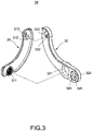
- the present disclosure provides an effort-saving crank structure of a bicycle, the crank structure mainly includes a crank mechanism 10, a transmission mechanism 20 and a rotation arm unit 30.
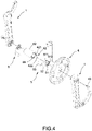
- the crank mechanism 10 mainly includes a crank 11, a shaft end gear 12 and a treadle end gear 13.
- the crank 11 mainly includes an outer housing 111 and an inner housing 116, one end of the outer housing 111 is extended with a round column 112 and another end of the outer housing 111 is formed with a first connection hole 113, and an accommodation slot A is formed in the outer housing 111 and located between the round column 112 and the first connection hole 113.
- a plurality of screw holes 114 are evenly distributed at a periphery of an inner surface of the outer housing 111, and a rectangular conical hole 115 is formed in the round column 112.
- a shape of the inner housing 116 is corresponding to a shape of the outer housing 111.
- One end of the inner housing 116 is formed with a second connection hole 117, and another end of the inner housing 116 is formed with a shaft sleeve 118, and the shaft sleeve 118 is disposed corresponding to the first connection hole 113.
- a convex rib B is extended in the inner housing 116 and located between the second connection hole 117 and the shaft sleeve 118, and the convex rib B is mounted and fastened corresponding to the accommodation slot A.
- a plurality of penetrated holes 119 are evenly distributed at a periphery of the inner housing 116, and each of the penetrated holes 119 is disposed corresponding to each of the screw holes 114 to allow a fastening member C, for example a screw, to pass and lock.
- the shaft end gear 12 is a fixed gear (i.e., being fixed and not rotary), adapted to sheathe the round column 112 and received in the second connection hole 117 to make the shaft end gear 12 be supported between the round column 112 and the inner housing 113.
- a plurality of bevel inclined teeth 121 are annularly disposed on one side of the shaft end gear 12, and a plurality of mounting strips 122 are disposed on another side of the shaft end gear 12 away from each of the bevel inclined teeth 121.
- the treadle end gear 13 is a rotary gear (i.e., being driven by the transmission mechanism 20 to rotate during the crank 11 is operated to be rotated).
- a front end and a rear end of the treadle end gear 13 are respectively extended with a front convex column 131 and a rear convex column 132.
- the front convex column 131 is disposed corresponding to the first connection hole 113
- the rear convex column 132 is jointly disposed in the shaft sleeve 118 with a bearing 14 to make the treadle end gear 13 be supported between the outer housing 111 and the inner housing 116.
- a plurality of bevel inclined teeth 133 are annularly disposed on one side of the treadle end gear 13, the front convex column 131 of the treadle end gear 13 has a positioning plane 134, and an end surface of the front convex column 131 has two positioning holes 135.
- the transmission mechanism 20 is disposed in the crank 11, and mainly includes a rotation shaft 21, a first gear 22 and a second gear 23.
- the first gear 22 and the second gear 23 are connected to two ends of the rotation shaft 21, and the first gear 22 and the second gear 23 are both a bevel gear.
- the first gear 22 and the shaft end gear 12 are engaged for transmission, and the second gear 23 and the treadle end gear 13 are engaged for transmission.
- a gear ratio of the first gear 22 and the shaft end gear 12 is 1: 3
- a gear ratio of the second gear 23 and the treadle end gear 13 is 1: 3 to provide a desirable transmission
- gear teeth of the treadle end gear 13 may be equal to or smaller than gear teeth of the shaft end gear 12.
- the transmission mechanism 20 further includes a connection shaft sleeve 24, a plurality of fixed shaft sleeves 25 and a plurality of positioning shaft sleeves 26.
- the rotation shaft 21 includes a first rotation shaft 211 and a second rotation shaft 212.
- the first gear 22 is connected to one end of the first rotation shaft 211
- the second gear 23 is connected to one end of the second rotation shaft 212
- the connection shaft sleeve 24 is adapted to sheathe another end of the first rotation shaft 211 and another end of the second rotation shaft 212
- the connection shaft sleeve 24 is rotated with the first rotation shaft 211 and the second rotation shaft 212.
- the fixed shaft sleeves 25 are adapted to sheathe the first rotation shaft 211 and the second rotation shaft 212 at intervals, and fixedly disposed between the convex rib B of the inner housing 116 and the accommodation slot A of the outer housing 111.
- Each of the positioning shaft sleeves 26 are adapted to sheathe the first rotation shaft 211 and the second rotation shaft 212 at intervals, and disposed between any two of the adjacent fixed shaft sleeves 25.
- the rotation arm unit 30 includes a first rotation arm 31 and a second rotation arm 32.
- the first rotation arm 31 and the second rotation arm 32 are both an arc-shaped rotation arm.
- the first rotation arm 31 is formed between the crank 11 and the second rotation arm 32, and has a treadle connecting column 311, and another end of the first rotation arm 31 away from the treadle connecting column 311 is disposed with a sleeve slot 312 and an insertion block 313.
- the second rotation arm 32 has a penetrated hole 321, and one end thereof away from the penetrated hole 321 is disposed with a mounting block 322 and an engage slot 323.
- the treadle connecting column 311 is disposed in the penetrated hole 321, and the engage slot 323 and the mounting block 322 are correspondingly combined with the insertion block 313 and the sleeve slot 312 of the first rotation arm 31.
- a mounting slot 324 is formed at a lateral side of the penetrated hole 321 and located at an inner side of the second rotation arm 32, a latching plane 325 is formed in the mounting slot 324, and the second rotation arm 32 has two through holes 326 communicating with the mounting slot 324.
- the front convex column 131 is disposed in the mounting slot 324, the latching plane 325 of the second rotation arm 32 and the positioning plane 134 of the front convex column 131 are mutually latched, and each of the positioning holes 135 of the front convex column 131 is disposed corresponding to each of the through holes 326 to allow a fastening member, for example a screw, to pass and locked.
- the present invention also provides an effort-saving crank assembly mainly including a central shaft 4, a set of effort-saving crank structures 1 and a set of abutting members 5.
- the central shaft 4 mainly includes a main shaft segment 41 and an extending segment 42 outwardly extended from two ends of the main shaft segment 41.
- the extending segment 42 has a rectangular conical column 421 to allow the round column 112 to sheathe and be combined via the rectangular conical hole 115.
- An end surface of the extending segment 42 has a screw hole 422 to allow a screw bolt 43 to pass and lock.
- Each of the abutting members 5 mainly includes a ring member 51, an arm member 52 extended from the ring member 51 and an abutting rod 53 connected to one end of the arm member 52 away from the ring member 51.
- a plurality of mounting protrusions 511 are disposed at an outer periphery of the ring member 51, a plurality of mounting slots 512 are disposed on an inner circumferential wall of the ring member 51, and each of the insertion strips 122 of the shaft end gear 12 is mounted in each of the mounting slots 512.
- the effort-saving crank assembly of the present disclosure further includes a chain wheel 6 adapted to sheathe the round column 112 of the shaft end gear 12 and disposed between one of the cranks 11 and one of the abutting members 5.
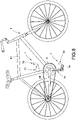
- FIG. 8 and FIG. 9 disclose the effort-saving crank assembly of the present disclosure being applied in a bicycle 8.
- the bicycle 8 includes a frame 81, a central shaft engage seat 82 disposed at a bottom end of the frame 81, a left fork 83 extended from the central shaft engage seat 82 toward a direction of a rear wheel and a right fork 84 formed at a right side of the left fork 83.
- the bicycle 8 further includes a set of treadles 85, a set of mounting rings 86 and other necessary components.
- the central shaft 4 When being assembled, the central shaft 4 is inserted in the central shaft engage seat 82, each of the mounting rings 86 is locked on the central shaft engage seat 82 to limit the central shaft 4 in the central shaft engage seat 82, and the central shaft 4 may be rotated in the central shaft engage seat 82.
- Each of the abutting members 5 is correspondingly mounted and positioned with each of the mounting rings 86 to make each of the abutting members 5 be located at two sides of the central shaft engage seat 82, the abutting rod 53 of the abutting member 5 at the left side abuts against a bottom edge of the left fork 83, and the abutting rod 53 of the abutting member 5 at the right side abuts against a top edge of the right fork 84.
- the rectangular conical column 421 of the central shaft 4 is sheathed by the rectangular conical hole 115 of the round column 112, and each of the insertion strips 122 of the shaft end gear 12 is correspondingly mounted and combined with each of the mounting slots 512 of the ring member 51.
- the screw bolt 43 is utilized to pass the round column 112 of the crank 11 and correspondingly locked in the screw hole 422 of the central shaft 4. As such, the central shaft 4 may be driven by rotations of the crank 11 to generate rotating motions.
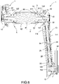
- a force applying arm defined at connecting locations of a shaft core of the shaft end gear 12 to the first rotation arm 31 and to the second rotation arm 32 is greater than a length of the crank 11.
- M force applying arm defined at connecting locations of a shaft core of the shaft end gear 12 to the first rotation arm 31 and to the second rotation arm 32
- F action force
- d moment arm
- the crank mechanism 10 drives the central shaft 4 and the chain wheel 6 to rotate with the crank 11 via the round column 121.
- the rotation arm unit 30 downwardly rotates from an apex position, the first gear 22 is driven by the shaft end gear 12 to make the rotation shaft 21 and the second gear 23 be driven to generate rotations, and the treadle end gear 13 is driven through the second gear 23, thus a constant angle defined between the rotation arm unit 30 and the ground may be kept, a motion track at a center of the treadle 85 forms a motion similar to a circular motion.
- a moving direction of the rotation arm unit 30 is opposite to a moving direction of the crank 11.
Landscapes
- Engineering & Computer Science (AREA)
- Chemical & Material Sciences (AREA)
- Combustion & Propulsion (AREA)
- Transportation (AREA)
- Mechanical Engineering (AREA)
- Transmission Devices (AREA)
- Motorcycle And Bicycle Frame (AREA)
- Steering Devices For Bicycles And Motorcycles (AREA)
- Fittings On The Vehicle Exterior For Carrying Loads, And Devices For Holding Or Mounting Articles (AREA)
- Shafts, Cranks, Connecting Bars, And Related Bearings (AREA)
- Automatic Cycles, And Cycles In General (AREA)
Applications Claiming Priority (1)
| Application Number | Priority Date | Filing Date | Title |
|---|---|---|---|
| TW110102157A TWI801798B (zh) | 2021-01-20 | 2021-01-20 | 自行車之省力型曲柄結構及總成 |
Publications (3)
| Publication Number | Publication Date |
|---|---|
| EP4032794A1 true EP4032794A1 (fr) | 2022-07-27 |
| EP4032794C0 EP4032794C0 (fr) | 2023-11-22 |
| EP4032794B1 EP4032794B1 (fr) | 2023-11-22 |
Family
ID=79602114
Family Applications (1)
| Application Number | Title | Priority Date | Filing Date |
|---|---|---|---|
| EP22151465.6A Active EP4032794B1 (fr) | 2021-01-20 | 2022-01-13 | Structure de manivelle et ensemble de manivelles de bicyclette à effort réduit |
Country Status (8)
| Country | Link |
|---|---|
| US (1) | US11548588B2 (fr) |
| EP (1) | EP4032794B1 (fr) |
| JP (1) | JP3236735U (fr) |
| KR (1) | KR20220001856U (fr) |
| AU (1) | AU2022200269B2 (fr) |
| BR (1) | BR202022000905U2 (fr) |
| GB (1) | GB2604445B (fr) |
| TW (1) | TWI801798B (fr) |
Cited By (1)
| Publication number | Priority date | Publication date | Assignee | Title |
|---|---|---|---|---|
| EP4434868A1 (fr) * | 2023-03-21 | 2024-09-25 | Hsuan-Chih Lin | Appareil à manivelle équipé d'un mécanisme d'économie de travail et ensemble manivelle de bicyclette |
Families Citing this family (1)
| Publication number | Priority date | Publication date | Assignee | Title |
|---|---|---|---|---|
| DE102023000029B4 (de) | 2023-01-09 | 2024-09-26 | Josef Nagerl | Pedalantrieb mit Umlaufrädergetriebe |
Citations (4)
| Publication number | Priority date | Publication date | Assignee | Title |
|---|---|---|---|---|
| CH225699A (de) * | 1942-02-14 | 1943-02-15 | Magus A G | Tretkurbelgetriebe für Fahrräder. |
| FR1002832A (fr) * | 1949-12-15 | 1952-03-11 | Manivelle amplificatrice de puissance particulièrement applicable aux bîcyclettes | |
| CN207015537U (zh) * | 2017-05-26 | 2018-02-16 | 林暄智 | 人力车的可省力踩踏曲柄装置 |
| CN111434574A (zh) * | 2019-01-15 | 2020-07-21 | 李峻丞 | 人力车的可增力踩踏曲柄装置 |
Family Cites Families (12)
| Publication number | Priority date | Publication date | Assignee | Title |
|---|---|---|---|---|
| US627086A (en) * | 1899-06-20 | Bicycle propulsion | ||
| CH680465A5 (en) | 1991-11-28 | 1992-08-31 | Jaroslav Stekl | Constant torque crank mechanism |
| US6830259B2 (en) * | 2003-02-05 | 2004-12-14 | Petar Jakovljevic | Pedal-type driving device suitable for bicycle |
| WO2005032925A2 (fr) * | 2003-09-29 | 2005-04-14 | Ascher Steven G | Bicyclette a geometrie de cadre, chemin de pedalage elliptique et configuration de siege permettant d'ameliorer l'efficacite et le confort |
| US7520196B2 (en) * | 2005-04-29 | 2009-04-21 | Gregory Keith Stallard | Power cranks |
| US20100175947A1 (en) * | 2009-01-15 | 2010-07-15 | Chen-Ching Chang | Chainless transmission mechanism for bicycle |
| US20120167709A1 (en) * | 2011-01-03 | 2012-07-05 | Kung-Cheng Chen | Length adjustable bicycle crank |
| FR3042774A1 (fr) | 2015-10-27 | 2017-04-28 | Robert Edet | Systeme de manivelles de pedalier de cycle permettant d'augmenter le bras de levier et de supprimer les points morts sans modifier l'amplitude du deplacement circulaire des pedales |
| CN105947090A (zh) * | 2016-04-26 | 2016-09-21 | 李辉 | 一种周转恒向的自行车脚踏 |
| TWM549189U (zh) * | 2017-05-22 | 2017-09-21 | Hsuan-Chih Lin | 人力車之可省力踩踏曲柄結構 |
| CN108928425A (zh) * | 2017-05-26 | 2018-12-04 | 林暄智 | 人力车的可省力踩踏曲柄装置 |
| DE202018003342U1 (de) * | 2018-07-18 | 2018-10-29 | Felix Schmidt | Kurbeltrieb mit periodischer Änderung der wirksamen Hebellänge |
-
2021
- 2021-01-20 TW TW110102157A patent/TWI801798B/zh active
-
2022
- 2022-01-13 US US17/575,229 patent/US11548588B2/en active Active
- 2022-01-13 EP EP22151465.6A patent/EP4032794B1/fr active Active
- 2022-01-14 JP JP2022000089U patent/JP3236735U/ja active Active
- 2022-01-17 KR KR2020220000126U patent/KR20220001856U/ko not_active Ceased
- 2022-01-17 AU AU2022200269A patent/AU2022200269B2/en active Active
- 2022-01-18 BR BR202022000905-3U patent/BR202022000905U2/pt unknown
- 2022-01-20 GB GB2200692.8A patent/GB2604445B/en active Active
Patent Citations (4)
| Publication number | Priority date | Publication date | Assignee | Title |
|---|---|---|---|---|
| CH225699A (de) * | 1942-02-14 | 1943-02-15 | Magus A G | Tretkurbelgetriebe für Fahrräder. |
| FR1002832A (fr) * | 1949-12-15 | 1952-03-11 | Manivelle amplificatrice de puissance particulièrement applicable aux bîcyclettes | |
| CN207015537U (zh) * | 2017-05-26 | 2018-02-16 | 林暄智 | 人力车的可省力踩踏曲柄装置 |
| CN111434574A (zh) * | 2019-01-15 | 2020-07-21 | 李峻丞 | 人力车的可增力踩踏曲柄装置 |
Cited By (3)
| Publication number | Priority date | Publication date | Assignee | Title |
|---|---|---|---|---|
| EP4434868A1 (fr) * | 2023-03-21 | 2024-09-25 | Hsuan-Chih Lin | Appareil à manivelle équipé d'un mécanisme d'économie de travail et ensemble manivelle de bicyclette |
| GB2634978A (en) * | 2023-03-21 | 2025-04-30 | Hsuan Chih Lin | Crank apparatus equipped with labor-saving mechanism and bicycle crank assembly |
| US12466515B2 (en) | 2023-03-21 | 2025-11-11 | Hsuan-Chih Lin | Crank apparatus equipped with labor-saving mechanism and bicycle crank assembly |
Also Published As
| Publication number | Publication date |
|---|---|
| JP3236735U (ja) | 2022-03-11 |
| US20220227453A1 (en) | 2022-07-21 |
| EP4032794C0 (fr) | 2023-11-22 |
| GB202200692D0 (en) | 2022-03-09 |
| TWI801798B (zh) | 2023-05-11 |
| KR20220001856U (ko) | 2022-07-27 |
| AU2022200269A1 (en) | 2022-08-04 |
| BR202022000905U2 (pt) | 2023-02-07 |
| AU2022200269B2 (en) | 2024-08-08 |
| US11548588B2 (en) | 2023-01-10 |
| EP4032794B1 (fr) | 2023-11-22 |
| GB2604445B (en) | 2024-11-13 |
| TW202229090A (zh) | 2022-08-01 |
| GB2604445A (en) | 2022-09-07 |
Similar Documents
| Publication | Publication Date | Title |
|---|---|---|
| CN1077668C (zh) | 自行车用内装变速装置 | |
| EP4032794A1 (fr) | Structure de manivelle et ensemble de manivelles de bicyclette à effort réduit | |
| US5407409A (en) | Exerciser with friction-type resistance device | |
| US5551718A (en) | Pedal mechanism for cycle and exercise equipment | |
| WO2004101353A1 (fr) | Unite d'entrainement de bicyclette capable de deplacement vers l'arriere, de rotation nulle, et de deplacement vers l'avant en cas de rectitude ou de retropedalage | |
| US20060264287A1 (en) | Bicycle drive unit of multi pedaling type | |
| KR19990077750A (ko) | 자전거의 주행 및 가속장치 | |
| CN111434574A (zh) | 人力车的可增力踩踏曲柄装置 | |
| JP4040653B2 (ja) | クランク装置、それを備えた乗り物用クランクペダル装置、及びそれらを備えた乗り物 | |
| US12195135B2 (en) | Crank variable-speed gear device for increasing rotational power | |
| KR850000591B1 (ko) | 자전거 변속기 | |
| CN114802578B (zh) | 自行车的省力型曲柄结构及总成 | |
| TWM614613U (zh) | 自行車之省力型曲柄結構及總成 | |
| EP4434868B1 (fr) | Appareil à manivelle équipé d'un mécanisme d'économie de travail, bicyclette et utilisation d'une paire desdits appareils à manivelle dans une bicyclette | |
| JPH1170889A (ja) | 自転車のペダリング機構 | |
| KR100356734B1 (ko) | 자전거의 역구동 페달링 장치 | |
| KR100491483B1 (ko) | 일방향 동력전달 장치 | |
| KR102251943B1 (ko) | 회전력을 증가시키기 위한 크랭크 가변속 기어장치 | |
| KR200226194Y1 (ko) | 자전거의 페달을 이용한 추진장치 | |
| US20160347404A1 (en) | Transmission System for a Bicycle | |
| CN118683677A (zh) | 具有省力机制的曲柄装置及自行车曲柄总成 | |
| JPS6224315B2 (fr) | ||
| JPH0712836B2 (ja) | 自動無段変速装置 |
Legal Events
| Date | Code | Title | Description |
|---|---|---|---|
| PUAI | Public reference made under article 153(3) epc to a published international application that has entered the european phase |
Free format text: ORIGINAL CODE: 0009012 |
|
| STAA | Information on the status of an ep patent application or granted ep patent |
Free format text: STATUS: THE APPLICATION HAS BEEN PUBLISHED |
|
| AK | Designated contracting states |
Kind code of ref document: A1 Designated state(s): AL AT BE BG CH CY CZ DE DK EE ES FI FR GB GR HR HU IE IS IT LI LT LU LV MC MK MT NL NO PL PT RO RS SE SI SK SM TR |
|
| STAA | Information on the status of an ep patent application or granted ep patent |
Free format text: STATUS: REQUEST FOR EXAMINATION WAS MADE |
|
| 17P | Request for examination filed |
Effective date: 20221201 |
|
| RBV | Designated contracting states (corrected) |
Designated state(s): AL AT BE BG CH CY CZ DE DK EE ES FI FR GB GR HR HU IE IS IT LI LT LU LV MC MK MT NL NO PL PT RO RS SE SI SK SM TR |
|
| STAA | Information on the status of an ep patent application or granted ep patent |
Free format text: STATUS: EXAMINATION IS IN PROGRESS |
|
| 17Q | First examination report despatched |
Effective date: 20230321 |
|
| GRAP | Despatch of communication of intention to grant a patent |
Free format text: ORIGINAL CODE: EPIDOSNIGR1 |
|
| STAA | Information on the status of an ep patent application or granted ep patent |
Free format text: STATUS: GRANT OF PATENT IS INTENDED |
|
| RIC1 | Information provided on ipc code assigned before grant |
Ipc: B62M 1/36 20130101ALI20230810BHEP Ipc: B62M 3/00 20060101ALI20230810BHEP Ipc: B62M 3/04 20060101AFI20230810BHEP |
|
| INTG | Intention to grant announced |
Effective date: 20230912 |
|
| GRAS | Grant fee paid |
Free format text: ORIGINAL CODE: EPIDOSNIGR3 |
|
| GRAA | (expected) grant |
Free format text: ORIGINAL CODE: 0009210 |
|
| STAA | Information on the status of an ep patent application or granted ep patent |
Free format text: STATUS: THE PATENT HAS BEEN GRANTED |
|
| AK | Designated contracting states |
Kind code of ref document: B1 Designated state(s): AL AT BE BG CH CY CZ DE DK EE ES FI FR GB GR HR HU IE IS IT LI LT LU LV MC MK MT NL NO PL PT RO RS SE SI SK SM TR |
|
| REG | Reference to a national code |
Ref country code: GB Ref legal event code: FG4D |
|
| REG | Reference to a national code |
Ref country code: CH Ref legal event code: EP |
|
| REG | Reference to a national code |
Ref country code: DE Ref legal event code: R096 Ref document number: 602022001024 Country of ref document: DE |
|
| REG | Reference to a national code |
Ref country code: IE Ref legal event code: FG4D |
|
| U01 | Request for unitary effect filed |
Effective date: 20231218 |
|
| U07 | Unitary effect registered |
Designated state(s): AT BE BG DE DK EE FI FR IT LT LU LV MT NL PT SE SI Effective date: 20231222 |
|
| U20 | Renewal fee for the european patent with unitary effect paid |
Year of fee payment: 3 Effective date: 20240131 |
|
| PG25 | Lapsed in a contracting state [announced via postgrant information from national office to epo] |
Ref country code: GR Free format text: LAPSE BECAUSE OF FAILURE TO SUBMIT A TRANSLATION OF THE DESCRIPTION OR TO PAY THE FEE WITHIN THE PRESCRIBED TIME-LIMIT Effective date: 20240223 |
|
| PG25 | Lapsed in a contracting state [announced via postgrant information from national office to epo] |
Ref country code: IS Free format text: LAPSE BECAUSE OF FAILURE TO SUBMIT A TRANSLATION OF THE DESCRIPTION OR TO PAY THE FEE WITHIN THE PRESCRIBED TIME-LIMIT Effective date: 20240322 |
|
| PG25 | Lapsed in a contracting state [announced via postgrant information from national office to epo] |
Ref country code: ES Free format text: LAPSE BECAUSE OF FAILURE TO SUBMIT A TRANSLATION OF THE DESCRIPTION OR TO PAY THE FEE WITHIN THE PRESCRIBED TIME-LIMIT Effective date: 20231122 |
|
| PG25 | Lapsed in a contracting state [announced via postgrant information from national office to epo] |
Ref country code: IS Free format text: LAPSE BECAUSE OF FAILURE TO SUBMIT A TRANSLATION OF THE DESCRIPTION OR TO PAY THE FEE WITHIN THE PRESCRIBED TIME-LIMIT Effective date: 20240322 Ref country code: GR Free format text: LAPSE BECAUSE OF FAILURE TO SUBMIT A TRANSLATION OF THE DESCRIPTION OR TO PAY THE FEE WITHIN THE PRESCRIBED TIME-LIMIT Effective date: 20240223 Ref country code: ES Free format text: LAPSE BECAUSE OF FAILURE TO SUBMIT A TRANSLATION OF THE DESCRIPTION OR TO PAY THE FEE WITHIN THE PRESCRIBED TIME-LIMIT Effective date: 20231122 |
|
| PG25 | Lapsed in a contracting state [announced via postgrant information from national office to epo] |
Ref country code: RS Free format text: LAPSE BECAUSE OF FAILURE TO SUBMIT A TRANSLATION OF THE DESCRIPTION OR TO PAY THE FEE WITHIN THE PRESCRIBED TIME-LIMIT Effective date: 20231122 Ref country code: PL Free format text: LAPSE BECAUSE OF FAILURE TO SUBMIT A TRANSLATION OF THE DESCRIPTION OR TO PAY THE FEE WITHIN THE PRESCRIBED TIME-LIMIT Effective date: 20231122 Ref country code: NO Free format text: LAPSE BECAUSE OF FAILURE TO SUBMIT A TRANSLATION OF THE DESCRIPTION OR TO PAY THE FEE WITHIN THE PRESCRIBED TIME-LIMIT Effective date: 20240222 Ref country code: HR Free format text: LAPSE BECAUSE OF FAILURE TO SUBMIT A TRANSLATION OF THE DESCRIPTION OR TO PAY THE FEE WITHIN THE PRESCRIBED TIME-LIMIT Effective date: 20231122 |
|
| PG25 | Lapsed in a contracting state [announced via postgrant information from national office to epo] |
Ref country code: CZ Free format text: LAPSE BECAUSE OF FAILURE TO SUBMIT A TRANSLATION OF THE DESCRIPTION OR TO PAY THE FEE WITHIN THE PRESCRIBED TIME-LIMIT Effective date: 20231122 |
|
| PG25 | Lapsed in a contracting state [announced via postgrant information from national office to epo] |
Ref country code: SK Free format text: LAPSE BECAUSE OF FAILURE TO SUBMIT A TRANSLATION OF THE DESCRIPTION OR TO PAY THE FEE WITHIN THE PRESCRIBED TIME-LIMIT Effective date: 20231122 |
|
| PG25 | Lapsed in a contracting state [announced via postgrant information from national office to epo] |
Ref country code: SM Free format text: LAPSE BECAUSE OF FAILURE TO SUBMIT A TRANSLATION OF THE DESCRIPTION OR TO PAY THE FEE WITHIN THE PRESCRIBED TIME-LIMIT Effective date: 20231122 Ref country code: SK Free format text: LAPSE BECAUSE OF FAILURE TO SUBMIT A TRANSLATION OF THE DESCRIPTION OR TO PAY THE FEE WITHIN THE PRESCRIBED TIME-LIMIT Effective date: 20231122 Ref country code: RO Free format text: LAPSE BECAUSE OF FAILURE TO SUBMIT A TRANSLATION OF THE DESCRIPTION OR TO PAY THE FEE WITHIN THE PRESCRIBED TIME-LIMIT Effective date: 20231122 Ref country code: CZ Free format text: LAPSE BECAUSE OF FAILURE TO SUBMIT A TRANSLATION OF THE DESCRIPTION OR TO PAY THE FEE WITHIN THE PRESCRIBED TIME-LIMIT Effective date: 20231122 |
|
| REG | Reference to a national code |
Ref country code: DE Ref legal event code: R097 Ref document number: 602022001024 Country of ref document: DE |
|
| PG25 | Lapsed in a contracting state [announced via postgrant information from national office to epo] |
Ref country code: MC Free format text: LAPSE BECAUSE OF FAILURE TO SUBMIT A TRANSLATION OF THE DESCRIPTION OR TO PAY THE FEE WITHIN THE PRESCRIBED TIME-LIMIT Effective date: 20231122 |
|
| PG25 | Lapsed in a contracting state [announced via postgrant information from national office to epo] |
Ref country code: MC Free format text: LAPSE BECAUSE OF FAILURE TO SUBMIT A TRANSLATION OF THE DESCRIPTION OR TO PAY THE FEE WITHIN THE PRESCRIBED TIME-LIMIT Effective date: 20231122 |
|
| PLBE | No opposition filed within time limit |
Free format text: ORIGINAL CODE: 0009261 |
|
| STAA | Information on the status of an ep patent application or granted ep patent |
Free format text: STATUS: NO OPPOSITION FILED WITHIN TIME LIMIT |
|
| 26N | No opposition filed |
Effective date: 20240823 |
|
| REG | Reference to a national code |
Ref country code: GB Ref legal event code: S29 Free format text: OFFER FILED; APPLICATION FILED 30 SEPTEMBER 2024 |
|
| PG25 | Lapsed in a contracting state [announced via postgrant information from national office to epo] |
Ref country code: IE Free format text: LAPSE BECAUSE OF NON-PAYMENT OF DUE FEES Effective date: 20240113 |
|
| PG25 | Lapsed in a contracting state [announced via postgrant information from national office to epo] |
Ref country code: IE Free format text: LAPSE BECAUSE OF NON-PAYMENT OF DUE FEES Effective date: 20240113 |
|
| U20 | Renewal fee for the european patent with unitary effect paid |
Year of fee payment: 4 Effective date: 20250131 |
|
| REG | Reference to a national code |
Ref country code: GB Ref legal event code: S29 Free format text: OFFER ACCEPTED |
|
| PG25 | Lapsed in a contracting state [announced via postgrant information from national office to epo] |
Ref country code: GB Free format text: LAPSE BECAUSE OF THE APPLICANT RENOUNCES Effective date: 20250416 |
|
| PG25 | Lapsed in a contracting state [announced via postgrant information from national office to epo] |
Ref country code: CY Free format text: LAPSE BECAUSE OF FAILURE TO SUBMIT A TRANSLATION OF THE DESCRIPTION OR TO PAY THE FEE WITHIN THE PRESCRIBED TIME-LIMIT; INVALID AB INITIO Effective date: 20220113 |
|
| REG | Reference to a national code |
Ref country code: CH Ref legal event code: PL |
|
| PG25 | Lapsed in a contracting state [announced via postgrant information from national office to epo] |
Ref country code: CH Free format text: LAPSE BECAUSE OF NON-PAYMENT OF DUE FEES Effective date: 20250131 |
|
| PG25 | Lapsed in a contracting state [announced via postgrant information from national office to epo] |
Ref country code: TR Free format text: LAPSE BECAUSE OF FAILURE TO SUBMIT A TRANSLATION OF THE DESCRIPTION OR TO PAY THE FEE WITHIN THE PRESCRIBED TIME-LIMIT Effective date: 20231122 |