EP4032847A1 - Système de commande de grue empileuse - Google Patents
Système de commande de grue empileuse Download PDFInfo
- Publication number
- EP4032847A1 EP4032847A1 EP22152255.0A EP22152255A EP4032847A1 EP 4032847 A1 EP4032847 A1 EP 4032847A1 EP 22152255 A EP22152255 A EP 22152255A EP 4032847 A1 EP4032847 A1 EP 4032847A1
- Authority
- EP
- European Patent Office
- Prior art keywords
- swaying
- height
- mast
- detection
- amount
- Prior art date
- Legal status (The legal status is an assumption and is not a legal conclusion. Google has not performed a legal analysis and makes no representation as to the accuracy of the status listed.)
- Granted
Links
Images


Classifications
-
- B—PERFORMING OPERATIONS; TRANSPORTING
- B65—CONVEYING; PACKING; STORING; HANDLING THIN OR FILAMENTARY MATERIAL
- B65G—TRANSPORT OR STORAGE DEVICES, e.g. CONVEYORS FOR LOADING OR TIPPING, SHOP CONVEYOR SYSTEMS OR PNEUMATIC TUBE CONVEYORS
- B65G1/00—Storing articles, individually or in orderly arrangement, in warehouses or magazines
- B65G1/02—Storage devices
- B65G1/04—Storage devices mechanical
- B65G1/0407—Storage devices mechanical using stacker cranes
- B65G1/0421—Storage devices mechanical using stacker cranes with control for stacker crane operations
-
- B—PERFORMING OPERATIONS; TRANSPORTING
- B66—HOISTING; LIFTING; HAULING
- B66F—HOISTING, LIFTING, HAULING OR PUSHING, NOT OTHERWISE PROVIDED FOR, e.g. DEVICES WHICH APPLY A LIFTING OR PUSHING FORCE DIRECTLY TO THE SURFACE OF A LOAD
- B66F9/00—Devices for lifting or lowering bulky or heavy goods for loading or unloading purposes
- B66F9/06—Devices for lifting or lowering bulky or heavy goods for loading or unloading purposes movable, with their loads, on wheels or the like, e.g. fork-lift trucks
- B66F9/075—Constructional features or details
- B66F9/20—Means for actuating or controlling masts, platforms, or forks
-
- B—PERFORMING OPERATIONS; TRANSPORTING
- B65—CONVEYING; PACKING; STORING; HANDLING THIN OR FILAMENTARY MATERIAL
- B65G—TRANSPORT OR STORAGE DEVICES, e.g. CONVEYORS FOR LOADING OR TIPPING, SHOP CONVEYOR SYSTEMS OR PNEUMATIC TUBE CONVEYORS
- B65G1/00—Storing articles, individually or in orderly arrangement, in warehouses or magazines
- B65G1/02—Storage devices
- B65G1/04—Storage devices mechanical
- B65G1/0407—Storage devices mechanical using stacker cranes
-
- B—PERFORMING OPERATIONS; TRANSPORTING
- B66—HOISTING; LIFTING; HAULING
- B66F—HOISTING, LIFTING, HAULING OR PUSHING, NOT OTHERWISE PROVIDED FOR, e.g. DEVICES WHICH APPLY A LIFTING OR PUSHING FORCE DIRECTLY TO THE SURFACE OF A LOAD
- B66F9/00—Devices for lifting or lowering bulky or heavy goods for loading or unloading purposes
- B66F9/06—Devices for lifting or lowering bulky or heavy goods for loading or unloading purposes movable, with their loads, on wheels or the like, e.g. fork-lift trucks
- B66F9/07—Floor-to-roof stacking devices, e.g. "stacker cranes", "retrievers"
-
- B—PERFORMING OPERATIONS; TRANSPORTING
- B66—HOISTING; LIFTING; HAULING
- B66F—HOISTING, LIFTING, HAULING OR PUSHING, NOT OTHERWISE PROVIDED FOR, e.g. DEVICES WHICH APPLY A LIFTING OR PUSHING FORCE DIRECTLY TO THE SURFACE OF A LOAD
- B66F9/00—Devices for lifting or lowering bulky or heavy goods for loading or unloading purposes
- B66F9/06—Devices for lifting or lowering bulky or heavy goods for loading or unloading purposes movable, with their loads, on wheels or the like, e.g. fork-lift trucks
- B66F9/075—Constructional features or details
- B66F9/0755—Position control; Position detectors
-
- B—PERFORMING OPERATIONS; TRANSPORTING
- B65—CONVEYING; PACKING; STORING; HANDLING THIN OR FILAMENTARY MATERIAL
- B65G—TRANSPORT OR STORAGE DEVICES, e.g. CONVEYORS FOR LOADING OR TIPPING, SHOP CONVEYOR SYSTEMS OR PNEUMATIC TUBE CONVEYORS
- B65G2203/00—Indexing code relating to control or detection of the articles or the load carriers during conveying
- B65G2203/02—Control or detection
- B65G2203/0266—Control or detection relating to the load carrier(s)
- B65G2203/0283—Position of the load carrier
-
- B—PERFORMING OPERATIONS; TRANSPORTING
- B65—CONVEYING; PACKING; STORING; HANDLING THIN OR FILAMENTARY MATERIAL
- B65G—TRANSPORT OR STORAGE DEVICES, e.g. CONVEYORS FOR LOADING OR TIPPING, SHOP CONVEYOR SYSTEMS OR PNEUMATIC TUBE CONVEYORS
- B65G2203/00—Indexing code relating to control or detection of the articles or the load carriers during conveying
- B65G2203/04—Detection means
- B65G2203/042—Sensors
- B65G2203/044—Optical
Definitions
- a stacker crane control system for controlling a stacker crane including: a travel carriage that travels along a travel route; a mast supported on the travel carriage in an orientation along a vertical direction; a lift that moves up and down within a predetermined lifting range along the mast; a lifting apparatus that raises and lowers the lift; and a transfer apparatus supported by the lift and including a holding unit for holding an article, the stacker crane being configured to perform a transfer operation of transferring the article between the holding unit and a transfer destination, the stacker crane control system including: a sway detection unit configured to detect a reference swaying amount that is a swaying amount of the mast at a detection height, the detection height being set greater than or equal to the height of a lowermost part of the transfer apparatus when the lift is located at an upper limit of the lifting range; a lifting height acquiring unit configured to acquire lifting height information that indicates a lifting height, which is the height of the lift, at a plurality of points in time; and a transfer control unit
- a lifting height swaying amount that is a swaying amount of the mast at the actual lifting height, based on an actual swaying amount of the mast that is detected by the sway detection unit, and an actual lifting height of the lift at each point in time that is acquired by the lifting height acquiring unit. Then, if the lifting height swaying amount is stably smaller than or equal to a predetermined determination threshold, the transfer operation of the transfer apparatus is started. Since the transfer operation is started in this way based on a detection result of the actual swaying amount of the mast, the transfer operation of the transfer apparatus can be started at an appropriate time according to the actual swaying amount of the mast that varies depending on various operation conditions.
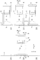
- FIGS. 1 to 8 The following will describe a first embodiment of a stacker crane control system with reference to the drawings ( FIGS. 1 to 8 ). The description is given taking an example where the stacker crane control system according to the present disclosure is applied to an article transport facility as exemplified in FIG. 1 . Note that, in the present embodiment, a control system 1 corresponds to the "stacker crane control system".
- a stacker crane 20 that is controlled by the control system 1 (see FIG. 2 ) includes a travel carriage 21, masts 22, a lift 24, a lifting apparatus 25, and a transfer apparatus 26.
- the travel carriage 21 travels along a travel route 4.
- the travel operation of the travel carriage 21 is controlled by a later-described travel control unit 16 (see FIG. 2 ).
- the travel control unit 16 controls driving of a travel drive unit (for example, an electric motor such as a servomotor) included in the travel carriage 21 so as to control the travel operation of the travel carriage 21.
- the travel route 4 is formed of a travel rail 7.
- the travel rail 7 is provided on a floor part 5 (see FIG. 3 ).
- the travel carriage 21 includes travel wheels that roll on a travel surface of the travel rail 7, and as a result of the travel wheels being driven to rotate by the travel drive unit, the travel carriage 21 travels along the travel rail 7.
- the stacker crane 20 is shown in a simplified manner, and the travel rail 7 provided on the floor part 5 and a later-described guide rail 8 provided on a ceiling part 6 are omitted.
- the lifting apparatus 25 raises and lowers the lift 24.
- the operation performed by the lifting apparatus 25 to raise and lower the lift 24 is controlled by a later-described lifting control unit 17 (see FIG. 2 ).
- the lifting control unit 17 controls driving of a lifting drive unit (for example, an electric motor such as a servomotor) included in the lifting apparatus 25 so as to control the operation performed by the lifting apparatus 25 to raise and lower the lift 24.
- the lifting apparatus 25 raises or lowers the lift 24 by, for example, using driving by the lifting drive unit to rotate a wind-up drum on which a wire connected to the lift 24 is wound, so that the wire is wound up or unwound.
- the transfer apparatus 26 is supported by the lift 24. As shown in FIGS. 1 and 3 , the transfer apparatus 26 includes a holding unit 27 for holding an article 2, and performs a transfer operation of transferring the article 2 between the holding unit 27 and a transfer destination 3.
- the transfer apparatus 26 When the transfer apparatus 26 is located at a position that corresponds to a transfer destination 3 (specifically, a position at which the transfer apparatus 26 faces the transfer destination 3 in the route width direction W) according to the travel operation of the travel carriage 21 and the operation of raising and lowering the lift 24, the transfer apparatus 26 performs the transfer operation.
- the holding unit 27 supports the article 2 (specifically, a central portion of the article 2 in the route longitudinal direction L) from below to hold the article 2.
- the article 2 is placed on and supported by the holding unit 27.
- the operation performed by the transfer apparatus 26 to transfer the article 2 is controlled by a later-described transfer control unit 18 (see FIG. 2 ).
- the transfer control unit 18 controls driving of a transfer drive unit (for example, an electric motor such as a servomotor) included in the transfer apparatus 26 so as to control the transfer operation of the transfer apparatus 26.
- a transfer drive unit for example, an electric motor such as a servomotor
- the transfer apparatus 26 is configured to advance and retract the holding unit 27 in the route width direction W(advancing movement away from the lift 24, and retracting movement toward the lift 24).
- the transfer operation of the transfer apparatus 26 is the operation of advancing and retracting the holding unit 27, and through cooperation between the transfer apparatus 26 and the lifting apparatus 25 (specifically, by performing the operation of raising and lowering the lift 24 in accordance with the transfer operation of the transfer apparatus 26), the article 2 is transferred between the holding unit 27 and the transfer destination 3.
- the transfer apparatus 26 when transferring the article 2 from the transfer destination 3 to the holding unit 27, the transfer apparatus 26 performs the transfer operation and the lifting apparatus 25 performs the operation of raising and lowering the lift 24 such that the holding unit 27 not holding any article 2 is advanced from the retracted position to the advanced position, then the lift 24 is raised, and then the holding unit 27 is retracted from the advanced position to the retracted position. With this, the article 2 is scooped by the holding unit 27, and thus the article 2 is transferred from the transfer destination 3 to the holding unit 27.
- an article transport facility 100 includes at least one storage rack 30.
- the storage rack 30 is arranged in an orientation such that its rack width direction matches the route longitudinal direction L and its rack depth direction matches the route width direction W.
- the travel route 4 is provided on the front side of the storage rack 30 (on the side on which the article 2 is loaded to and unloaded from the storage rack 30).
- the storage rack 30 includes a plurality of storage spaces 31 for storing articles 2.
- the plurality of storage spaces 31 are arranged in multiple rows in the vertical direction V and multiple columns in the route longitudinal direction L.
- each article 2 is stored in a storage space 31 with its side portions in the route longitudinal direction L supported from below.
- FIG. 1 each article 2 is stored in a storage space 31 with its side portions in the route longitudinal direction L supported from below.
- the storage racks 30 are provided on both sides of the travel route 4 in the route width direction W.
- the storage spaces 31 are included in the transfer destination 3.
- the storage spaces 31 serve as transfer destinations 3 set at a plurality of positions determined in the route longitudinal direction L and the vertical direction V.
- the operation control unit 15 includes the travel control unit 16, the lifting control unit 17, and the transfer control unit 18.
- the travel control unit 16 controls the travel operation of the travel carriage 21, the lifting control unit 17 controls the operation performed by the lifting apparatus 25 to raise and lower the lift 24, and the transfer control unit 18 controls the transfer operation of the transfer apparatus 26.
- the transfer control unit 18 controls the transfer operation of the transfer apparatus 26 and the lifting control unit 17 controlling the operation performed by the lifting apparatus 25 to raise and lower the lift 24, the article 2 is transferred between the holding unit 27 and the transfer destination 3.
- the travel control unit 16 controls the travel operation of the travel carriage 21 such that the transfer apparatus 26 is located at a position that corresponds to the support unit 40 (specifically, a position at which the transfer apparatus 26 faces the support unit 40 in the route width direction W), and the lifting control unit 17 controls the lifting apparatus 25 to raise and lower the lift 24.
- the transfer control unit 18 controls the transfer operation of the transfer apparatus 26 such that the article 2 is transferred from the support unit 40 to the holding unit 27.
- the travel carriage 21 is controlled so as to be stopped at reference stop positions S (see FIG. 6 ) that are preset at a plurality of locations in the route longitudinal direction L.
- a reference stop position S is set for each transfer destination 3.
- Each reference stop position S is set such that, when the travel carriage 21 is stopped at the reference stop position S, the lift 24 can be located at a position that corresponds to a transfer destination 3 (the transfer destination 3 set for the reference stop position S).
- a common reference stop position S may be set at a plurality of transfer destinations 3 located at the same level in the route longitudinal direction L. For example, also when there is a small position shift in the route longitudinal direction L between a plurality of storage spaces 31 that belong to the same column, a common reference stop position S may be set for the plurality of storage spaces 31 that belong to the same column.
- the masts 22 sway with their portions connected to the travel carriage 21 (i.e., lower ends of the masts 22) serving as fulcrums for a while after the travel carriage 21 is stopped, due to inertia that occurs when the travel carriage 21 decelerates.
- the lift 24 and the transfer apparatus 26 supported by the lift 24 sway in the route longitudinal direction L. Note that, in FIG.
- the stacker crane 20 in a static state in which the swaying of the masts 22 is stopped and the masts 22 are standing still is indicated by solid lines
- the masts 22 in a state in which the masts 22 are bent to one side (to the right in the drawing) in the route longitudinal direction L with respect to the static state are indicated by dotted lines.
- the masts 22 change to the static state while bending to both sides in the route longitudinal direction L with respect to the static state.
- the transfer operation can be started as soon as possible when the swaying amount is in a range in which no failure will occur in the transfer operation of the transfer apparatus 26.
- the control system 1 by configuring the control system 1 in the following manner, it is possible to start the transfer operation at an appropriate time based on the actual swaying amount of the stacker crane 20 (it is possible to start the transfer operation as soon as possible when the swaying amount is in a range in which no failure will occur in the transfer operation of the transfer apparatus 26), while suppressing an increase in the installation cost of the stacker crane 20.
- the control system 1 includes the sway detection unit 10, the lifting height acquiring unit 14, and the above-described transfer control unit 18 for controlling the transfer apparatus 26.
- the control system 1 further includes the storage unit 19.
- the sway detection unit 10 includes a position detection sensor 11 and a stop position acquiring unit 12.
- the stop position acquiring unit 12 includes a stop-position detection sensor 13.
- the sway detection unit 10 detects a reference swaying amount X1 (see FIGS. 4 and 5 ), which is a swaying amount X of the masts 22 at a detection height H1.
- the detection height H1 is set to at least the height of a lowermost part 26a of the transfer apparatus 26 when the lift 24 is located at the upper limit E1 of the lifting range E.
- the detection height H1 is set to the height of the upper ends (uppermost parts) of the masts 22.
- the swaying amount X is the amount of swaying in the route longitudinal direction L, although the swaying amount X may include, in addition to the swaying amount in the route longitudinal direction L, the swaying amount in the vertical direction V.
- the sway detection unit 10 includes the position detection sensor 11 that dynamically detects the positions of the masts 22 at the detection height H1 in the route longitudinal direction L.
- the position detection sensor 11 is an optical distance detection sensor. The position detection sensor 11 projects detection light D toward a first reflective plate 51, and receives light reflected from the first reflective plate 51, thereby detecting the distance between the position detection sensor 11 and the first reflective plate 51. Based on the distance between the position detection sensor 11 and the first reflective plate 51, the positions of the masts 22 at the detection height H1 in the route longitudinal direction L are derived.
- Either the position detection sensor 11 or the first reflective plate 51 (in the example shown in FIG. 3 , the first reflective plate 51) is fixed to a portion whose position in the route longitudinal direction L does not change, such as the ceiling part 6.
- the remaining one of the position detection sensor 11 and the first reflective plate 51 (in the example shown in FIG. 3 , the position detection sensor 11) is fixed to a fixation target portion of the stacker crane 20.
- the fixation target portion is a portion that sways with the same swaying amount as the swaying amount X of the portion of the mast 22 (in the example of FIG. 4 , the upper end of the mast 22) that is located at the detection height H1.
- the position detection sensor 11 is fixed to the connection part 23 serving as the fixation target portion.
- the position detection sensor 11 may be a sensor (e.g., a rotary encoder) other than an optical distance detection sensor.
- the masts 22 vibrates around a reference position A, which is a position in the static state, and the vibration attenuates.
- the sway detection unit 10 detects a difference between the reference position A and a detection result of the position detection sensor 11, as the reference swaying amount X1. The method for deriving the reference position A will be described later.
- the lifting height acquiring unit 14 acquires lifting height information that indicates a lifting height H2.
- the lifting height H2 is a height (position in the vertical direction V) of the lift 24 at each point in time, as shown in FIGS. 3 and 4 .
- the lifting height H2 varies between the upper limit E1 and the lower limit E2 of the lifting range E of the lift 24.
- the lifting height acquiring unit 14 includes a height detection sensor 28 that detects the height of the lift 24, and acquires a detection result of the height detection sensor 28 as lifting height information.
- a sensor that is used when the lifting control unit 17 controls the operation of raising and lowering the lift 24 may also be used as the height detection sensor 28, or another sensor may be used as the height detection sensor 28.
- the transfer control unit 18 converts the reference swaying amount X1 detected by the sway detection unit 10 into a lifting height swaying amount X2 (see FIGS. 4 and 5 ), which is a swaying amount X of the masts 22 at the lifting height H2 that is indicated by the lifting height information.
- the lifting height swaying amount X2 corresponds to the swaying amount of the lift 24. That is to say, the transfer control unit 18 converts the swaying amount X of the masts 22 at the detection height H1 into the swaying amount of the lift 24.
- the conversion from the reference swaying amount X1 into the lifting height swaying amount X2 can be made based on, for example, a vibration model that approximates the displacement using a cubic function.
- the transfer control unit 18 can obtain the lifting height swaying amount X2 from the reference swaying amount X1 based on the following expression (1).
- X 2 X 1 H 2 / H 1 3
- the conversion from the reference swaying amount X1 into the lifting height swaying amount X2 can also be made based on, for example, a vibration model that approximates the displacement using a linear function.
- the transfer control unit 18 can obtain the lifting height swaying amount X2 from the reference swaying amount X1 based on the following expression (2).
- X 2 X 1 H 2 / H 1
- the detection height H1 and the lifting height H2 (height of the lift 24) in these expressions refer to heights from a common reference height, which can be the height of the connection part that connects the masts 22 and the travel carriage 21 (i.e., lower ends of the masts 22).
- the transfer control unit 18 performs the above-described conversion using an amplitude of swaying of the masts 22 at the detection height H1 (amplitude with the reference position A used as a reference) as the reference swaying amount X1. Therefore, the lifting height swaying amount X2 derived by the transfer control unit 18 indicates the amplitude (crest value) of swaying of the masts 22 at the lifting height H2. Accordingly, in the expressions (1) and (2), the reference swaying amount X1 is an amplitude of swaying of the masts 22 at the detection height H1, and the lifting height swaying amount X2 is an amplitude of swaying of the masts 22 at the lifting height H2.
- the sway detection unit 10 acquires the reference swaying amount X1 repeatedly, and detects an amplitude of the swaying of the masts 22 at the detection height H1 based on time-series data of the reference swaying amount X1.
- the sway detection unit 10 subjects the time-series data of the reference swaying amount X1 to differential processing or the like to detect a peak of the swaying of the masts 22 (peak in vibration waveform), and detects the (absolute) value of the reference swaying amount X1 at the peak as the amplitude of the swaying of the masts 22 at the detection height H1.
- a peak of swaying of the masts 22 appears at a period of half of the natural period of the swaying of the masts 22, and in the example shown in FIG. 5 , peaks of the swaying of the masts 22 appear at time T1, time T2, time T3, time T4, and time T5.
- the transfer control unit 18 converts the amplitude of the swaying of the masts 22 at the detection height H1 that was detected by the sway detection unit 10 in this way into the amplitude of the swaying of the masts 22 at the lifting height H2.
- the transfer control unit 18 determines that the lifting height swaying amount X2 is stably smaller than or equal to the predetermined determination threshold ⁇ X, and starts the transfer operation of the transfer apparatus 26.
- the lifting height swaying amount X2 is smaller than or equal to the predetermined determination threshold ⁇ X for at least a quarter of the above-described natural period, it is determined that the lifting height swaying amount X2 is stably smaller than or equal to the predetermined determination threshold ⁇ X.
- the lifting height swaying amount X2 is determined as being stably smaller than or equal to the predetermined determination threshold ⁇ X.
- the transfer control unit 18 regards the lifting height swaying amount X2 as the swaying amount of the transfer apparatus 26 supported by the lift 24, and determines whether or not to start the transfer operation of the transfer apparatus 26.
- the above-described determination threshold ⁇ X is preferably set to a value as large as possible within a range in which no failure will occur in the transfer operation of the transfer apparatus 26.
- the determination threshold ⁇ X is preferably set taking into consideration the connection relationship or positional relationship between the lift 24 and the transfer apparatus 26 (taking into consideration that, for example, sway may be amplified at the connection part that connects the lift 24 and the transfer apparatus 26).
- the sway detection unit 10 detects a difference between the reference position A and a detection result of the position detection sensor 11, as the reference swaying amount X1.
- the following will describe the method for deriving the reference position A that is performed in the control system 1 of the present embodiment.
- the travel carriage 21 is controlled so as to be stopped at the reference stop positions S (see FIG. 6 ) that are preset at a plurality of locations in the route longitudinal direction L.
- the control system 1 includes the storage unit 19 (see FIG. 2 ) in which information regarding a mast reference position A0 measured when the travel carriage 21 is stopped at each of a plurality of reference stop positions S is stored, the mast reference position A0 being a position of the masts 22 at the detection height H1 in a state in which the travel carriage 21 is stopped at the reference stop position S, and the masts 22 are standing still (are in the static state).
- FIG. 6 shows the masts 22 and the mast reference position A0 in the static state at three reference stop positions S, namely, a first stop position S1, a second stop position S2, and a third stop position S3.
- the stop position acquiring unit 12 includes the stop-position detection sensor 13 that detects the actual stop position R, as shown in FIG. 2 .
- a sensor that is used when the travel control unit 16 controls the travel operation of the travel carriage 21 may also be used as the stop-position detection sensor 13, or another sensor may be used as the stop-position detection sensor 13.
- the sway detection unit 10 obtains a corrected mast reference position A1 based on a detection result of the actual stop position R obtained by the stop-position detection sensor 13. Specifically, by correcting the mast reference position A0 based on a difference between the actual stop position R and the reference stop position S that corresponds to the actual stop position R, the sway detection unit 10 obtains the corrected mast reference position A1. In the example shown in FIG.
- control system 1 The technical features of the control system 1 disclosed in the present specification are applicable to the method for controlling the stacker crane 20, and the method for controlling the stacker crane 20 is also disclosed in the present specification.
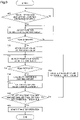
- the control method includes processing (steps) shown in FIGS. 8 and 9 .
- the sway detection unit 10 detects the positions of the masts 22 at the detection height H1 in the route longitudinal direction L (step #02). The detection of the positions of the masts 22 in step #02 is repeated until a peak of swaying of the masts 22 is detected (No in step #03).
- the sway detection unit 10 calculates the reference swaying amount X1 (specifically, the amplitude of the swaying of the masts 22 at the detection height H1) (step #04). In the present embodiment, the sway detection unit 10 derives a difference between the reference position A (mast reference position A0 or corrected mast reference position A1) and a detection result of the position detection sensor 11, as the reference swaying amount X1.
- the transfer control unit 18 calculates the lifting height swaying amount X2 (the amplitude of swaying of the masts 22 at the lifting height H2) (step #05).
- the transfer control unit 18 converts the reference swaying amount X1 calculated in step #04 into the lifting height swaying amount X2, thereby deriving the lifting height swaying amount X2.
- the processing from steps #02 to #05 is repeatedly executed until the lifting height swaying amount X2 calculated in step #05 is smaller than or equal to the determination threshold ⁇ X (No in step #06).
- the transfer control unit 18 starts the transfer operation of the transfer apparatus 26 (step #07).
- the sway detection unit 10 detects a difference between the reference position A and a detection result of the position detection sensor 11, as the reference swaying amount X1.
- the sway detection unit 10 detects a detection result of the position detection sensor 11 as a reference swaying amount X1, and detects the amplitude of swaying of the masts 22 at the detection height H1 without using the reference position A. Therefore, in the present embodiment, there is no need for the sway detection unit 10 to include the stop position acquiring unit 12 nor store information regarding the mast reference position A0 in the storage unit 19.
- the sway detection unit 10 detects the value of half of a difference (i.e., peak-to-peak value) between the currently acquired crest value and the previously acquired crest value, as the amplitude of the dynamic change in the positions of the masts 22 at the detection height H1 (i.e., as the reference swaying amount X1).
- the value of half of a difference between the detection result of the position detection sensor 11 at the time T2 and the detection result of the position detection sensor 11 at the time T1 is detected as the reference swaying amount X1.
- the sway detection unit 10 detects the positions of the masts 22 at the detection height H1 in the route longitudinal direction L (step #11). The detection of the positions of the masts 22 in step #11 is repeated until a peak of swaying of the masts 22 is detected (No in step #12).
- the sway detection unit 10 acquires the detection result of the position detection sensor 11 at this peak as a crest value, and stores this crest value as the previous value (step #13).
- the sway detection unit 10 acquires a detection result of the position detection sensor 11 at the currently detected peak as a crest value, and derives the value of half of a difference between the currently acquired crest value and the previously acquired crest value (crest value stored as the previous value), as the reference swaying amount X1.
- step #20 The processing from steps #14 to #17, and #19 is repeatedly executed until the lifting height swaying amount X2 calculated in step #17 is smaller than or equal to the determination threshold ⁇ X (No in step #18).
- the transfer control unit 18 starts the transfer operation of the transfer apparatus 26 (step #20).
- the first embodiment has described a configuration in which information regarding the mast reference position A0 measured when the travel carriage 21 is stopped at each of the plurality of reference stop positions S is stored in the storage unit 19, as an example.
- the present disclosure is not limited to such a configuration.
- the mast reference position A0 may be set for a plurality of reference stop positions S, as long as no failure will occur in the transfer operation of the transfer apparatus 26 even if the positional relationship between the reference stop position S and the mast reference position A0 in the route longitudinal direction L is regarded as constant.
- the first embodiment has described a configuration in which, assuming that the mast reference position A0 or the corrected mast reference position A1 is the reference position A (position of the mast 22 in the static state), the sway detection unit 10 detects a difference between the reference position A and a detection result of the position detection sensor 11, as the reference swaying amount X1, as an example.
- the present disclosure is not limited to such a configuration.
- a configuration is also possible in which the sway detection unit 10 detects a difference between the reference position A set according to the actual stop position R and a detection result of the position detection sensor 11, as the reference swaying amount X1, as long as no failure will occur in the transfer operation of the transfer apparatus 26 even if the positional relationship between the actual stop position R and the reference position A is regarded as constant.
- the transfer apparatus 26 is configured to advance and retract the holding unit 27 in the route width direction W, and as a result of the advancement and retraction of the holding unit 27 (specifically, as well as raising and lowering of the lift 24), the article 2 is transferred between the holding unit 27 and the transfer destination 3, as an example.
- the present disclosure is not limited to such a configuration.
- a configuration is also possible in which, for example, the transfer apparatus 26 advances and retracts a pair of forward/rearward moving members (for example, a pair of clamp units, or a pair of arms equipped with a hook) in the route width direction W, the pairs of forward/rearward moving members being arranged on both sides of the article 2 in the route longitudinal direction L, and as a result of the transfer operation of the transfer apparatus 26 (specifically, operation of advancing and retracting the pair of forward/rearward moving members), the article 2 is transferred between the holding unit 27 and the transfer destination 3.
- a pair of forward/rearward moving members for example, a pair of clamp units, or a pair of arms equipped with a hook
- a configuration is also possible in which a conveyor (such as a belt conveyor) for conveying the article 2 in the route width direction W is provided on the holding unit 27 or the above-described forward/rearward moving members, and as a result of the conveying operation of the conveyor as well as the operation of advancing and retracting the pair of forward/rearward moving members, the article 2 is transferred between the holding unit 27 and the transfer destination 3.
- a conveyor such as a belt conveyor
- a stacker crane control system for controlling a stacker crane including: a travel carriage that travels along a travel route; a mast supported on the travel carriage in an orientation along a vertical direction; a lift that moves up and down within a predetermined lifting range along the mast; a lifting apparatus that raises and lowers the lift; and a transfer apparatus supported by the lift and including a holding unit for holding an article, the stacker crane being configured to perform a transfer operation of transferring the article between the holding unit and a transfer destination, the stacker crane control system including: a sway detection unit configured to detect a reference swaying amount that is a swaying amount of the mast at a detection height, the detection height being set greater than or equal to the height of a lowermost part of the transfer apparatus when the lift is located at an upper limit of the lifting range; a lifting height acquiring unit configured to acquire lifting height information that indicates a lifting height, which is the height of the lift, at a plurality of points in time; and a transfer control unit configured to control the transfer apparatus
- a lifting height swaying amount that is a swaying amount of the mast at the actual lifting height, based on an actual swaying amount of the mast that is detected by the sway detection unit, and an actual lifting height of the lift at each point in time that is acquired by the lifting height acquiring unit. Then, if the lifting height swaying amount is stably smaller than or equal to a predetermined determination threshold, the transfer operation of the transfer apparatus is started. Since the transfer operation is started in this way based on a detection result of the actual swaying amount of the mast, the transfer operation of the transfer apparatus can be started at an appropriate time according to the actual swaying amount of the mast that varies depending on various operation conditions.
- the travel carriage is controlled so as to be stopped at reference stop positions that are preset at a plurality of locations along the travel route
- the stacker crane control system further includes a storage unit in which information regarding a mast reference position measured when the travel carriage is stopped at each of the plurality of reference stop positions is stored, the mast reference position being a position of the mast at the detection height when the travel carriage is stopped at the reference stop position and the mast is standing still
- the sway detection unit includes a position detection sensor configured to dynamically detect the position of the mast at the detection height in a direction along the travel route, and a stop position acquiring unit configured to acquire stop position information that indicates at which of the plurality of reference stop positions the travel carriage is stopped, and the sway detection unit acquires from the storage unit the mast reference position associated with the reference stop position indicated by the stop position information, and detects, as the reference swaying amount, a difference between the mast reference position and a result of the detection by the position detection sensor, as the reference swaying amount.
- the travel carriage is controlled so as to stop at reference stop positions preset at a plurality of locations in a direction along the travel route, it is possible to appropriately detect the reference swaying amount, which is an actual swaying amount of the mast at the detection height, based on the mast reference position information measured in advance and stored in the storage unit, and a detection result of the position detection sensor.
- the stop position acquiring unit includes a stop-position detection sensor configured to detect an actual stop position, which is a position at which the travel carriage is actually stopped, and the sway detection unit determines a corrected mast reference position by correcting the mast reference position based on a difference between the actual stop position and the reference stop position that corresponds to the actual stop position, and detects, as the reference swaying amount, a difference between the corrected mast reference position and the detection result of the detection by the position detection sensor.
- the present configuration taking into consideration an error between the actual stop position, which is a position at which the travel carriage is actually stopped, and the reference stop position, it is possible to correct the reference stop position, which serves as a reference for use in detecting the reference swaying amount. Therefore, according to the present configuration, it is possible to improve the accuracy in detecting the reference swaying amount.
- the sway detection unit includes a position detection sensor configured to dynamically detect the position of the mast at the detection height in a direction along the travel route, and the sway detection unit detects, as the reference swaying amount an amplitude of a dynamic change in the position of the mast at the detection height which dynamic change is indicated by a result of the detection by the position detection sensor.
- the present configuration it is possible to appropriately detect the reference swaying amount, which is an actual swaying amount of the mast at the detection height, based on an amplitude of a dynamic change in the position of the mast at the detection height indicated by the detection result of the position detection sensor. Therefore, according to the present configuration, there is no need to store information regarding the mast reference position in the storage unit, for example, and it is possible to appropriately detect the reference swaying amount with a relatively simple configuration. Also, according to the present configuration, even if the stop position of the travel carriage is not limited to a preset position, it is possible to appropriately detect the reference swaying amount.
Landscapes
- Engineering & Computer Science (AREA)
- Transportation (AREA)
- Structural Engineering (AREA)
- Mechanical Engineering (AREA)
- Civil Engineering (AREA)
- Life Sciences & Earth Sciences (AREA)
- Geology (AREA)
- Chemical & Material Sciences (AREA)
- Combustion & Propulsion (AREA)
- Warehouses Or Storage Devices (AREA)
Applications Claiming Priority (1)
| Application Number | Priority Date | Filing Date | Title |
|---|---|---|---|
| JP2021007749A JP7415963B2 (ja) | 2021-01-21 | 2021-01-21 | スタッカクレーン制御システム |
Publications (3)
| Publication Number | Publication Date |
|---|---|
| EP4032847A1 true EP4032847A1 (fr) | 2022-07-27 |
| EP4032847C0 EP4032847C0 (fr) | 2024-11-27 |
| EP4032847B1 EP4032847B1 (fr) | 2024-11-27 |
Family
ID=79730472
Family Applications (1)
| Application Number | Title | Priority Date | Filing Date |
|---|---|---|---|
| EP22152255.0A Active EP4032847B1 (fr) | 2021-01-21 | 2022-01-19 | Système de commande de grue empileuse |
Country Status (3)
| Country | Link |
|---|---|
| US (1) | US11926475B2 (fr) |
| EP (1) | EP4032847B1 (fr) |
| JP (1) | JP7415963B2 (fr) |
Families Citing this family (3)
| Publication number | Priority date | Publication date | Assignee | Title |
|---|---|---|---|---|
| EP4219342A4 (fr) * | 2020-10-06 | 2024-10-02 | Murata Machinery, Ltd. | Dispositif de stockage |
| JP7380640B2 (ja) * | 2021-04-26 | 2023-11-15 | 株式会社ダイフク | 物品搬送装置 |
| JP7819661B2 (ja) * | 2023-03-14 | 2026-02-25 | 株式会社ダイフク | スタッカクレーン |
Citations (5)
| Publication number | Priority date | Publication date | Assignee | Title |
|---|---|---|---|---|
| JPH0422801A (ja) | 1990-05-18 | 1992-01-27 | Toshiba Ceramics Co Ltd | 底付きチューブの底厚測定装置 |
| JPH0422801B2 (fr) | 1984-09-21 | 1992-04-20 | Hitachi Ltd | |
| US20050036858A1 (en) * | 2003-07-11 | 2005-02-17 | Daifuku Co., Ltd. | Transporting apparatus |
| US20070059132A1 (en) * | 2005-09-09 | 2007-03-15 | Daifuku Co., Ltd. | Article transport apparatus for an article storage system, and a method of operating the apparatus |
| CN111747344A (zh) * | 2020-06-01 | 2020-10-09 | 苏州穗柯智能科技有限公司 | 一种防晃堆垛机 |
Family Cites Families (7)
| Publication number | Priority date | Publication date | Assignee | Title |
|---|---|---|---|---|
| US1627830A (en) * | 1927-05-10 | Valve construction for automatic hot-water heaters | ||
| JPS6160507A (ja) * | 1984-08-29 | 1986-03-28 | Hitachi Ltd | スタツカ−クレ−ン制御方法 |
| SE0402030L (sv) * | 2004-08-16 | 2006-02-17 | Moving Ab | System och förfarande för lagerhantering |
| JP4228010B2 (ja) | 2006-09-29 | 2009-02-25 | Necエンジニアリング株式会社 | テレビ会議装置 |
| JP5382407B2 (ja) * | 2008-07-14 | 2014-01-08 | 株式会社ダイフク | スタッカークレーンにおける異常検出装置 |
| US9321591B2 (en) * | 2009-04-10 | 2016-04-26 | Symbotic, LLC | Autonomous transports for storage and retrieval systems |
| JP6523296B2 (ja) * | 2013-09-13 | 2019-05-29 | シムボティック エルエルシー | 自動保管および取出システム |
-
2021
- 2021-01-21 JP JP2021007749A patent/JP7415963B2/ja active Active
-
2022
- 2022-01-19 EP EP22152255.0A patent/EP4032847B1/fr active Active
- 2022-01-20 US US17/579,954 patent/US11926475B2/en active Active
Patent Citations (5)
| Publication number | Priority date | Publication date | Assignee | Title |
|---|---|---|---|---|
| JPH0422801B2 (fr) | 1984-09-21 | 1992-04-20 | Hitachi Ltd | |
| JPH0422801A (ja) | 1990-05-18 | 1992-01-27 | Toshiba Ceramics Co Ltd | 底付きチューブの底厚測定装置 |
| US20050036858A1 (en) * | 2003-07-11 | 2005-02-17 | Daifuku Co., Ltd. | Transporting apparatus |
| US20070059132A1 (en) * | 2005-09-09 | 2007-03-15 | Daifuku Co., Ltd. | Article transport apparatus for an article storage system, and a method of operating the apparatus |
| CN111747344A (zh) * | 2020-06-01 | 2020-10-09 | 苏州穗柯智能科技有限公司 | 一种防晃堆垛机 |
Also Published As
| Publication number | Publication date |
|---|---|
| JP2022112100A (ja) | 2022-08-02 |
| US11926475B2 (en) | 2024-03-12 |
| EP4032847C0 (fr) | 2024-11-27 |
| EP4032847B1 (fr) | 2024-11-27 |
| JP7415963B2 (ja) | 2024-01-17 |
| US20220227578A1 (en) | 2022-07-21 |
Similar Documents
| Publication | Publication Date | Title |
|---|---|---|
| EP4032847A1 (fr) | Système de commande de grue empileuse | |
| KR101107137B1 (ko) | 이송 시스템 | |
| CN107428463B (zh) | 负载收纳装置 | |
| US20180111757A1 (en) | Article Transport Facility | |
| JP2007070106A (ja) | 物品収納設備における物品搬送装置 | |
| JP5590411B2 (ja) | スタッカークレーン | |
| JP2008201491A (ja) | 自動倉庫の制御装置 | |
| KR101391222B1 (ko) | 이동체와 그 제어 방법 | |
| JP2008189399A (ja) | スタッカークレーン | |
| JP6627677B2 (ja) | 物品収納設備 | |
| JP4419782B2 (ja) | スタッカクレーン | |
| JP4142700B2 (ja) | 荷すくい装置 | |
| JP5636732B2 (ja) | 自動倉庫 | |
| JP6879022B2 (ja) | 自動倉庫システム | |
| JP5332223B2 (ja) | 自動倉庫及び自動倉庫の荷搬送方法 | |
| JP4973927B2 (ja) | 物品搬送装置 | |
| JP2541431B2 (ja) | スタッカクレ―ン | |
| JP3465778B2 (ja) | 物品保管設備 | |
| JP6673305B2 (ja) | 自動倉庫システム | |
| JP5278744B2 (ja) | 物品収納設備 | |
| CN112919324A (zh) | 起重机运送货物的堆放方法、装置、介质及电子设备 | |
| US20250033893A1 (en) | Article Transferrer | |
| JP4282397B2 (ja) | クランプ装置の昇降制御装置 | |
| JP2006341960A (ja) | 物品収納設備 | |
| JP2007326688A (ja) | スタッカクレーン |
Legal Events
| Date | Code | Title | Description |
|---|---|---|---|
| PUAI | Public reference made under article 153(3) epc to a published international application that has entered the european phase |
Free format text: ORIGINAL CODE: 0009012 |
|
| STAA | Information on the status of an ep patent application or granted ep patent |
Free format text: STATUS: THE APPLICATION HAS BEEN PUBLISHED |
|
| AK | Designated contracting states |
Kind code of ref document: A1 Designated state(s): AL AT BE BG CH CY CZ DE DK EE ES FI FR GB GR HR HU IE IS IT LI LT LU LV MC MK MT NL NO PL PT RO RS SE SI SK SM TR |
|
| STAA | Information on the status of an ep patent application or granted ep patent |
Free format text: STATUS: REQUEST FOR EXAMINATION WAS MADE |
|
| 17P | Request for examination filed |
Effective date: 20230125 |
|
| RBV | Designated contracting states (corrected) |
Designated state(s): AL AT BE BG CH CY CZ DE DK EE ES FI FR GB GR HR HU IE IS IT LI LT LU LV MC MK MT NL NO PL PT RO RS SE SI SK SM TR |
|
| GRAP | Despatch of communication of intention to grant a patent |
Free format text: ORIGINAL CODE: EPIDOSNIGR1 |
|
| STAA | Information on the status of an ep patent application or granted ep patent |
Free format text: STATUS: GRANT OF PATENT IS INTENDED |
|
| INTG | Intention to grant announced |
Effective date: 20240910 |
|
| GRAS | Grant fee paid |
Free format text: ORIGINAL CODE: EPIDOSNIGR3 |
|
| GRAA | (expected) grant |
Free format text: ORIGINAL CODE: 0009210 |
|
| STAA | Information on the status of an ep patent application or granted ep patent |
Free format text: STATUS: THE PATENT HAS BEEN GRANTED |
|
| AK | Designated contracting states |
Kind code of ref document: B1 Designated state(s): AL AT BE BG CH CY CZ DE DK EE ES FI FR GB GR HR HU IE IS IT LI LT LU LV MC MK MT NL NO PL PT RO RS SE SI SK SM TR |
|
| REG | Reference to a national code |
Ref country code: GB Ref legal event code: FG4D |
|
| REG | Reference to a national code |
Ref country code: CH Ref legal event code: EP |
|
| REG | Reference to a national code |
Ref country code: DE Ref legal event code: R096 Ref document number: 602022008026 Country of ref document: DE |
|
| REG | Reference to a national code |
Ref country code: IE Ref legal event code: FG4D |
|
| U01 | Request for unitary effect filed |
Effective date: 20241218 |
|
| U07 | Unitary effect registered |
Designated state(s): AT BE BG DE DK EE FI FR IT LT LU LV MT NL PT RO SE SI Effective date: 20250110 |
|
| U20 | Renewal fee for the european patent with unitary effect paid |
Year of fee payment: 4 Effective date: 20250114 |
|
| PG25 | Lapsed in a contracting state [announced via postgrant information from national office to epo] |
Ref country code: HR Free format text: LAPSE BECAUSE OF FAILURE TO SUBMIT A TRANSLATION OF THE DESCRIPTION OR TO PAY THE FEE WITHIN THE PRESCRIBED TIME-LIMIT Effective date: 20241127 Ref country code: IS Free format text: LAPSE BECAUSE OF FAILURE TO SUBMIT A TRANSLATION OF THE DESCRIPTION OR TO PAY THE FEE WITHIN THE PRESCRIBED TIME-LIMIT Effective date: 20250327 |
|
| PG25 | Lapsed in a contracting state [announced via postgrant information from national office to epo] |
Ref country code: ES Free format text: LAPSE BECAUSE OF FAILURE TO SUBMIT A TRANSLATION OF THE DESCRIPTION OR TO PAY THE FEE WITHIN THE PRESCRIBED TIME-LIMIT Effective date: 20241127 |
|
| PG25 | Lapsed in a contracting state [announced via postgrant information from national office to epo] |
Ref country code: NO Free format text: LAPSE BECAUSE OF FAILURE TO SUBMIT A TRANSLATION OF THE DESCRIPTION OR TO PAY THE FEE WITHIN THE PRESCRIBED TIME-LIMIT Effective date: 20250227 |
|
| PG25 | Lapsed in a contracting state [announced via postgrant information from national office to epo] |
Ref country code: GR Free format text: LAPSE BECAUSE OF FAILURE TO SUBMIT A TRANSLATION OF THE DESCRIPTION OR TO PAY THE FEE WITHIN THE PRESCRIBED TIME-LIMIT Effective date: 20250228 |
|
| PG25 | Lapsed in a contracting state [announced via postgrant information from national office to epo] |
Ref country code: PL Free format text: LAPSE BECAUSE OF FAILURE TO SUBMIT A TRANSLATION OF THE DESCRIPTION OR TO PAY THE FEE WITHIN THE PRESCRIBED TIME-LIMIT Effective date: 20241127 |
|
| PG25 | Lapsed in a contracting state [announced via postgrant information from national office to epo] |
Ref country code: RS Free format text: LAPSE BECAUSE OF FAILURE TO SUBMIT A TRANSLATION OF THE DESCRIPTION OR TO PAY THE FEE WITHIN THE PRESCRIBED TIME-LIMIT Effective date: 20250227 |
|
| PG25 | Lapsed in a contracting state [announced via postgrant information from national office to epo] |
Ref country code: SM Free format text: LAPSE BECAUSE OF FAILURE TO SUBMIT A TRANSLATION OF THE DESCRIPTION OR TO PAY THE FEE WITHIN THE PRESCRIBED TIME-LIMIT Effective date: 20241127 |
|
| PG25 | Lapsed in a contracting state [announced via postgrant information from national office to epo] |
Ref country code: SK Free format text: LAPSE BECAUSE OF FAILURE TO SUBMIT A TRANSLATION OF THE DESCRIPTION OR TO PAY THE FEE WITHIN THE PRESCRIBED TIME-LIMIT Effective date: 20241127 |
|
| PG25 | Lapsed in a contracting state [announced via postgrant information from national office to epo] |
Ref country code: CZ Free format text: LAPSE BECAUSE OF FAILURE TO SUBMIT A TRANSLATION OF THE DESCRIPTION OR TO PAY THE FEE WITHIN THE PRESCRIBED TIME-LIMIT Effective date: 20241127 |
|
| U1N | Appointed representative for the unitary patent procedure changed after the registration of the unitary effect |
Representative=s name: GROSSE, FELIX CHRISTOPHER; DE |
|
| REG | Reference to a national code |
Ref country code: CH Ref legal event code: PL |
|
| PG25 | Lapsed in a contracting state [announced via postgrant information from national office to epo] |
Ref country code: MC Free format text: LAPSE BECAUSE OF FAILURE TO SUBMIT A TRANSLATION OF THE DESCRIPTION OR TO PAY THE FEE WITHIN THE PRESCRIBED TIME-LIMIT Effective date: 20241127 |
|
| PLBE | No opposition filed within time limit |
Free format text: ORIGINAL CODE: 0009261 |
|
| STAA | Information on the status of an ep patent application or granted ep patent |
Free format text: STATUS: NO OPPOSITION FILED WITHIN TIME LIMIT |
|
| PG25 | Lapsed in a contracting state [announced via postgrant information from national office to epo] |
Ref country code: CH Free format text: LAPSE BECAUSE OF NON-PAYMENT OF DUE FEES Effective date: 20250131 |
|
| 26N | No opposition filed |
Effective date: 20250828 |
|
| U20 | Renewal fee for the european patent with unitary effect paid |
Year of fee payment: 5 Effective date: 20251205 |
|
| PG25 | Lapsed in a contracting state [announced via postgrant information from national office to epo] |
Ref country code: IE Free format text: LAPSE BECAUSE OF NON-PAYMENT OF DUE FEES Effective date: 20250119 |