EP4033021A1 - Dispositif de serrage de fil, cadre de fil et d'étirage comprenant un tel dispositif de serrage de fil - Google Patents
Dispositif de serrage de fil, cadre de fil et d'étirage comprenant un tel dispositif de serrage de fil Download PDFInfo
- Publication number
- EP4033021A1 EP4033021A1 EP21177451.8A EP21177451A EP4033021A1 EP 4033021 A1 EP4033021 A1 EP 4033021A1 EP 21177451 A EP21177451 A EP 21177451A EP 4033021 A1 EP4033021 A1 EP 4033021A1
- Authority
- EP
- European Patent Office
- Prior art keywords
- clamping
- yarn
- rod
- clamping rod
- volume
- Prior art date
- Legal status (The legal status is an assumption and is not a legal conclusion. Google has not performed a legal analysis and makes no representation as to the accuracy of the status listed.)
- Granted
Links
Images







Classifications
-
- D—TEXTILES; PAPER
- D03—WEAVING
- D03J—AUXILIARY WEAVING APPARATUS; WEAVERS' TOOLS; SHUTTLES
- D03J1/00—Auxiliary apparatus combined with or associated with looms
- D03J1/16—Apparatus for joining warp ends
- D03J1/18—Apparatus for joining warp ends for joining, e.g. tying, a complete series of fresh warp threads to the used warp threads
-
- D—TEXTILES; PAPER
- D03—WEAVING
- D03J—AUXILIARY WEAVING APPARATUS; WEAVERS' TOOLS; SHUTTLES
- D03J1/00—Auxiliary apparatus combined with or associated with looms
- D03J1/14—Apparatus for threading warp stop-motion droppers, healds, or reeds
Definitions
- the present invention relates to a yarn-clamping device for clamping yarns of a yarn layer.
- the present invention also relates to a yarn frame and to a drawing-in machine comprising such a yarn-clamping device.
- a yarn-clamping device for clamping the different yarns of a warp yarn layer, in particular in a warp preparation process. Clamping the yarns of a yarn layer is needed, for instance, for tying two warp layers together or for drawing-in the warp yarns of a yarn layer into the harness of a loom.
- US-A-5 381 594 discloses a machine for automatically drawing-in warp yarns, where two pairs of yarn-clamping devices are mounted on a single yarn frame longitudinally movable relative to a drawing-in unit. A combination of relative adjustment along a longitudinal direction and along a yarn extension direction is possible between the two lower clamping rails.
- a first embodiment of the clamping device includes a comb introduced in a clamping housing delimited between a fixed wall and a movable wall whose movements may cause jamming of the comb with the clamping rail and blocking of some yarns between the comb and the clamping rail. Thus, even if it is globally satisfactory, such a drawing-in machine is difficult and expensive to implement.
- the clamping device comprises an elastic tube driven by a rotating clamping bar, which are inserted within a clamping rail of a yarn-clamping device, in order to block the yarns within the rail.
- the tube In insertion position of the elastic tube with the yarns between the tube and the clamping rail, the tube is already deformed against the clamping rail which exerts a first clamping action on the yarns that cannot be easily regularly distributed or tensioned in that position.
- the tube and the bar might be ejected from the clamping rail under the high tension in the yarns. In such a case, the yarn clamping process shall be started again from the beginning.
- EP-A-2 662 481 discloses a yarn frame with two spaced clamping rails, each clamping rail being equipped with two rubber profiles and adapted for receiving a clamping rod.
- the two rubber profiles face each other and are parallel to each other.
- the rods introduced in the clamping rails may be ejected from these rails by the reaction effort exerted by the yarns or may have slight movements within the clamping rails in clamping position as the rods only cooperate with the rubber profiles, which might also cause an irregular yarn distribution.
- the two rubber profiles apply a relatively large friction effort on the yarns during rotation of the clamping rod. Depending on the type of yarns, this may cause uneven clamping of the yarns.
- this approach does not allow using an intermediate position for adjusting the yarn position during clamping.
- the present invention aims at solving these problems by providing an optimized yarn-clamping device which allows efficiently clamping the yarns without the risk of ejecting a clamping rod during the yarn clamping process.
- the present invention relates to a yarn-clamping device for clamping yarns of a yarn layer, this device including
- the clamping rod in the clamping position cooperates only with the clamping rail on the other side of the main plane.
- the clamping position of the clamping rod within the clamping volume is thus better controlled. Since the clamping position is reached by rotation of the clamping rod within the clamping volume while the cooperation with the rubber profile occurs on only one side of the main plane, a more regular tension distribution within the yarn layer is obtained.
- the yarn-clamping device of the invention might incorporate one or several of the following features taken in any technically compatible configuration:
- the invention relates to a yarn frame which comprises at least a pair of yarn-clamping devices spaced along a yarn extension direction, whereas at least one of these yarn-clamping devices is as mentioned here-above.
- the yarn frame is configured for clamping yarns of two yarn layers, wherein the yarn frame includes
- the internal surface of the rubber profile of the yarn-clamping device according to the invention is located, within the clamping volume, on the same side of the main plane of the clamping volume as the other yarn-clamping device of the same pair of yarn-clamping devices.
- the invention relates to a drawing-in machine for drawing-in warp yarns into a weaving harness, this drawing-in machine including a drawing-in unit and at least one yarn frame as mentioned here-above.
- the clamping rod when the clamping rod is in the clamping position, the clamping rod partially protrudes through the insertion/extraction opening and out of the clamping rail, the drawing-in unit is movable relative to the yarn frame along the longitudinal axis of the clamping rail, and at least one roller longitudinally secured to the drawing-in unit is in contact with the clamping rod, which protrudes out of the clamping rail, for guiding the relative movement between the drawing-in unit and the yarn frame along the longitudinal axis of the clamping rail.
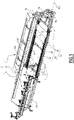
- the drawing-in machine 2 represented on figure 1 includes a movable cart 6 and a fixed structure 4 supporting a drawing-in unit 8, which can be of any known type and is represented by its outer shape.
- the drawing-in machine 2 is designed for holding a first layer L1 and a second layer L2 of warp yarns in position for the drawing-in unit 8 to insert the warp yarns of these layers into a non-represented harness parts of a weaving loom, some of them being mounted on a support member 10 carried by the cart 6.
- a harness is known per se and may include healds, a reed and sometimes drop-wires.
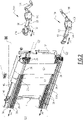
- the two layers L1 and L2 are drawn from one or two non-represented warp beams and held by a yarn tensioning frame 12, also called “drawing-in frame", which includes three posts 14, some cross beams 15 and two beams 16 together forming the main structure of the frame 12.
- the yarn frame 12 is mounted on the fixed structure 4 and can be tilted with respect to this main structure, around an axis parallel to the longitudinal direction of the beams 16.
- Each beam 16 carries two yarn-clamping devices 20 arranged by pairs, respectively provided for holding the yarns of the yarn layer L1 and the yarns of the yarn layer L2 with respect to the yarn frame 12. More precisely, a first yarn-clamping device 20 of each pair of yarn-clamping devices is mounted on the upper beam 16A, whereas a second yarn-clamping device of the same yarn-clamping devices pair is mounted on the lower beam 16B. Thus, the yarn frame 12 includes four yarn-clamping devices 20 in total.
- the beams 16 are hollow, with a globally rectangular cross-section.
- the beams 16 have the same geometry. They can be cut in the same metallic profile.
- the two clamping devices 20 are located next to each other, more precisely one above the other in the configuration of figures 2 , 7 and 8 in which the yarn frame 12 extends essentially in a vertical plane.
- the two yarn-clamping devices 20 of each pair are spaced along a yarn extension direction within the yarn layers L1 and L2, which is vertical on figures 2 , 7 and 8 .
- a first pair of clamping devices 20 is formed by the lower yarn-clamping device 20A1 mounted on the upper beam 16A and by the upper yarn-clamping device 20B1 mounted on the lower beam 16B.
- This first pair of yarn-clamping devices 20 is for clamping the first layer L1.
- This first pair of yarn-clamping devices 20 is formed by the yarn-clamping devices 20A1 and 20B1 respectively mounted on each beam 16 on its side oriented toward the other beam.
- the second pair of yarn-clamping devices 20 is formed by the upper yarn-clamping device 20A2 mounted on the upper beam 16A and by the lower yarn-clamping device 20B2 mounted on the lower beam 16B.
- the second pair of yarn-clamping devices is for clamping the second layer L2 of warp yarns.
- the second pair of yarn-clamping devices is formed by the clamping devices 20A2 and 20B2 respectively mounted on each beam 16 on a side of this beam opposite to the other beam.
- references 20A1, 20A2, 20B1 and 20B2 are used to identify the four yarn-clamping devices. However, in the present example, unless it is specified otherwise, all four yarn-clamping devices are identical and the description of a generic yarn-clamping device identified with reference 20 applies to all yarn-clamping devices.
- Each yarn-clamping device 20 includes a clamping rail 22, a clamping rod 24 and two maintaining devices 26, each maintaining device being assembled, at one respective longitudinal end of the clamping rail 22, by screws 28.
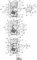
- the clamping rail 22 is made of an aluminum profile, with a constant cross-section along a longitudinal axis X22 of the clamping rail. This cross-section is visible on figure 4 and has globally the shape of a C.
- the clamping rail 22 has an inner cylindrical surface 31 with a circular cross-section of diameter D31 centered on the longitudinal axis X22. This inner cylindrical surface 31 partially delimits a clamping volume V22 within the clamping rail 22. This clamping volume opens on a front face 23 of the clamping rail 22 via an opening O22, at the level of two portions 30a and 30b of an inner cylindrical surface 30, with a cross-section in the form of arcs of a circle also centered on the axis X22, but having a diameter D30 smaller than the diameter D31.
- the clamping rail 22 includes a longitudinal notch 32, which forms a receiving housing for a rubber profile 34, with a globally rectangular cross-section and a side planar surface 36 oriented toward the clamping volume V22.
- the planar surface 36 forms an internal surface of the clamping volume V22 within the clamping rail 22.
- the surface 36 is not a planar surface.
- Y22 defines a transverse axis of the clamping rail 22, perpendicular to axis X22 and which crosses the opening O22 in the middle of this opening. Axes X22 and Y22 are secant. Z22 defines a height or thickness axis of the clamping rail 22, which is perpendicular to axes X22 and Y22. Axes Y22 and Z22 are parallel to the plane of figure 4 and respectively perpendicular and parallel to the front face 23.
- Portions 30a and 30b are at least partially turned toward the bottom of the clamping volume V22 at the opposite of the opening O22 along the transverse axis Y22.
- the front faces 23 of all clamping rails 22 of the yarn frame 12 extend substantially in the same plane, which is vertical in a drawing-in configuration.
- the internal surface 36 of the rubber profile 34 is oriented toward the opening O22, with an inclination angle ⁇ between 10° and 30°, preferably equal to about 20°, with respect to a main plane P22 of the rail 22, containing axes X22 and Y22.
- the main plane P22 crosses the opening O22 in the middle of this opening.
- the inner cylindrical surface 30 extend on both sides of the main plane P22. In other words, portion 30a is situated on one side of the main plane P22 whereas portion 30b is situated on the other side of the main plane P22.
- a single longitudinal notch 32 is provided in the clamping rail 22 so that a single rubber profile 34, or a single line of rubber profiles mounted in continuity along the axis X22, is located next to the clamping volume V22.
- the rubber profile 34 of a yarn-clamping device 20A1 or 20A2 mounted on the upper beam 16A is located, within the corresponding clamping rail 22, downwardly with respect to its clamping volume V22, that is on the side of the clamping rail oriented toward the clamping rail of the other yarn-clamping device 20B1 or 20B2 belonging to the same pair of yarn-clamping devices 20 along axis Z22.
- the rubber profiles 34 of the two upper yarn-clamping devices 20A1 and 20A2 are located below their clamping volumes V22, whereas the rubber profiles 34 of the two lower yarn-clamping devices 20B1 and 20B2 are located above their respective clamping volumes V22.
- the internal surface 36 of the rubber profile 34 is located on a single side of the clamping volume V22, with regard to the main plane P22, this single side being oriented toward the other clamping device 20 of the same pair of clamping devices along axis Z22.
- One or several spacers 38 can be received within the longitudinal notch 32 of each clamping rail 22 in order to adjust the projecting position of the internal surface 36 within the clamping volume V22.
- the clamping rod 24 is made of a metal, such as aluminum or steel, and extends along a longitudinal axis X24, which is parallel to axis X22 at least in mounted configuration of the clamping rod 24 within the clamping volume V22.
- the clamping rod 24 includes a central portion 42 configured to be received within the clamping volume V22, two end portions 44 having a generally square cross-section and two intermediate portions 46.
- Each intermediate portion 46 is located, along the axis X24, between the central portion 42 and one of the end portions 44, i.e. at a longitudinal side of the central portion 42.
- the clamping rod 24 is cylindrical, with a truncated circular cross-section defining, on one part of the periphery of the clamping rod 24, a circular surface 48 centered on the axis X24 with a diameter D1 and, on the remaining part of this, a planar surface 50.
- An external dimension d2, measured perpendicular to the axis X24, between this planar surface 50 and the most remote portion of the circular surface 48, is strictly smaller than the diameter D1.
- the clamping rod 24 has, around axis X24, a non-circular profile in a cross-section taken in a plane perpendicular to the axis X24.
- P24 denotes a main plane of the rod 24, which includes its longitudinal axis X24 and is parallel to the planar surface 50.
- the maximum external dimension of the non-circular profile of the rod 24 extends parallel to the main plane P24 and equals diameter D1.
- This diameter D1 is larger than the maximum external dimension of the rod perpendicular to this main plane P24, that is distance d2.
- Diameter D1 is substantially equal to diameter D30, for example equal to 36 mm.
- the square cross-section of the end portions 44 of the clamping rod 24 is adapted to cooperate with a non-represented tool, such as wrench, in order to exert a torque on the clamping rod 24, around the axis X24.
- the clamping rod 24 includes two planar and parallel surfaces 52 and 54 and two surfaces 56 and 58 in the form of portions of cylinders with a circular basis centered on a longitudinal axis.
- d2' denotes the distance between surfaces 52 and 54, this distance being measured perpendicularly to these surfaces.
- this distance d2' is slightly smaller than the dimension d2.
- D1' denotes the diameter of surfaces 56 and 58.
- this diameter D1' is slightly smaller than the diameter D1.
- planar surface 52 of an intermediate portion 46 extends the planar surface 50 of the central portion 42 toward the adjacent end portion 44, whereas the planar surface 54 extends one of the planar surfaces of the end portion 44 toward the central portion 42.
- Each maintaining device 26 includes a body 60 made of a main body portion 62, a support plate 64 and a cover 66 fastened all together. Parts 62 and 66 are provided with bores 68 for the passage of the screws 28.
- the main body portion 62 is also provided with a threaded hole 70 for the reception of a screw 72 going through a bore 74 of the cover 66 and fixing the cover 66 and the main body portion 62 together.
- the maintaining device 26 is used for limiting a rotation movement of the clamping rod 24 within the clamping volume V22.
- the main body portion 62 defines a housing H26 for the reception of a C-shaped retaining member 76. More precisely, the main body portion 62 has an internal cylindrical surface 80 with a circular cross-section centered on a central axis X60 of the body 60. The main body 62 also has an end wall 82 which delimits axially the housing H26 on the one side, whereas the cover 66 delimits this housing on the other side, along axis X60.
- the end wall 82 and the cover 66 are respectively provided with central apertures 84 and 85 for the passage of the clamping rod 24.
- the two central apertures 84 and 85 have the same geometry.
- the main body 62 is also provided with a through hole 86 which goes from the housing H26 to an external surface 88 of the main body 62.
- This through hole 86 constitutes a housing for a shuttle 90 which is elastically biased by a spring 92 toward the housing H26, in such a way that a rounded end 94 of the shuttle 90, opposite to the spring 92, can protrude within the housing H26.
- a protrusion 93 is provided on the support plate 64 for centering the spring 92.
- the support plate 64 cooperates with the main body portion 62 to support the shuttle 90 within the through hole 86.
- Y60 denotes a transverse axis of the body 60, which is perpendicular to axis X60 and passes through the opening O26.
- the movement of the shuttle 90 occurs along the longitudinal axis A90 of the shuttle, which is parallel to the axis Z22, i.e. transverse to the longitudinal axis X60 and to the axis Y60, in mounted configuration of the maintaining device 26 on the clamping rail 22.
- the movement of the shuttle 90 toward the housing H26 is limited by a shoulder formed by an annular collar 96 of the shuttle 90 which comes into abutment against an inner shoulder 98 formed within the through hole 86, as can be seen by the comparison of the two upper parts of figure 5 .
- the movement of the shuttle 90 away from the housing H26 is limited by the support plate 64, which is immobilized onto the main body portion 62 by two screws 99 going through two orifices 100 provided in the support plate 64 and screwed in two threaded blind holes 101 provided in the main body portion 62.
- the shuttle 90 is provided with a through hole 102 transverse to its longitudinal axis A90.
- the through hole 102 is dimensioned in order to accommodate the ends of two transverse pins 104 housed in oblong slots 106 and 108 respectively provided in the main body portion 62 and in the cover 66.
- the transversal pin visible on the left of figure 6 goes through the slot 108 and a first portion of slot 106 in order to be engaged into the through hole 102 while still protruding out of the cover 66.
- the transversal pin 104 visible on the right of figure 6 goes through a non-visible portion of the slot 106 which connects the through hole 86 to the face of the main body portion 62 perpendicular to the axis X60 and which is not visible on figure 6 .
- This transversal pin 104 also protrudes out of the main body portion 62. With this arrangement, transversal pins 104 allow moving the shuttle 90 within through hole 86, against the elastic action of the spring 92, when necessary.
- the retaining member 76 has an outer cylindrical surface 120 with a circular cross-section centered on a central axis X76 of the retaining member 76.
- the retaining member 76 has two end surfaces 121, 123 perpendicular to the axis X76, which respectively face the cover 66 and the end wall 82, so that the retaining member 76 is secured, in a longitudinal direction parallel to axis X60, within the housing H26.
- the body 60 has an opening O26 formed on a lateral face 122 of the main body portion 62 and on an edge of the cover 66 and which connects the housing H26 to the outside of the body 60.
- W26 denotes the width of the opening O26, which is larger than the distance d2'.
- the openings O22 and O26 extend next to each other along axis X22.
- the axis Y60 is perpendicular to the lateral surface 122.
- Z60 defines another transverse axis of the body 60, which is perpendicular to axes X60 and Y60 and parallel to the lateral surface 122.
- the axis Z60 is parallel to the longitudinal direction of the through hole 86 and to the longitudinal axis A90 of the shuttle 90.
- the width W26 is measured parallel to the axis Z60.
- Axes X60, Y60 and Z60 are secant.
- the outer surface 120 of the retaining element 76 matches with the internal cylindrical surface 80 which defines the housing H26, with a possibility of a movement of limited amplitude of the retaining element 76 within the housing H26 only in the direction of axis Z60.
- the retaining element 76 may move axially along axis Z60 within the housing H26, with a limited amplitude.
- the retaining element 76 is accommodated within the housing H26 without possibility of movement out of the housing H26 in the transverse direction parallel to the axis Y60, thus to the axis Y22, when the maintaining device 26 is mounted at one end of the clamping rail 22.
- the housing H26 forms a guiding housing for guiding the retaining member 76 in rotation around axes X60 and X76 when they are superimposed.
- the retaining element 76 defines a central notch 124, which extends from the end surface 121 to the end surface 123 and between two planar and parallel surfaces 126 and 128 parallel to, and non-secant with, the axis X76.
- the axis X76 passes through the notch 124.
- the retaining element 76 has a bottom 130 and two branches 132 and 134, which respectively define the planar surfaces 126 and 128, on either side of the notch 124.
- the notch 124 opens on the outer cylindrical surface 120 in a direction opposite to the bottom 130.
- the notch 124 is configured for receiving an intermediate portion 46 of the clamping rod 24.
- a yarn-clamping device Upon assembly of a yarn-clamping device, a maintaining device 26 is mounted at each longitudinal end of the clamping rail 22.
- a yarn-clamping device thus comprises two maintaining devices 26, two retaining elements 76 and two shuttles 90.
- Axes X22 and X60 are aligned and superimposed, axes Y22 and Y60 are made parallel and axes Z22 and Z60 are made parallel.
- the yarn layer L1 or L2 is drawn from the warp beam in order to extend along the front face 23 of this clamping rail 22. Between the warp beam and the front face 23, the yarns 200 of each yarn layer L1 or L2 are guided by one of two rollers 138.
- each opening O26 is a passage-opening for the clamping rod 24.
- each retaining member 76 is in a release position, oriented as shown in the upper portion of figure 5 , with its surfaces 126 and 128 parallel to the axis Y60.
- the or each opening O26 extends further away from a plane containing axes X60 and Z60 than the opening O22 extends away from a plane containing axes X22 and Z22.
- the opening O22 corresponding to the clamping volume V22 is located, along the transverse direction Y22 or Y60, between the clamping volume V22 and the opening O26 corresponding to each housing H26.
- the branch 132 of the retaining member 76 extends further away from the axis X76, toward the opening O26, than the volume V22 extends up to the opening O22.
- the planar surface 52 of its intermediate portions 46 starts sliding on the planar surface 126 of the two retaining members 76 before its central portion 42 enters the clamping volume V22, via the opening O22.
- the two planar surfaces 126 form guiding surfaces of the central portion 22 toward the clamping volume V22.
- the clamping rod 24 is in an insertion position where the rod 24 may still pass through the opening O22, in an extraction movement, opposite to introduction movement of the clamping rod represented by arrows A1.
- the planar surface 50 faces the internal surface 36.
- each maintaining device 26 is in a release position represented on top of figure 5 , where it does not block a movement of the corresponding intermediate portion 46 along axis Y60, in the direction of arrow A1 or in the opposite direction.
- the rounded end 94 of the shuttle 90 cooperates with the retaining member 76, by sliding contact with the outer cylindrical surface 120 of the retaining member 76, and does not prevent any rotating movement of the retaining element 76 around its axis X76.
- the maintaining device 26 is in a release configuration.
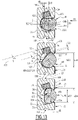
- a clamping direction can be defined as a rotation direction, which brings the clamping rod 24 relative to the clamping rail 22 from the insertion position, represented on top of figures 4 and 5 , successively to the intermediate position, represented in the middle of figures 4 and 5 , and to the clamping position, represented at the bottom of figures 4 and 5 .
- This clamping direction is a rotational direction around the axis X24, in the direction of arrows R2 on figures 4 and 5 .
- the inner cylindrical surface 30 and the circular surface 48 cooperate for guiding the rotation movement of the clamping rod 24 in the clamping volume V22. This creates a regular tensioning of the yarns 200 along the yarn layer width.
- the internal surface 36 projects, at least partially, into a cylindrical volume whose diameter is equal to the maximum dimension of the clamping rod, i.e. equal to diameter D1, and which is delimited in the clamping volume V22 all around the rotation axis X24 of the clamping rod 24.
- This rotation in the clamping direction R2 of the clamping rod 24 induces a corresponding rotation of the retaining member 76 around the same axis with the same angular amplitude, also represented by arrows R2 on figure 5 , since the intermediate portion 46 and the retaining member 76 are coupled together in rotation around the axes X24 and X76, by cooperation of shapes between the surfaces 52 and 126, on the one hand, 54 and 128, on the other hand.
- the cylindrical surface 120 is secured in rotation with the clamping rod around axis X24.
- This position is an intermediate position for the clamping rod 24, where the yarns 200 go through the clamping volume V22 but are not blocked within this clamping volume, insofar as they can slide with regard to the central portion 42.
- the maximum external dimension d24 of the cross-section of the central portion 42 of the clamping rod 24, this dimension being parallel to the axis Z22, is larger than the distance d2 and smaller than the diameter D1.
- d24 is equal to 35 mm.
- W22 denotes the width of the opening O22, which is measured parallel to the axis Z22, that is perpendicularly to the axis Y22.
- W22 is for example equal to 30 mm.
- W22 is between 75% and 90% of the diameter D1.
- W22 is substantially equal to the dimension d2.
- the portions 30a and 30b face the clamping rod 24 in the direction of arrow A1 along the transverse direction Y22.
- the external dimension d24 is strictly larger than the width W22 measured at the same level along the longitudinal axis X22 as external dimension d24.
- a difference d3 d3a+d3b between the maximum dimension d24 and the width W22 is sufficient to create on the clamping rail 22, within the clamping volume V22, a retaining zone by cooperation of shapes between the clamping rod and the portions 30a, 30b for blocking the clamping rod 24 within this clamping volume.
- This retaining zone extends on the whole length of the longitudinal central portion 42 received in the clamping volume V22 and on both sides of the main plane P22, as shown by the two references d3a and d3b on figure 4 , which avoids bending of the clamping rod 24, in particular when this length is more than 3 meters.
- the clamping rod 24 cooperates only with the rubber profile 34 on one side of the main plane P22, with the yarns 200 in-between, whereas the clamping rod 24 cooperates only with the clamping rail 22 on the other side of the main plane P22, with the yarns 200 in-between.
- the circular surface 48 faces the internal surface 36. The portions 30a, 30b and the circular surface 48 cooperate together in a form-fitting manner, with the yarns 200 in-between.
- the clamping rod 24 partially protrudes through the insertion/extraction opening O22 and out of the clamping rail 22.
- the clamping rod 24 protrudes out of the clamping rail 22 only beyond the portion of the front face 23 situated on the same side of the main plane P22 as the internal surface 36, over a non-zero distance d5.
- the clamping rod 24 does not protrude out of the clamping rail 22 beyond the portion of the front face 23 situated on the other side of the main plane P22.
- the second branch 134 of the retaining member 76 is interposed between the clamping rod 24 and the opening O26, so that it prevents the passage of the intermediate portion 46 of the clamping rod 24 out of the notch 124 and also holds the corresponding intermediate portion 46 within the housing H26.
- This position is thus a holding position for the retaining member 76.
- d4 denotes a distance, measured in the holding position of the retaining member 76 parallel to the axis Z60, between the free end 135 of its branch 134, on the one hand, and an edge 63 of the main body portion defining the opening O26 next to the through hole 86.
- This distance d4 is strictly smaller than the width W26, preferably less than 75% of this width.
- d4 is equal to 16 mm and W26 is equal to 30 mm.
- d24' denotes the maximum external dimension of the cross-section of the intermediate portion 46 parallel to the axis Z60 in the intermediate position of the clamping rod 24, that is in the holding position of the retaining member 76.
- This dimension d24' is preferably smaller than, or equal to, the maximum dimension d24.
- This dimension d24' is strictly larger than the distance d4, so that the clamping rod 24 is locked within the housing H26 by the retaining member 76.
- the remaining width, also called "apparent width” of passage through the opening O26 for the intermediate portion 46 is reduced to the distance d4, which is smaller than the dimension d24'. This prevents extraction of the clamping rod 24 from the housing H26.
- the shuttle 90 Due to the rotation of the retaining member 76, the shuttle 90 does not bear anymore against the outer cylindrical surface 120, so that its movement toward the housing H26 is no more limited by the retaining member 76. Thus, the shuttle 90 is pushed by the spring 92 up to a contact between its collar 96 and the shoulder 98, so that its rounded end 94 protrudes within the housing H26 in a blocking position. This occurs automatically, because of the action of the spring 92, during the rotation of the retaining member 76 in the clamping direction of the arrow R2, without an action of an operator.
- the shuttle 90 In this blocking position and for the clamping rod 24 in the intermediate position, the shuttle 90 is in contact with the retaining member 76 in a circumferential direction around axes X24 and X76.
- the shuttle 90 forms an obstacle to the rotation of the retaining member 76 in the direction of arrow R3 on figure 5 , around axis X76.
- the retaining member 76 cannot go back to its release position by a rotation in a direction R3 opposite to the clamping direction R2, since this rotation movement is blocked by the obstacle-forming shuttle 90.
- the shuttle can also be called an obstacle for the retaining member 76.
- the maintaining device 26 is then in a holding configuration.
- the retaining member 76 is coupled, in rotation around axes X24 and X76, with the clamping rod 24 by cooperation of shapes of surfaces 52, 54, 126 and 128, the retaining member 76, blocked by the obstacle formed by the shuttle 90, prevents a rotation of the clamping rod 24 in the direction of arrow R3.
- the retaining member 76 is used as an interface between the obstacle 90 and the portion 46 of the clamping rod 24.
- the clamping rod 24 can move from the intermediate position to the clamping position represented at the bottom of figure 4 , where the yarns 200 are pinched between its central portion 42 and the internal surface 36 of the rubber profile 34.
- the shape and location of the rubber profile 34 is such that, when it is in the clamping position, a joining edge 49 between the surfaces 48 and 50 of the central portion 42 slightly penetrates the rubber profile 34 at the level of the internal surface 36, with the yarns 200 in-between, which ensures a proper clamping of the yarns 200 within the clamping volume V22.
- the clamping rod 24 penetrates the internal surface 36 when the yarns 200 are pressed against the rubber profile 34 by the clamping profile 24, which causes a local deformation of the rubber profile 34.
- clamping rod 24 is made of one piece, surfaces 48 and 50, and edge 49 are made up of metal.
- the obstacle-forming shuttle 90 does not move relative to the body 60 and the retaining member 76 has no transverse movement along the axis Y60.
- the rod In the clamping position of the clamping rod 24, the rod is oriented around the axis X24 in such a way that its diameter D1 equals the maximum external dimension d24 of its central portion 42, this dimension being parallel to axis Z22.
- the ratio d24/W22 is strictly larger than 1, where the dimension d24 and width W22 are measured at the same longitudinal level along the longitudinal axis X22, and the portions 30a and 30b of the inner cylindrical surface 30 together form a retaining zone for holding the clamping rod 24 within the clamping volume V22, as shown at the bottom of figure 4 .
- the retaining member 76 In the clamping position, the retaining member 76 is in a third position, distinct from the holding position, because the clamping rod 24 and the retaining member 76 are coupled and move together in rotation between the intermediate position and the clamping position of the clamping rod 24.
- a tensioning device 140 belongs to the frame 12 and allows adjusting the position of the upper beam 16A along the posts 14, as shown by double arrow A2 on figures 7 and 8 .
- one tensioning device 140 is mounted between each post 14 and the upper beam 16A.
- the direction of the adjusting movement of the upper beam 16A is a direction of approach/distance with respect to the lower beam 16B, this direction being perpendicular to the longitudinal directions of these beams. This direction is parallel to the axes Z22 of the clamping rails of the four yarn-tensioning devices 20.
- Each tensioning device 140 includes a spindle 142 which is actually movable and connected, by a bracket 144, to the upper beam 16A.
- a first spindle can be operated by the operator via a non-represented ratchet wrench and its rotational movement is transmitted to the other spindles, which form driven spindles, by one or several synchronization chains 146.
- the lower beam 16 is mounted on the posts 14 without any possibility of movement.
- the tensioning device 140 it is possible to adjust a distance between the two clamping devices 20 of a pair of clamping devices, parallel to their axes Z22, thus to adjust the tension of the yarns of the first and second layers L1 and L2.
- the yarn frame 12 is mounted on some posts 150 of the fixed structure 4 of the drawing-in machine 2 with possibility of a variable inclination with regard to this fixed structure. This is obtained by a system of articulated levers 152, articulated on the posts 150. Each lever 152 is associated with a gas spring 154. The operator can thus prepare clamping and tensioning of the layers L1 and L2 when the yarn frame 12 is substantially horizontal, that is in a position of the yarn frame 12 where the openings O22 of the clamping rails 22 are oriented upwardly, facing the top in a vertical direction. Before starting the drawing-in process, the yarn frame is tilted back to a vertical drawing-in position represented on figures 2 , 7 and 8 .
- the yarn frame 12 can be stationary with respect to the fixed structure 4.
- the relative movement of the drawing-in unit 8 with respect to the yarn frame 12 may result from the fact that the drawing in-unit is movable during the drawing-in process along a longitudinal axis X12 of the yarn frame 12, whereas the yarn frame 12 remains stationary. Alternatively, the drawing-in unit is stationary and the yarn frame moves during the drawing-in process.
- the lower beam 16 supports two clamping devices 20 and the upper beam 16 supports two other clamping devices, as explained here-above.
- a single clamping device 20 can be mounted on each beam 16.
- the clamping rail 22 of each clamping device 20A2 and 20B2 of the second pair of clamping devices is movable along the corresponding beam that supports it, that is parallel to its longitudinal axis X22.
- the clamping rail 22 is controlled by a dedicated adjusting device 160.
- This adjusting device 160 includes a nut 162 in threaded engagement with a spindle 164 and guided by a rail 165 fastened to the main structure of the yarn frame 12, in particular along axis X22.
- a bevel gear 166 driven by a crank handle 168 drives the rotation of the spindle 164, thus the displacement of the nut 162 along a direction parallel to the axis X22 of the clamping rail, as represented by arrows A3 on the figures.
- adjusting devices 160 are represented separated from the yarn frame 12, and at a bigger scale.
- the upper adjusting device 160 is represented in its configuration of use on the yarn frame 12.
- Each adjusting device 160 also includes a bolt 170 screwed in its nut 162.
- the bolt 170 of the lower adjusting device 160 is not represented on figure 2 .
- Each bolt 170 is configured for being threaded in a threaded hole 172 located next to one end of the clamping rail 22 of a yarn-clamping device 20A2 or 20B2.
- Each longitudinal end of the clamping rail 22 has a cut-out 174 for the reception of a retractable support 176.
- a bolt 170 and a threaded hole 172 allows transferring the translational movement of the nut 162 of an adjusting device 160 along its rail 165 to the clamping rail 22 of the associated yarn-clamping devices 20A2 or 20B2, which translate along its longitudinal axis X22.
- an interface 179 is longitudinally interposed between the body 60 of the maintaining device 26 and the longitudinal end of the clamping rail 22 on the adjusting device longitudinal side.
- This interface 179 is fastened to the body 60 by the screws 28.
- This interface is fastened to the nut 162 by a screw 181 which extends through the nut 162, parallel to the bolt 170, and which is engages in a threaded hole of the interface. Then, since the nut 162 is fixed at the end of the clamping rail 22 and with the interface 179, the adjacent maintaining device 26 is indirectly secured to the clamping rails 22.
- each longitudinal beam 16 is provided with some guiding protrusions 180, which are regularly distributed all along the length of the beam 16.
- a set of two protrusions 180 arranged to be located respectively above and under a clamping rail 22, together form a guiding set 182.
- the guiding sets 182 are distributed along the length of the beams 16.
- the two protrusions 180 of a guiding set 182 are aligned along a direction parallel to the direction of the yarns 200 in a yarn layer L1 or L2, i.e. along a direction parallel to the axis Z22.
- each clamping rail 22 is provided with two longitudinal grooves 184 configured for accommodating each a protrusion 180 and for sliding on this protrusion when the nut 162 moves along the rail 165, if this clamping rail 22 is associated to an adjusting device 160.
- the two longitudinal grooves 184 of a rail have the same geometry, but are offset along the axis Y22.
- the upper yarn-clamping device 20A2 of the second pair of yarn-clamping devices is partially detachably mounted on the main structure of the yarn frame 12, in particular on its upper beam 16.
- the walls of the two longitudinal grooves 184 are regularly interrupted along the clamping rail length, by cut-outs 186.
- the distance between two adjacent cut-outs 186 along the axis X22 is the same as the distance between two adjacent guiding sets 182 along the longitudinal direction of the upper beam 16A.
- the length L186 of a cut-out measured parallel to axis X22 is larger than the length L180 of each protrusion 180 measured parallel to the longitudinal direction of the beam 16A.
- the clamping rail 22 of the yarn-clamping device 20A2 is already fastened by screws 28 with a maintaining device 26 on its longitudinal side opposite to the threaded hole 172 and the adjusting device 160.
- the interface 179 and the maintaining device 26 located on the longitudinal side of the adjusting device 160 are already fastened to the main structure of the yarn frame 12.
- the yarn-clamping devices 20A2 is partially detachably mounted on the longitudinal beam 16 of the yarn frame 12 insofar only one screw connection formed by the bolt 170 and the threaded hole 172 is required to mount the clamping rail 22 already equipped with one maintaining device 26 on the main structure of the yarn frame 12.
- each maintaining device 26 of a yarn-clamping device 20A2 or 20B2 follows the translational movement of the clamping rail.
- these maintaining devices 26 can be stationary with regard to the yarn frame 12 and the intermediate portions 46 of the clamping rod 24 slide within these maintaining devices when the clamping rail 22 moves along its axis X22, between these maintaining devices.
- the detachable yarn-clamping device is the lower yarn-clamping device 20B2 mounted on the lower beam 16B.
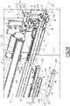
- the length L180 of each protrusion 180 along the longitudinal direction of the upper beam 16A is kept as small as possible. Indeed, as shown on figures 9 and 10 , the yarn separation at the level of the guiding sets 182 induces the creation of zones Zd of disturbance in the yarn distribution along the yarn width of the yarn layer L1. Keeping the length L180 small allows minoring these zones of disturbance.
- all clamping rails 22 of the four yarn-clamping devices 20 are extruded from the same die. They all have the same constant cross-section, in particular with two opposite longitudinal grooves 184.
- some protrusions 180 located between two adjacent clamping rails 22 mounted on the same beam 16 are engaged in a first longitudinal groove 184 of a first clamping rail 22 which belongs to a first pair of yarn-clamping devices 20 and in a second longitudinal groove 184 of the adjacent clamping rail 22 of a yarn-clamping device 20 which belongs to the second pair of yarn-clamping devices 20.
- a clamping method for clamping the yarns 200 of a yarn layer L1 or L2 with a yarn-clamping device 20 is described here-below in connection with a single yarn clamping device 20.
- the yarns 200 are drawn from the warp beam in order to cover the front face 23 of the clamping rail 22 in which the opening O22 is formed. In this configuration, the yarns 200 are located outside the clamping volume V22 of the yarn clamping device 20.
- both maintaining devices 26 are in release configuration.
- the notch 124 opens toward the opening O26.
- the clamping rod 24 can be inserted into the clamping volume V22 and into the housings H26 by a translation parallel to axes Y22 and Y60, in the direction of arrows A1. Because of the direction of this translation, the clamping rod 24 pushes the yarns and deflects them into the clamping volume V22. If, during the insertion movement of the clamping rod 24, the clamping rod 24 extends parallel to the axis X22, the action of the clamping rod 24 on the yarns 200 is the same over the width of yarn layer, parallel to the axis X24. During this translational movement, the planar surface 50 of the clamping rod 24 is oriented toward the rubber profile 34 and the planar surface 54 slides along the planar surface 126, once the intermediate portion 46 of the clamping rod 24 crosses the opening O26.
- the movement of the clamping rod 24 is guided toward the clamping volume V22 by the notch 24 formed in the retaining member 76.
- the planar surfaces 52 and 54 of the intermediate portions 46 of the clamping rod 24 slide along the planar surfaces 126 and 128 of the retaining member 76 and are guided toward the bottom 130 of the notch 124.
- This guiding cooperation between parts 46 and 76 starts before the central portion 42 enters the clamping volume V22 since a distance between the opening O26 and the axis X60, measured along the axis Y60, is larger than a distance between the opening O22 and the axis X22, measured along the axis Y22.
- This movement in the direction of arrows A1 goes on up to the abutment of the surface 58 of the intermediate portion 46 against the bottom 130 of the two notches 124.
- the clamping rod 24 is then in an inserted position within the clamping rail 22. From this position, the rod 24 can still be extracted from the clamping volume V22, if needed.
- the retaining member 76 is in its release position.
- the retaining member 76 is pushed by the rounded end 94 of the shuttle 90 which induces a slight displacement of the retaining member 76 within the housing H26, parallel to the axis Z60, in a direction away from the support plate 64.
- the outer cylindrical surface 120 of the retaining member 76 comes into abutment against the portion of the internal cylindrical surface 80 opposite the through hole 86. This allows guiding the rotation of the retaining member within the housing H26, by cooperation of surfaces 80 and 120.
- Axes X22, X24, X76 and X60 are then superimposed and form a common longitudinal axis X20 of the yarn-clamping device 20.
- Each longitudinal beam 16 extends parallel to the common longitudinal axis X20.
- the clamping rod 24 is then turned in the clamping direction represented by arrows R2 around the common central axis X20 by about 40°. This brings the clamping rod 24 in its intermediate position represented in the middle part of figures 4 and 5 . This also brings the retaining member 76 into its holding position represented in the middle part of figure 5 . During this movement, the outer cylindrical surface 80 of the retaining member 76 slides in contact with the rounded end 94 of the shuttle 90 until the end 133 of its branch 132 is angularly shifted with regard to the obstacle formed by the shuttle 90.
- the intermediate portion 46 of the clamping rod 24 is blocked within the housing H26 by the retaining member because of the difference between the maximum dimension d24' and the remaining width d4 of the opening O26, as explained here-above.
- the yarns exert on the clamping rod 24 an effort which tends to push the clamping rod 24 out of the clamping volume V22, through the openings O22 and O26 and to rotate the clamping rod in a direction opposite to the clamping direction.
- the retaining member 76 the intermediate portions 46 are held within the housings H26, so that the central portion 42 is held within the clamping volume V22 in the intermediate position. In other words, the retaining member 76 opposes to the effort exerted by the yarns 200 on the clamping rod 24.
- the obstacle formed by the shuttle 90 does not prevent further rotation of the retaining member 76 in the clamping direction R2 toward the clamping position. It is thus possible to move the clamping rod 24 from the intermediate position to the clamping position, with the retaining member 76 driven by the clamping rod 24 between these two positions, by cooperation of shapes, as mentioned here above.
- the shuttle 90 is in its blocking position.
- the third position corresponds to a rotation of the retaining member 76 on about 90° around the common axis X20 with respect to the release position.
- the minimal distance between the clamping rod 24 and the internal surface 36 is reduced.
- this minimal distance is such that the yarns 200 are pressed between the clamping rod 24 and the internal surface 36 of the rubber profile 34, which ensures a regular clamping of the yarns 200 along length of the clamping rail 22.
- the yarns 200 cannot move within the clamping volume V22 between the internal surface 36 and the clamping rod 24 if these yarns are subjected to normal efforts of the warp preparation process, of the drawing-in process for example.
- planar surfaces 50, 52, 54 are globally parallel to the axis Z22, Z60 that is perpendicular to the transverse direction defined by axis Y22, Y60.
- the planar surface 50 faces the bottom of the clamping volume V22.
- the difference d3 which equals to the sum of differences d3a and d3b represented in the center of figure 4 , between the maximum dimension d24 and the remaining width W22 is still sufficient to create, within the clamping volume V22, a retaining zone for blocking the clamping rod 24 within this volume.
- the rod 24 is turned back, in the direction R3 opposite to the clamping direction, around the common axis X20.
- the maintaining member 76 holds the corresponding intermediate portion 46 within the volume H26.
- the obstacle formed by the shuttle 90 prevents further rotation of the retaining member 76 in the direction of arrow R3.
- the operator can then push one of the two transverse pins 104, or both of these pins, which protrude out of the slots 106 and 108, against the elastic force of the spring 92 toward the support plate 64. This brings back the shuttle 90 in retracted position.
- the maintaining device retracts in the through hole 86, the maintaining device is in release configuration and does not oppose any more a further rotation of the retaining member in the direction of arrow R3 opposite to the clamping direction of arrow R2. This allows the retaining member 76 to reach back its release position, with the outer cylindrical surface 120 of the retaining member 76 sliding on the rounded end 94 of the shuttle 90.
- the shuttle 90 is movable, from its blocking position to its retracted position, by the operator.
- the operator can release the transverse pin 104 and the rod 24, which is back in its insertion position, can be extracted from the clamping volume V22 and from the two housings H26 by a translational movement through the openings O22 and O26, in a direction opposite to the one of arrows A1.
- the clamping rod 24 can be turned from its clamping position toward its inserted position in the clamping direction of arrows R2, with the maintaining device 26 still in holding configuration.
- the end 135 of the branch 134 comes into abutment against the rounded end 94 of the shuttle 90 and this end 135 pushes the shuttle inside the through hole 86, against the elastic force of the spring 92.
- This brings the outer cylindrical surface 120 into sliding contact with the rounded end 94.
- the obstacle 90 is back in retracted position, the maintaining device 26 is in release configuration.
- the clamping rod 24 and the retaining member 76 turn on 360° between the insertion of the clamping rod 24 within the volume V22 and the housings H26, in the direction of arrows A1, and the extraction of the clamping rod from these volume and housings, in a direction opposite to arrows A1.
- a method for clamping and tensioning the two yarn layers L1 and L2 with the yarn frame 12 is described here below.
- the detachable yarn-clamping device 20A2 is partially removed from the upper beam 16A of the yarn frame 12 when the yarns 200 of the first layer L1 are pulled from the warp beam and laid before the front faces 23 of the clamping rails of the yarn-clamping devices 20A1 and 20B1 of the first pair.
- the yarns 200 extend along a yarn extension direction, which is vertical on figures 2 to 5 and 7 to 10 , and along which the yarn-clamping devices 20 are spaced from each other. These yarns 200 are drawn so that they extend at least up to the level of a brush roller 189, which extends parallel to the beams 16, under the lower beam 16B.
- each of these two yarn-clamping devices 20 are brought to an extended position represented in dashed lines on figure 7 and a clamping rod 24 is laid on each of these supports in front of each clamping rail 22 of this pair of yarn-clamping devices, with the planar surface 50 oriented toward the other clamping rod 24 of this first pair of yarn-clamping devices.
- each clamping rod 24 is located outside of the clamping volume V22.
- each clamping rod 24 into the associated volume V22 and housings H26, with a translational movement along direction of arrow A1, toward the inserted position of the clamping rod.
- each clamping rod 24 engages a wrench with the end portion 44 of each clamping rod 24 in order to bring each clamping rod 24 into its intermediate position.
- the operator can distribute the yarns 200 of the first layer L1 along the longitudinal direction of the beams 16.
- the yarns 200 of the first layer L1 do not have the same tension within the layer since they do not equally cooperate with the brush roller 189.
- the tensioning device 140 By spreading apart the beams 16A and 16B with respect to each other, via the tensioning device 140, it is possible to level the yarn tension within the yarn layer L1.
- the intermediate position enables to achieve a regular tension within the yarn layer L1.
- the operator can rotate the two clamping rods 24 to bring them into their clamping position.
- the clamping configuration of the yarns 200 of the first layer L1 is reached.
- the operator releases the tensioning device 140 in order to loosen tension within the first yarn layer L1
- one of the two clamping rods 24 cooperating with the first layer L1 is first rotated in clamping position and then the operator uses the tensioning device 140 to achieve a regular tension within the yarn layer L1, before clamping the other of the two clamping rods 24.
- the yarns 200 of the first yarn layer L1 lying at the longitudinal level of the guiding sets 182 are divided and arranged on either sides of each guiding set 182, as shown by zones Zd on figures 9 and 10 .
- a guiding rod 188 is mounted on the upper beam 16A, in order to force the yarns of the first layer L1 to follow a path close to the beam 16A and the yarn-clamping device 20A1 and to keep free a volume for the reception of the yarn-clamping device 20A2.
- the yarns of the first warp layer are cut just below the lower yarn-clamping device 20B1 of the first pair and do not cooperate any more with the brush roller 189.
- Each nut 162 is brought to its middle position along the length of its adjusting spindle 164 and of its rail 165.
- the yarn-clamping device 20B2 is moved accordingly along its common axis X20.
- the clamping rail 22 of the detachable yarn-clamping device 20A2 is then brought into cooperation with the guiding sets 182 and screwed with the nut 162 of the associated adjusting device 160, by the bolt 170, as explained here above.
- the yarns 200 of the first layer L1 are thus interposed between the clamping rail 22 of the detachable yarn-clamping device 20A2 and the upper beam 16A, as visible on figures 7 and 8 .
- the yarns 200 of the second warp layer L2 are pulled from the warp beam at the contact of the front faces 23 of both clamping rails 22 of the second pair of clamping devices 20 and up to the brush roller 189.
- the retractable supports 176 are extended and reach the position represented in dashed lines on figure 7 and the clamping rods 24 are laid on these supports with the planar surface 50 oriented toward the other clamping rod 24 of this second pair of yarn-clamping devices, then pushed inside the two clamping rails 22 along the direction of the arrow A1 and rotated as explained here-above.
- the operator can distribute the yarns 200 of the second warp layer L2 along the longitudinal direction of the beams 16, level the tension the yarns 200 along the width of the second warp layer L2 with the tensioning device 140 to a tension equivalent to the tension of yarn layer L1.
- the operator can rotate each clamping rod 24 of the yarn-clamping devices 20A2 and 20B2 in the rotating clamping direction, in order to reach the clamping position where the yarns 200 of the second warp layer L2 are clamped within the clamping rails 22 of the two yarn-clamping devices of the second pair.
- the tensioning device 140 is used to spread apart the two beams 16, so as to increase the tension of yarns in both warp yarn layers L1 and L2.
- the two warp layers extend substantially in the same plane between the upper clamping rails 22 and the lower clamping rails 22, as visible on figures 7 and 8 .
- the two warp yarn layers L1 and L2 are then in the configuration of figure 2 , in which they extend substantially in the same vertical plane, and the yarn frame 12 is vertical, ready for use of the drawing-in unit 8 in the drawing-in machine 2.
- the drawing-in unit 8 can have a single separation device for the two layers L1 and L2, with a separation cord between the two layers L1 and L2, as disclosed in CN-U-211036281 .
- each clamping rail 22 associated with an adjusting device 160 can be moved in the direction of arrows A3, that is parallel to the longitudinal direction of the beams 16. This allows sliding the second yarn layer L2 with respect to the fixed structure 4 and the first yarn layer L1 parallel to the longitudinal direction of the beams 16, in the direction of arrows A3.
- the protrusions 180 guide the translation of the clamping rails 22 relative to the beams 16.
- the yarn frame 12 is represented when used with a single yarn layer L1 but is may also be used with two yarn layers as represented on figures 1 , 2 , 7 and 8 .
- the yarn frame 12 is versatile.
- the retaining member 76 has an L-shaped cross-section and the obstacle is formed by a rotating lever 90.
- the retaining element 76 defines a notch 124, in the shape of a dihedron, with a bottom 130 and a branch 132 forming a planar surface 126.
- the lever 90 is rotatable around a shaft 190 fixed with respect to the body 60 of the maintaining device 26.
- the lever 90 is urged by a torsion spring 92 toward a blocking position represented at the bottom of figure 11 .
- the end 94 of the lever 90 is movable in a housing 602 defined between a main portion 604 of the body 60 and a bar 606 of the body 60 which delimits the opening O26 next to the lever 90.
- This housing 602 is transverse to the longitudinal axis X24 of the clamping bar 24, thus to the rotation axis X20 defined as in the first embodiment.
- the clamping rod 24 In its central portion 42 and in its intermediate portions 46, the clamping rod 24 is hollow and has two outer planar surfaces 52 and 54 and two outer surfaces 56 and 58 in the form of an arc of a circle centered, in cross-section, on the longitudinal axis X24 of the clamping rod.
- a dimension d2, defined between, and perpendicular to, surfaces 52 and 54 is smaller than the width W22 of an opening O22 defined as in the first embodiment.
- the retaining member 76 When the clamping rod 24 reaches its intermediate position represented in the center of figure 11 , the retaining member 76 is in a holding position where the end 133 abuts against the lever 90 in a circumferential direction around axis X60. In this position, the retaining member 76 is blocked by the lever 90, against a rotation in a direction R3 opposite to the clamping direction R2. Hence, the lever 90 can also be called an obstacle for the retaining member 76. The maintaining device 26 is then in holding configuration.
- the clamping rod 24 cooperates with the lever 90 via the retaining member 76 and is blocked by the retaining member 76 against a rotation in a direction R3 opposite to the clamping direction R2 around axis X60, by contact of the planar surface 54 with the planar surface 126.
- the retaining member 76 does not limit the remaining width of the notch 124.
- the clamping rod 24 is held in the clamping volume V22 and in the housing H76 by the difference d3 between, on the one hand, its maximum dimension d24 parallel to the axis Z60 and, on the other hand, the width W22 of the opening O22.
- This difference d3 creates a retaining zone by cooperation of shapes between the clamping rod 24 and the clamping rail 22, because the maximum dimension d24 is strictly larger than the width W22.
- the clamping rod 24 and the retaining member 76 can then be moved to a clamping position represented at the bottom of figure 11 , by further rotating the clamping rod 24 in the clamping direction R2. In this clamping position, the clamping rod 24 presses the yarns against an internal surface of the clamping volume V22 for their clamping.
- the outer cylindrical surface 120 of the retaining member 76 is in sliding movement against an internal cylindrical surface 80 of the body 60.
- the ratio d24/W22 is strictly larger than 1, with dimension d24 and width W22 defined as in the first embodiment.
- the dimension d24 and width W22 are measured at the same longitudinal level along the rotation axis X20.
- the maintaining device 26 comprises an obstacle formed by a sliding bolt 90 urged by a spring 92 toward the housing H26 but no retaining member comparable to retaining member 76 in the first and second embodiments.
- the obstacle 90 is secured directly within the body 60 with no possibility of rotation movement around the axis X60, since it is housed in a through hole 194 directly drilled in this body and extending in a direction parallel to an axis A90 transverse to the longitudinal axis X60 and to the axis Y60.
- the clamping bar 24 has one outer planar surface 52 and one outer surface 56 in the form of an arc of a circle centered, in cross-section, on the longitudinal axis X24 of the clamping rod.
- the maintaining device is made directly in the clamping rail 22.
- the body 60 is made in a part of the clamping rail 22, where the through hole 194 is drilled.
- the obstacle 90 is slidable with regard to the housing H26 and to the body 60, and thus to the clamping rod 24.
- the obstacle 90 is movable between a retracted position and a blocking position along a direction represented by arrows A5 and A6, which is perpendicular to the two axes X60 and X24 and to the direction of introduction of the clamping rod 24 within the housing H26, this direction being also represented by arrow A1 on figure 12 .
- the obstacle 90 In the insertion position, and between the insertion position and the intermediate position when the clamping rod 24 rotates in the clamping direction R2, the obstacle 90 is in retracted position with its end 94 in contact with the outer planar surface 52of the clamping rod 24.
- the maintaining device 26 is in release configuration.
- a recess 187 is provided in each intermediate portion 46 of the clamping rod 24, which is received in the clamping rail 22, at the longitudinal level of the obstacle 90.
- This recess receives the end 94 of the obstacle 90 in the blocking position of this obstacle, that is when the clamping rod 24 moves between its intermediate position and its clamping position in the clamping direction represented by the arrow R2, as in the first embodiment, and when the maintaining device 26 is in holding configuration.
- the obstacle 90 is automatically pushed toward the recess 187, in the direction of the arrow A5, by the spring 92 mounted within the through hole 194 and immobilized therein, e.g. with a non-represented plate similar to plate support plate 64 of the first embodiment.
- a first surface 191 delimiting the recess 187 cooperates with the obstacle 90 by direct abutment against the end 94 in the circumferential direction around axis X20 and in the direction of an arrow R3 opposite to the arrow R2.
- the through hole 194 blocks the rotation of the obstacle 90 in the direction of arrow R3 on figure 5 , around axis X76, the clamping rod 24 cannot rotate in the rotating direction R3 opposite to the clamping direction R2.
- the clamping rod 24 In the intermediate position and in the clamping position, the clamping rod 24 is retained in the clamping volume V22 by the difference d3 between, on the one hand, the maximum dimension d24 of the rod parallel to the axis Z60 and, on the other hand, the width W22 of the opening O22 at the same longitudinal level.
- openings O22 and O26 defined as in the first embodiment are identical.
- the obstacle 90 remains in its blocking position, in the recess 187 and in the through hole 194, and does not move relative to the clamping rail 22.
- the fourth embodiment represented on figures 13 to 15 is particularly suited a yarn layer or some yarn layers of Denim yarns.
- Denim yarns are thicker than filament yarns for which the first three embodiments are designed.
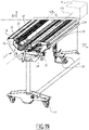
- Denim yarns are drawn-in with a drawing-in machine represented on figures 14 and 15 , whose yarn frame 12 and drawing-in unit 8 are slightly different from the ones of the first embodiment.
- no maintaining device is provided, in the meaning of maintaining device 26 of the first embodiment.
- the rubber profile 34 is located only above the main plane P22, whereas the clamping rail 22 delimits the clamping volume V22 on the other side of the main plane P22, that is under the main plane P22.
- the clamping direction of rotation R2 is counterclockwise on the figure, as in the second embodiment, whereas it is clockwise in the first and third embodiments.
- the planar internal surface 36 of the rubber profile 34 is oriented toward the opening 022 and has an inclination angle ⁇ between 10° and 30°, preferably equal to about 16°, with respect to a main plane P22 of the rail 22.
- This angle ⁇ is also defined by the orientation of the bottom of the notch 32, since the rubber profile has a rectangular cross section.
- the internal surface 36 of the rubber profile 34 is also inclined with regard to the axis Z22 and parallel to the axis X22.
- the section of the clamping rod 24 is the same along its whole length. It defines a circular surface 48 and a planar surface 50, comparable to surfaces 48 and 50 of the first embodiment. These surfaces extend up to the two end portions 44 of the clamping rod, which are directly adjacent to the central portion 42, without interposition of an intermediate portion 46.
- insertion of the clamping rod 24 into the clamping volume V22 occurs through the opening O22, as in the first embodiment, up to a position where its longitudinal axis X24 superposes with the longitudinal axis X22 of the clamping rail, on the rotation axis X20.
- the clamping rod is rotated in the clamping direction R2, around the rotation axis, with a non-represented tool, which has an inner shape complementary to the cross section of the clamping rod 24.
- This rotation in the clamping direction R2 goes on up to when the clamping rod reaches the intermediate position represented in the center of figure 13 , where a clearance C22 exists between the clamping rod 24 and the internal surface 36 of the rubber profile 34.
- This clearance C22 allows the yarns to move within the clamping volume V22.
- this clearance C22 has a non-zero width larger than the thickness of the yarns. Therefore, the operator can use this intermediate position to adjust the repartition of warp yarns 200 along the longitudinal axis X22, thus to make the yarn tension distribution more even along the clamping rail 22.
- the planar surface 50 faces the internal surface 36.
- the clamping rod In this intermediate position and in the clamping position, the clamping rod cannot be fully extracted from the clamping volume V22 through the opening O22, for the same reasons as the ones mentioned for the first embodiment, in particular because the ratio d24/W22 is strictly larger than 1 and because of the retaining zone formed by the portions 30a and 30b of the inner cylindrical surface 30.
- the dimension d24 and width W22 are measured at the same longitudinal level along the rotation axis X20.
- the clamping rod 24 is held in the intermediate position by the operator using the non-represented tool for exerting a torque around the rotation axis X20, against the reaction effort of the yarns, which tends to rotate the clamping rod in a direction opposite to the direction of rotation R2.
- the parameters defined as for the first embodiment have the following values :
- Rotation angle between the intermediate and clamping positions in the clamping direction R2 40°.
- the diameter D1 is strictly smaller than the diameter D30, which is well adapted to the case of Denim yarns, which are relatively thick.
- the ratio D1/D30 is adapted to the thickness of the yarns to be clamped and is in a range between 0,98 and 1.
- the portion 30a starts on the edge of the opening O22 on the side of the main plane P22 opposite to the rubber profile 34.
- the value of the angle ⁇ helps centering the portion 30a, in relation to the axis X22, with respect to the internal surface 36.
- the portion 30a extends angularly, around the longitudinal axis X22 and over a first angular sector with an apex angle ⁇ , up to a transition step 33.
- the value of angle ⁇ is between 30 and 50°, preferably equal to 40°.
- the side planar surface of the rubber profile 34 forming the internal surface 36 extends angularly, around the longitudinal axis X22 and over a second angular sector with an apex angle ⁇ .
- angle ⁇ is between 30 and 65°, preferably equal to 55°.
- This second angular sector is opposite, with regard to the rotation axis X20, to the first angular sector of the portion 30a.
- the internal surface 36 faces the portion 30a, with the axis X22 in between.
- the transition step 33 is opposite to the opening O22 with respect to a plane formed by the axis Z22 and the longitudinal axis X22.
- the portion 30a goes, from the edge of the opening O22, up to beyond the longitudinal axis X22, along the transverse axis Y22.
- the clamping rod 24 when the clamping rod 24 is in the clamping position, it cooperates with the portion 30a in both opposite transverse directions parallel to transverse axis Y22. This accurately positions the clamping rod 24 in the clamping volume V22 along transverse axis Y22.
- the portion 30b starts on the edge of the opening O22 which is on the same side of the main plane P22 as the internal surface 36 and the portion 30b extends up to the internal surface 36.
- the clamping rod 24 partially protrudes out of the clamping volume V22.
- the clamping rod 24 partially protrudes out of the clamping rail 22, beyond the two portions of the front face 23, which are situated on both sides of the main plane P22, respectively over a non-zero distance d5.
- the clamping rod 24 partially protrudes through the opening O22 and out of the clamping rail 22.
- the effort exerted on the clamping rod 24 by the warp yarns 200 and by the rubber profile 34, in a direction parallel to axis Y22 is oriented to the right on figure 13 .
- a reaction force exerted by the portions 30a and 30b of the inner cylindrical surface 30 of the rail 22 on the circular surface 48 of the clamping rod is oriented to the left on figure 13 and defined by the geometry of surfaces 30 and 48.
- the ration d5/d2 is chosen between 0.1 and 0.2, preferably equal to about 0.15.
- the yarn frame 12 of this fourth embodiment is represented on figure 14 .
- the warp yarns 200 are pulled from the warp beam first on the side of the lower longitudinal beam 16B, then on the side of the upper longitudinal beam 16B.
- the lower yarn-clamping device 20B2 is detachable, as considered here above, in a non-represented embodiment, alternative to the first embodiment.
- the two longitudinal grooves 184 of a rail 22 have the same geometry and are offset along the axis Y22, by a non-zero distance d6.
- the value of d6 can be chosen between 1 and 5 mm, preferably equal to 2 mm.
- grooves 184 are also offset in the first embodiment, the layers L1 and L2 are also offset in this embodiment, as can be derived from figures 7 and 8 .
- Two yarn-clamping devices 20 are slidable, along directions parallel to the respective rotation axes X20 and longitudinal axes X22, namely the lower yarn-clamping device 20B2 and the upper yarn-clamping device 20A2 as in the first embodiment.
- the displacements of the yarn-clamping devices 20A2 and 20B2 are each controlled by one adjusting device 160.
- the adjusting device associated to the lower slidable yarn-clamping device 20B2 is separated from the rest of the yarn frame 12 and shown on a larger scale on figure 14 .
- Each adjusting device 160 includes a hand wheel 168 which drives a parallel gear 166, whereas a nut 162 is mounted on an output spindle of the parallel gear 166, as in the first embodiment.
- a housing 171 is provided on the nut 162 for connecting the nut to a non-represented protrusion, e.g. a pin, of the corresponding clamping rail 22.
- the housing 171 fulfills a function similar to the function of the bolt 170 of the first embodiment.
- the drawing-in unit 8 moves parallel to the longitudinal axes X22 of the clamping rails 22.
- the drawing-in unit 8 is equipped with a top guide roller 81 and a bottom guide roller 83.
- the top guide roller 81 is mounted on, and secured to, the drawing-in unit 8 and freely rotatable around a rotation axis Z81
- the bottom guide roller 83 is also mounted on, and secured to, the drawing-in unit and freely rotatable around another rotation axis Z83.
- the axes Z81 and Z83 are parallel to each other and to the yarns 200 in the yarn layers L1 and L2.
- each roller 81 or 83 is in contact with, and rolls against, a portion of the circular surface 48 of a clamping rod 24, which protrudes partially out of the clamping rail 22 of a yarn-clamping device 20 which belongs to the second pair of yarn clamping devices 20A2, 20B2. As shown on figure 15 , this allows guiding the longitudinal movement of the drawing-in unit 8 along the longitudinal axis X22 of each clamping rail 22 and positioning the drawing-in unit with respect to the yarn layers L1 and L2.
- only one roller 81 or 83 is provided for guiding the drawing-in unit parallel to the longitudinal axis X22 of a clamping rail 22.
- the internal surface 36 of the rubber profile is curved, in particular concave.
- the bottom of the notch 32 is also curved, in particular concave, with globally the same cross-section as the internal surface 36.
- the internal surface 36 as a cross-section in the form of an arc of a circle, with a diameter slightly smaller than the diameter of the adjacent portion 30b of the inner surface 30.
- the internal surface 36 projects, at least partially, into a cylindrical volume whose diameter is equal to the maximum dimension of the clamping rod, i.e. equal to diameter D1, and which is delimited in the clamping volume V22 all around the rotation axis X24 of the clamping rod 24.
- the portion 30b of the inner surface 30 forms, together with the other portion 30a of this surface 30, a retaining zone for blocking the clamping rod 24 within the clamping volume V22 in the clamping position of the clamping rod 24.
- a retaining zone for blocking the clamping rod 24 within the clamping volume V22 is also formed by the inner surface 30 in the intermediate position and between the intermediate position and the clamping position when the clamping rod 24 is rotated in the clamping direction R2.
- the inclination angle ⁇ of the internal surface 36 is the mean inclination angle. Its value is between 10° and 30°, preferably equal to about 16°.
- the rotation angle between the insertion and intermediate positions preferably in the clamping direction R2 equals 45° and the rotation angle between the intermediate and clamping positions in the clamping direction R2 preferably equals 40°.
- the part of the clamping rod 24 penetrating the internal surface 36 is a portion of the circular surface 48 instead of the edge 49, as the previous embodiments.
- the clamping rod 24 partially protrudes, through the opening O22, out of the clamping rail 22.
- the clamping rod 24 partially protrudes out of the clamping volume V22 and beyond the two portions of the front face 23, which are situated on both sides of the main plane P22, over a non-zero distance d5, as in the fourth embodiment.
- the ratio d24/W22 is strictly larger than 1 and a retaining zone of the clamping rod 24 is formed by the portions 30a and 30b of the inner cylindrical surface 30 for blocking the clamping rod 24 within the clamping volume V22.
- the dimension d24 and width W22 are measured at the same longitudinal level along the rotation axis X20.
- the clamping rod 24 is hollow as in the second embodiment.
- the external cross-section of the clamping rod 24 defines a circular surface 48, made of two portions 48a and 48b centered on the longitudinal axis X24, and two parallel and opposite planar surfaces 50a and 50b.
- the two portions 30a and 30b of the inner surface 30 of the clamping rail together form a retaining zone for blocking the clamping rod 24 within the clamping volume V22, at least when it is in the clamping position represented on figure 17 , where the maximal external dimension d24 of its cross section is strictly larger than the width W22 of the opening O22 of the clamping volume, these dimension and width being measured at the same longitudinal level along the rotation axis X20.
- the retaining zone of the clamping rail 22 is formed by the two cylindrical portions 30a and 30b.
- the circular surface 48 and the portions 30a, 30b cooperate in a form-fitting manner, with the yarns 200 in-between, in the clamping position of the clamping rod 24.
- the portion 30b of the inner surface 30 is cylindrical, with a cross section in the form of an arc of a circle centered on axis X24.
- the portion 30a does not have a cross section in the form of an arc of a circle.
- the portion 30a comprises several surfaces 30a1, 30a2 and 30a3.
- Surface 30a1 is a convex surface forming a transition between the edge of the opening O22 and a surface 30a2 perpendicular to axis Y22 and parallel to axes X22 and Z22.
- Surface 30a3 is a planar surface which is perpendicular to axis Z22 and parallel to axes X22 and Y22.
- the surface 30a1 is at least partially turned toward the bottom of the clamping volume V22 at the opposite of the opening O22 along the transverse axis Y22.
- the surfaces 30a1 and 30a3 cooperate with the clamping rod 24, with the yarns in-between, in the clamping position represented on figure 18 .
- the portion 30a also defines, together with the portion 30b, a retaining zone for blocking the clamping rod 24 within the clamping volume V22 in the clamping position of the rod.
- the surface 30a1 cooperates along the transverse direction Y22 with the circular surface 48 of the clamping rod 24, with the yarns 200 in-between.
- the portion 30b and the circular surface 48 cooperate together in a form-fitting manner, with the yarns 200 in-between.
- the ratio d24/W22 is strictly larger than 1, with dimension d24 and width W22 defined as in the first embodiment.
- the dimension d24 and width W22 are measured at the same longitudinal level along the rotation axis X20.
- the clamping rail 22 is formed of two parts 22a and 22b secured together, e.g. by screws or by welding. These two parts cannot have a relative movement. As for all the other embodiments, the portions 30a and 30b have no possibility of relative movement with regard to the notch 32 housing the rubber profile 34 in the clamping rail 22.
- the yarn-clamping devices 20 of the second to seventh embodiments can be used instead of the ones of the first embodiment, in the drawing-in machine 2 and tying installation 3 of figures 1 to 3 and 19 .
- the internal surface 36 of the single rubber profile is located on a single side of the main plane P22 and partly delimits the clamping volume V22, whereas the clamping rail fully delimits this clamping volume V22 on the other side of the main plane P22.
- the internal surface 36 shall be considered as the portion of surface of the rubber profile 34 that the clamping rod 24 penetrates during the clamping process.
- the yarn frame may include a single pair or yarn-clamping devices.
- a single yarn-clamping device can be used for clamping yarns of different overlapping yarn layers.
- the lowermost and uppermost clamping devices 20A2 and 20B2 are fixed on the upper and lower beams 16 without possibility of translation along axis X22, whereas the other two clamping devices 20A1 and 20B1, that is the clamping devices handling the first layer L1, are movable along the beams 16 under the action of the adjusting devices 160.
- the maximum external dimension d24 of the clamping rod cross section, measured parallel to the axis Z22, is not equal to diameter D1 of the clamping rod 24 and the planar surface 50 is not parallel to axis Z22.
- the retaining zone in the clamping position, extends only on a single side of the main plane P22, preferably on the side of the main plane P22 that is opposite to the internal surface 36.
- the angles of 40°, 45°, 50° and 90° mentioned here above may vary.
- the first angle for the amplitude of rotation of the clamping rod 24 between the insertion position and the intermediate position in the clamping direction R2 may be between 30° and 55°, depending on the position of the internal surface 36 within the clamping volume V22.
- the second angle for the amplitude of rotation of the clamping rod 24 between the insertion position and the clamping position in the clamping direction R2 can be between 80° and 100°.
- a yarn-clamping device 20 includes a single maintaining device 26 mounted at a first end of its clamping rail 22 for cooperating with an intermediate portion 46 located next to a first end of the of the clamping rod 24.
- a rod holder is located at the second end of the clamping rail, for holding a second end of the clamping rod opposite to the intermediate portion with regard to the clamping rail.
- the second end of the clamping rod is inserted first in the rod holder, then the clamping rod is tilted so that its central portion enters the clamping volume and its intermediate portion enters the housing of the maintaining device.
- the rod does not have a purely translational movement and is inclined relative to the longitudinal axis of the clamping rail.
- the body 60 is provided with an indexing pin protruding in the housing H26 and configured to engage in a circumferential limited recess provided on the outer cylindrical surface 120 of the retaining member 76, in order to allow movement of the retaining member 76 only within the angular range delimited between the release position and the third position reached when the clamping rod rotates in the clamping direction between its insertion position and its clamping position.
- a rotation on 360° is, in that case, not possible for the retaining member 76.
- an insertion of the clamping rod 24 in an insertion position where the planar surface 50 of the clamping rod 24 doesn't face the internal surface 36 is impossible in that case.
- the translation direction A90 of a slidable obstacle forming part 90 is not parallel to the axis Z20 but, for example, inclined with regard to axes Z60 and Y60.
- the spring 92 is omitted.
- the obstacle can be weighted so that it is movable from its retracted position to its blocking position and maintained in blocking position due to gravity.
- the maintaining device may comprise only an obstacle.
- the clamping rod is made up of different longitudinal portions of different cross-sections, hollow or not hollow, assembled together.
- the clamping rod 24 in the intermediate position and in the clamping position of the clamping rod 24, and when the clamping rod 24 rotates in the clamping direction R2 between the intermediate position and the clamping position, the clamping rod 24 cooperates along the transverse direction Y22 with the inner surface 30 by abutment against the inner surface 30 in the transverse direction Y22 opposite to the translational movement A1, with the yarns 200 in-between.
- the clamping rail 22 thus forms a retaining zone for blocking the clamping rod 24 within the clamping volume V22 such that the clamping rod 24 cannot be fully extracted from the clamping volume V22 through the opening O22 with only a transverse movement opposite to translational movement A1 at least in the clamping position.
- the retaining zone blocks the clamping rod 24 within the clamping volume V22 in a position in which the clamping rod 24 protrudes out of the clamping rail 22 through the opening 022, as for the fourth, fifth and seventh embodiments, or doesn't protrude.
- the rubber profile 34 creates, on the clamping rod 24, an elastic force toward the opening O22 along the transverse axis Y22. Because the internal surface 36 is inclined with an angle ⁇ between 10° and 30° with regard to the main plane P22, when the clamping rod 24 penetrates the internal surface 36, the rubber profile 34 also creates, on the clamping rod 24, an elastic force along axis Z22 in the direction of the inner surface of the clamping rail 22 that delimits the clamping volume V22 on the side of the main plane P22 opposite to the internal surface 36.
- yarn-clamping devices 20 according to the invention and a yarn frame 12 according to the invention can also be used in a warp tying installation 3 where two pairs of yarn-clamping devices 20 are mounted one above the other along the axis Z22 of a yarn frame 12 in a tying configuration. Each pair pairs of yarn-clamping devices 20 is dedicated to one warp layer.
- the yarn frame 12 is configured for guiding the translation of a tying unit 8' along its longitudinal axis X12.
- the two pairs of yarn-clamping devices 20 are movable relative to one another along the longitudinal axis X12, as known for example from EP-A-1 943 381 , for relative movement of the two layers, these layers extending in two parallel and spaced planes.
- the frame 12 can be movable and equipped with rollers 13 as shown on figure 19 , or stationary in a variant.
Landscapes
- Engineering & Computer Science (AREA)
- Textile Engineering (AREA)
- Spinning Or Twisting Of Yarns (AREA)
- Warping, Beaming, Or Leasing (AREA)
- Looms (AREA)
Priority Applications (2)
| Application Number | Priority Date | Filing Date | Title |
|---|---|---|---|
| TW111102921A TW202235716A (zh) | 2021-01-25 | 2022-01-24 | 夾紗裝置、紗架及具備該夾紗裝置的穿經機 |
| CN202210088778.7A CN114790604B (zh) | 2021-01-25 | 2022-01-25 | 纱线夹紧装置,纱线框架和包括这种纱线夹紧装置的穿经机 |
Applications Claiming Priority (1)
| Application Number | Priority Date | Filing Date | Title |
|---|---|---|---|
| EP21153267.6A EP4033020B1 (fr) | 2021-01-25 | 2021-01-25 | Dispositif de serrage de fil, cadre de fil et machine d'étirage comprenant un tel dispositif de serrage de fil, procédé de serrage de fil doté d'un dispositif de serrage de fil |
Publications (2)
| Publication Number | Publication Date |
|---|---|
| EP4033021A1 true EP4033021A1 (fr) | 2022-07-27 |
| EP4033021B1 EP4033021B1 (fr) | 2024-10-09 |
Family
ID=74236066
Family Applications (2)
| Application Number | Title | Priority Date | Filing Date |
|---|---|---|---|
| EP21153267.6A Active EP4033020B1 (fr) | 2021-01-25 | 2021-01-25 | Dispositif de serrage de fil, cadre de fil et machine d'étirage comprenant un tel dispositif de serrage de fil, procédé de serrage de fil doté d'un dispositif de serrage de fil |
| EP21177451.8A Active EP4033021B1 (fr) | 2021-01-25 | 2021-06-02 | Dispositif de serrage de fil, cadre de fil et d'étirage comprenant un tel dispositif de serrage de fil |
Family Applications Before (1)
| Application Number | Title | Priority Date | Filing Date |
|---|---|---|---|
| EP21153267.6A Active EP4033020B1 (fr) | 2021-01-25 | 2021-01-25 | Dispositif de serrage de fil, cadre de fil et machine d'étirage comprenant un tel dispositif de serrage de fil, procédé de serrage de fil doté d'un dispositif de serrage de fil |
Country Status (3)
| Country | Link |
|---|---|
| EP (2) | EP4033020B1 (fr) |
| CN (2) | CN114790605B (fr) |
| TW (1) | TW202235716A (fr) |
Cited By (2)
| Publication number | Priority date | Publication date | Assignee | Title |
|---|---|---|---|---|
| CN116065295A (zh) * | 2022-12-26 | 2023-05-05 | 绍兴超弦针纺有限公司 | 一种辅助上纱的自动结经机 |
| EP4685280A1 (fr) | 2024-07-25 | 2026-01-28 | Stäubli Sargans AG | Cadre de serrage, machine d'insertion comprenant un tel cadre de serrage et procédé d'insertion utilisant un tel cadre de serrage |
Families Citing this family (2)
| Publication number | Priority date | Publication date | Assignee | Title |
|---|---|---|---|---|
| EP4033020B1 (fr) * | 2021-01-25 | 2024-12-18 | Stäubli Sargans AG | Dispositif de serrage de fil, cadre de fil et machine d'étirage comprenant un tel dispositif de serrage de fil, procédé de serrage de fil doté d'un dispositif de serrage de fil |
| EP4553208A1 (fr) | 2023-11-13 | 2025-05-14 | Stäubli Sargans AG | Dispositif de serrage pour une machine d'étirage, machine d'étirage comprenant un tel dispositif de serrage et procédé d'étirage correspondant |
Citations (7)
| Publication number | Priority date | Publication date | Assignee | Title |
|---|---|---|---|---|
| SU93498A1 (ru) * | 1951-01-29 | 1951-11-30 | К.С. Коротаев | Приспособление дл сращивани концов нитей сработанной и вновь заправл емой основ |
| DE1174267B (de) * | 1958-03-26 | 1964-07-16 | Knotex Maschb Ges M B H | Vorrichtung fuer einen Bandwebstuhl zum Halten der durch Ankergewichte belasteten Kettenfaeden |
| US5381594A (en) | 1990-10-23 | 1995-01-17 | Zellweger Uster Ag | Machine for the automatic drawing-in of warp threads having warp beam truck |
| EP1943381A1 (fr) | 2006-10-06 | 2008-07-16 | Stäubli AG Pfäffikon | Dispositif et procede de liaison de fils de chaine de differentes couches de fils de differentes chaines de tissage |
| EP2199443A1 (fr) | 2008-12-19 | 2010-06-23 | Stäubli AG Pfäffikon | Unité mobile pour le rentrage de la chaine |
| EP2662481A1 (fr) | 2012-05-10 | 2013-11-13 | Stäubli Sargans AG | Dispositif de serrage, machine à enverjure, machine de passage et procédé de tension de plusieurs fils de chaîne |
| CN211036281U (zh) | 2019-09-18 | 2020-07-17 | 史陶比尔萨尔甘斯股份公司 | 纱线分离单元和穿经机 |
Family Cites Families (12)
| Publication number | Priority date | Publication date | Assignee | Title |
|---|---|---|---|---|
| DE2847520C3 (de) * | 1978-11-02 | 1981-08-06 | Lindauer Dornier-Gesellschaft Mbh, 8990 Lindau | Vorrichtung zum Vorlegen von Kettfäden für das automatische Einziehen derselben in Litzen und Lamellen einer Webmaschine |
| CH683784A5 (de) * | 1991-09-17 | 1994-05-13 | Zellweger Uster Ag | Klemmvorrichtung für eine Fadenschicht und Verwendung derselben. |
| US5390708A (en) * | 1993-09-21 | 1995-02-21 | Asten Group, Inc. | Apparatus for translating yarns in the proper position and orientation for forming a woven join |
| WO1999014411A1 (fr) * | 1997-09-15 | 1999-03-25 | Stäubli Ag Pfäffikon | Dispositif permettant de tendre des fils de chaine sur une machine a tendre les fils de chaine |
| EP2123811A1 (fr) * | 2008-05-23 | 2009-11-25 | Maschinenfabrik Rieter Ag | Machine à filer ou retordeuse |
| EP2388362B1 (fr) * | 2010-05-21 | 2012-12-26 | Stäubli AG Pfäffikon | Dispositif de tension et procédé destiné à retendre des fils de chaîne d'une couche de fils de chaîne |
| CN105714458A (zh) * | 2016-04-18 | 2016-06-29 | 句容兴云纺织品有限公司 | 接经机夹纱装置 |
| CN105714461A (zh) * | 2016-04-18 | 2016-06-29 | 句容兴云纺织品有限公司 | 一种结经机夹纱装置 |
| EP3330418B1 (fr) * | 2016-12-01 | 2019-06-26 | Stäubli Sargans AG | Module de séparation de fils avec un dispositif capteur capacitif |
| CN209082120U (zh) * | 2018-07-27 | 2019-07-09 | 嘉兴市前荣织造有限公司 | 一种自动穿经机 |
| CN111663233B (zh) * | 2020-07-12 | 2024-04-09 | 诸暨市捷速尔纺织机械有限公司 | 双轴头穿棕机 |
| EP4033020B1 (fr) * | 2021-01-25 | 2024-12-18 | Stäubli Sargans AG | Dispositif de serrage de fil, cadre de fil et machine d'étirage comprenant un tel dispositif de serrage de fil, procédé de serrage de fil doté d'un dispositif de serrage de fil |
-
2021
- 2021-01-25 EP EP21153267.6A patent/EP4033020B1/fr active Active
- 2021-06-02 EP EP21177451.8A patent/EP4033021B1/fr active Active
-
2022
- 2022-01-24 TW TW111102921A patent/TW202235716A/zh unknown
- 2022-01-25 CN CN202210090012.2A patent/CN114790605B/zh active Active
- 2022-01-25 CN CN202210088778.7A patent/CN114790604B/zh active Active
Patent Citations (7)
| Publication number | Priority date | Publication date | Assignee | Title |
|---|---|---|---|---|
| SU93498A1 (ru) * | 1951-01-29 | 1951-11-30 | К.С. Коротаев | Приспособление дл сращивани концов нитей сработанной и вновь заправл емой основ |
| DE1174267B (de) * | 1958-03-26 | 1964-07-16 | Knotex Maschb Ges M B H | Vorrichtung fuer einen Bandwebstuhl zum Halten der durch Ankergewichte belasteten Kettenfaeden |
| US5381594A (en) | 1990-10-23 | 1995-01-17 | Zellweger Uster Ag | Machine for the automatic drawing-in of warp threads having warp beam truck |
| EP1943381A1 (fr) | 2006-10-06 | 2008-07-16 | Stäubli AG Pfäffikon | Dispositif et procede de liaison de fils de chaine de differentes couches de fils de differentes chaines de tissage |
| EP2199443A1 (fr) | 2008-12-19 | 2010-06-23 | Stäubli AG Pfäffikon | Unité mobile pour le rentrage de la chaine |
| EP2662481A1 (fr) | 2012-05-10 | 2013-11-13 | Stäubli Sargans AG | Dispositif de serrage, machine à enverjure, machine de passage et procédé de tension de plusieurs fils de chaîne |
| CN211036281U (zh) | 2019-09-18 | 2020-07-17 | 史陶比尔萨尔甘斯股份公司 | 纱线分离单元和穿经机 |
Cited By (2)
| Publication number | Priority date | Publication date | Assignee | Title |
|---|---|---|---|---|
| CN116065295A (zh) * | 2022-12-26 | 2023-05-05 | 绍兴超弦针纺有限公司 | 一种辅助上纱的自动结经机 |
| EP4685280A1 (fr) | 2024-07-25 | 2026-01-28 | Stäubli Sargans AG | Cadre de serrage, machine d'insertion comprenant un tel cadre de serrage et procédé d'insertion utilisant un tel cadre de serrage |
Also Published As
| Publication number | Publication date |
|---|---|
| EP4033020A1 (fr) | 2022-07-27 |
| TW202235716A (zh) | 2022-09-16 |
| CN114790604A (zh) | 2022-07-26 |
| CN114790605A (zh) | 2022-07-26 |
| CN114790604B (zh) | 2025-08-26 |
| CN114790605B (zh) | 2025-08-22 |
| EP4033020B1 (fr) | 2024-12-18 |
| EP4033021B1 (fr) | 2024-10-09 |
Similar Documents
| Publication | Publication Date | Title |
|---|---|---|
| EP4033021B1 (fr) | Dispositif de serrage de fil, cadre de fil et d'étirage comprenant un tel dispositif de serrage de fil | |
| CH631756A5 (de) | Spannbaumvorrichtung einer webmaschine. | |
| US4923571A (en) | Apparatus for spacing apart containers that are conveyed close to each other in a single lane | |
| US3884274A (en) | Loom warp beam device | |
| EP0374496B1 (fr) | Positionneurs pour les bords avant de feuilles | |
| EP0565934B1 (fr) | Métier à tisser modulaire | |
| DE102022210530B4 (de) | Rundkamm für eine Kämmmaschine | |
| EP0620304A1 (fr) | Méthode et dispositif pour changer l'article | |
| DE3038234A1 (de) | Greiferhebel mit greiferfingern fuer greifer von industrierobotern | |
| PL204880B1 (pl) | Krosno do tkania dywanów | |
| US5305801A (en) | Apparatus for prepositioning and delivering heald shafts in looms | |
| US5148585A (en) | Device for manipulating drop wires for warp-thread drawing-in machines | |
| EP0683009B1 (fr) | Dispositif de guidage pour machines à meuler | |
| GB2115021A (en) | Loom having shed-forming weaving discs | |
| WO1992007127A1 (fr) | Machine de passage automatique des fils de chaine | |
| EP4726087A1 (fr) | Poste de tirage et machine de tirage comprenant un tel poste de tirage | |
| CN114232184A (zh) | 一种用于储纬器的瓷眼支架及其制造方法 | |
| DE102024102863B4 (de) | Mehrfachschraubvorrichtung zum Anschrauben wenigstens zweier Schraubmittel und Verfahren zum Anschrauben wenigstens zweier Schraubmittel | |
| EP1177339A1 (fr) | Dispositif et procede pour le transfert d'elements de harnais separes a un dispositif de transport | |
| DE4101532A1 (de) | Spreizwerkzeug | |
| EP1732722A1 (fr) | Mandrin de serrage pour la reception d'une piece a usiner | |
| CH300670A (de) | Maschine zum Erzeugen unter sich paralleler Nuten und Löcher in einem Werkstück. | |
| CN120486018A (zh) | 停经片传送模块和包括这种传送模块的穿经机 | |
| CN120395314A (zh) | 一种机床组件焊接用定位工装 | |
| DE15729C (de) | Steinnufsknopf-Drehbank |
Legal Events
| Date | Code | Title | Description |
|---|---|---|---|
| PUAI | Public reference made under article 153(3) epc to a published international application that has entered the european phase |
Free format text: ORIGINAL CODE: 0009012 |
|
| STAA | Information on the status of an ep patent application or granted ep patent |
Free format text: STATUS: THE APPLICATION HAS BEEN PUBLISHED |
|
| AK | Designated contracting states |
Kind code of ref document: A1 Designated state(s): AL AT BE BG CH CY CZ DE DK EE ES FI FR GB GR HR HU IE IS IT LI LT LU LV MC MK MT NL NO PL PT RO RS SE SI SK SM TR |
|
| STAA | Information on the status of an ep patent application or granted ep patent |
Free format text: STATUS: REQUEST FOR EXAMINATION WAS MADE |
|
| 17P | Request for examination filed |
Effective date: 20221227 |
|
| RBV | Designated contracting states (corrected) |
Designated state(s): AL AT BE BG CH CY CZ DE DK EE ES FI FR GB GR HR HU IE IS IT LI LT LU LV MC MK MT NL NO PL PT RO RS SE SI SK SM TR |
|
| GRAP | Despatch of communication of intention to grant a patent |
Free format text: ORIGINAL CODE: EPIDOSNIGR1 |
|
| STAA | Information on the status of an ep patent application or granted ep patent |
Free format text: STATUS: GRANT OF PATENT IS INTENDED |
|
| INTG | Intention to grant announced |
Effective date: 20240605 |
|
| GRAS | Grant fee paid |
Free format text: ORIGINAL CODE: EPIDOSNIGR3 |
|
| GRAA | (expected) grant |
Free format text: ORIGINAL CODE: 0009210 |
|
| STAA | Information on the status of an ep patent application or granted ep patent |
Free format text: STATUS: THE PATENT HAS BEEN GRANTED |
|
| AK | Designated contracting states |
Kind code of ref document: B1 Designated state(s): AL AT BE BG CH CY CZ DE DK EE ES FI FR GB GR HR HU IE IS IT LI LT LU LV MC MK MT NL NO PL PT RO RS SE SI SK SM TR |
|
| REG | Reference to a national code |
Ref country code: CH Ref legal event code: EP |
|
| REG | Reference to a national code |
Ref country code: DE Ref legal event code: R096 Ref document number: 602021019786 Country of ref document: DE |
|
| REG | Reference to a national code |
Ref country code: IE Ref legal event code: FG4D |
|
| REG | Reference to a national code |
Ref country code: LT Ref legal event code: MG9D |
|
| REG | Reference to a national code |
Ref country code: NL Ref legal event code: MP Effective date: 20241009 |
|
| REG | Reference to a national code |
Ref country code: AT Ref legal event code: MK05 Ref document number: 1730696 Country of ref document: AT Kind code of ref document: T Effective date: 20241009 |
|
| PG25 | Lapsed in a contracting state [announced via postgrant information from national office to epo] |
Ref country code: NL Free format text: LAPSE BECAUSE OF FAILURE TO SUBMIT A TRANSLATION OF THE DESCRIPTION OR TO PAY THE FEE WITHIN THE PRESCRIBED TIME-LIMIT Effective date: 20241009 |
|
| PG25 | Lapsed in a contracting state [announced via postgrant information from national office to epo] |
Ref country code: NL Free format text: LAPSE BECAUSE OF FAILURE TO SUBMIT A TRANSLATION OF THE DESCRIPTION OR TO PAY THE FEE WITHIN THE PRESCRIBED TIME-LIMIT Effective date: 20241009 |
|
| PG25 | Lapsed in a contracting state [announced via postgrant information from national office to epo] |
Ref country code: PT Free format text: LAPSE BECAUSE OF FAILURE TO SUBMIT A TRANSLATION OF THE DESCRIPTION OR TO PAY THE FEE WITHIN THE PRESCRIBED TIME-LIMIT Effective date: 20250210 Ref country code: IS Free format text: LAPSE BECAUSE OF FAILURE TO SUBMIT A TRANSLATION OF THE DESCRIPTION OR TO PAY THE FEE WITHIN THE PRESCRIBED TIME-LIMIT Effective date: 20250209 Ref country code: HR Free format text: LAPSE BECAUSE OF FAILURE TO SUBMIT A TRANSLATION OF THE DESCRIPTION OR TO PAY THE FEE WITHIN THE PRESCRIBED TIME-LIMIT Effective date: 20241009 |
|
| PG25 | Lapsed in a contracting state [announced via postgrant information from national office to epo] |
Ref country code: FI Free format text: LAPSE BECAUSE OF FAILURE TO SUBMIT A TRANSLATION OF THE DESCRIPTION OR TO PAY THE FEE WITHIN THE PRESCRIBED TIME-LIMIT Effective date: 20241009 |
|
| PG25 | Lapsed in a contracting state [announced via postgrant information from national office to epo] |
Ref country code: BG Free format text: LAPSE BECAUSE OF FAILURE TO SUBMIT A TRANSLATION OF THE DESCRIPTION OR TO PAY THE FEE WITHIN THE PRESCRIBED TIME-LIMIT Effective date: 20241009 |
|
| PG25 | Lapsed in a contracting state [announced via postgrant information from national office to epo] |
Ref country code: ES Free format text: LAPSE BECAUSE OF FAILURE TO SUBMIT A TRANSLATION OF THE DESCRIPTION OR TO PAY THE FEE WITHIN THE PRESCRIBED TIME-LIMIT Effective date: 20241009 |
|
| PG25 | Lapsed in a contracting state [announced via postgrant information from national office to epo] |
Ref country code: NO Free format text: LAPSE BECAUSE OF FAILURE TO SUBMIT A TRANSLATION OF THE DESCRIPTION OR TO PAY THE FEE WITHIN THE PRESCRIBED TIME-LIMIT Effective date: 20250109 |
|
| PG25 | Lapsed in a contracting state [announced via postgrant information from national office to epo] |
Ref country code: LV Free format text: LAPSE BECAUSE OF FAILURE TO SUBMIT A TRANSLATION OF THE DESCRIPTION OR TO PAY THE FEE WITHIN THE PRESCRIBED TIME-LIMIT Effective date: 20241009 Ref country code: GR Free format text: LAPSE BECAUSE OF FAILURE TO SUBMIT A TRANSLATION OF THE DESCRIPTION OR TO PAY THE FEE WITHIN THE PRESCRIBED TIME-LIMIT Effective date: 20250110 Ref country code: AT Free format text: LAPSE BECAUSE OF FAILURE TO SUBMIT A TRANSLATION OF THE DESCRIPTION OR TO PAY THE FEE WITHIN THE PRESCRIBED TIME-LIMIT Effective date: 20241009 |
|
| PG25 | Lapsed in a contracting state [announced via postgrant information from national office to epo] |
Ref country code: PL Free format text: LAPSE BECAUSE OF FAILURE TO SUBMIT A TRANSLATION OF THE DESCRIPTION OR TO PAY THE FEE WITHIN THE PRESCRIBED TIME-LIMIT Effective date: 20241009 |
|
| PG25 | Lapsed in a contracting state [announced via postgrant information from national office to epo] |
Ref country code: RS Free format text: LAPSE BECAUSE OF FAILURE TO SUBMIT A TRANSLATION OF THE DESCRIPTION OR TO PAY THE FEE WITHIN THE PRESCRIBED TIME-LIMIT Effective date: 20250109 |
|
| PG25 | Lapsed in a contracting state [announced via postgrant information from national office to epo] |
Ref country code: SM Free format text: LAPSE BECAUSE OF FAILURE TO SUBMIT A TRANSLATION OF THE DESCRIPTION OR TO PAY THE FEE WITHIN THE PRESCRIBED TIME-LIMIT Effective date: 20241009 |
|
| PGFP | Annual fee paid to national office [announced via postgrant information from national office to epo] |
Ref country code: DE Payment date: 20250627 Year of fee payment: 5 |
|
| PG25 | Lapsed in a contracting state [announced via postgrant information from national office to epo] |
Ref country code: DK Free format text: LAPSE BECAUSE OF FAILURE TO SUBMIT A TRANSLATION OF THE DESCRIPTION OR TO PAY THE FEE WITHIN THE PRESCRIBED TIME-LIMIT Effective date: 20241009 |
|
| REG | Reference to a national code |
Ref country code: DE Ref legal event code: R097 Ref document number: 602021019786 Country of ref document: DE |
|
| PGFP | Annual fee paid to national office [announced via postgrant information from national office to epo] |
Ref country code: BE Payment date: 20250627 Year of fee payment: 5 |
|
| PG25 | Lapsed in a contracting state [announced via postgrant information from national office to epo] |
Ref country code: EE Free format text: LAPSE BECAUSE OF FAILURE TO SUBMIT A TRANSLATION OF THE DESCRIPTION OR TO PAY THE FEE WITHIN THE PRESCRIBED TIME-LIMIT Effective date: 20241009 |
|
| PG25 | Lapsed in a contracting state [announced via postgrant information from national office to epo] |
Ref country code: RO Free format text: LAPSE BECAUSE OF FAILURE TO SUBMIT A TRANSLATION OF THE DESCRIPTION OR TO PAY THE FEE WITHIN THE PRESCRIBED TIME-LIMIT Effective date: 20241009 |
|
| PG25 | Lapsed in a contracting state [announced via postgrant information from national office to epo] |
Ref country code: SK Free format text: LAPSE BECAUSE OF FAILURE TO SUBMIT A TRANSLATION OF THE DESCRIPTION OR TO PAY THE FEE WITHIN THE PRESCRIBED TIME-LIMIT Effective date: 20241009 |
|
| PG25 | Lapsed in a contracting state [announced via postgrant information from national office to epo] |
Ref country code: CZ Free format text: LAPSE BECAUSE OF FAILURE TO SUBMIT A TRANSLATION OF THE DESCRIPTION OR TO PAY THE FEE WITHIN THE PRESCRIBED TIME-LIMIT Effective date: 20241009 |
|
| PG25 | Lapsed in a contracting state [announced via postgrant information from national office to epo] |
Ref country code: IT Free format text: LAPSE BECAUSE OF FAILURE TO SUBMIT A TRANSLATION OF THE DESCRIPTION OR TO PAY THE FEE WITHIN THE PRESCRIBED TIME-LIMIT Effective date: 20241009 |
|
| PLBE | No opposition filed within time limit |
Free format text: ORIGINAL CODE: 0009261 |
|
| STAA | Information on the status of an ep patent application or granted ep patent |
Free format text: STATUS: NO OPPOSITION FILED WITHIN TIME LIMIT |
|
| PG25 | Lapsed in a contracting state [announced via postgrant information from national office to epo] |
Ref country code: SE Free format text: LAPSE BECAUSE OF FAILURE TO SUBMIT A TRANSLATION OF THE DESCRIPTION OR TO PAY THE FEE WITHIN THE PRESCRIBED TIME-LIMIT Effective date: 20241009 |
|
| 26N | No opposition filed |
Effective date: 20250710 |
|
| PGFP | Annual fee paid to national office [announced via postgrant information from national office to epo] |
Ref country code: CH Payment date: 20250701 Year of fee payment: 5 |
|
| PG25 | Lapsed in a contracting state [announced via postgrant information from national office to epo] |
Ref country code: MC Free format text: LAPSE BECAUSE OF FAILURE TO SUBMIT A TRANSLATION OF THE DESCRIPTION OR TO PAY THE FEE WITHIN THE PRESCRIBED TIME-LIMIT Effective date: 20241009 |
|
| PG25 | Lapsed in a contracting state [announced via postgrant information from national office to epo] |
Ref country code: LU Free format text: LAPSE BECAUSE OF NON-PAYMENT OF DUE FEES Effective date: 20250602 |
|
| GBPC | Gb: european patent ceased through non-payment of renewal fee |
Effective date: 20250602 |
|
| PG25 | Lapsed in a contracting state [announced via postgrant information from national office to epo] |
Ref country code: GB Free format text: LAPSE BECAUSE OF NON-PAYMENT OF DUE FEES Effective date: 20250602 |
|
| PG25 | Lapsed in a contracting state [announced via postgrant information from national office to epo] |
Ref country code: IE Free format text: LAPSE BECAUSE OF NON-PAYMENT OF DUE FEES Effective date: 20250602 |
|
| PG25 | Lapsed in a contracting state [announced via postgrant information from national office to epo] |
Ref country code: FR Free format text: LAPSE BECAUSE OF NON-PAYMENT OF DUE FEES Effective date: 20250630 |