EP4033077A2 - Appareil de traitement de gaz d'échappement - Google Patents
Appareil de traitement de gaz d'échappement Download PDFInfo
- Publication number
- EP4033077A2 EP4033077A2 EP20872782.6A EP20872782A EP4033077A2 EP 4033077 A2 EP4033077 A2 EP 4033077A2 EP 20872782 A EP20872782 A EP 20872782A EP 4033077 A2 EP4033077 A2 EP 4033077A2
- Authority
- EP
- European Patent Office
- Prior art keywords
- gas
- treatment liquid
- liquid
- treatment
- emission
- Prior art date
- Legal status (The legal status is an assumption and is not a legal conclusion. Google has not performed a legal analysis and makes no representation as to the accuracy of the status listed.)
- Granted
Links
Images


Classifications
-
- F—MECHANICAL ENGINEERING; LIGHTING; HEATING; WEAPONS; BLASTING
- F01—MACHINES OR ENGINES IN GENERAL; ENGINE PLANTS IN GENERAL; STEAM ENGINES
- F01N—GAS-FLOW SILENCERS OR EXHAUST APPARATUS FOR MACHINES OR ENGINES IN GENERAL; GAS-FLOW SILENCERS OR EXHAUST APPARATUS FOR INTERNAL-COMBUSTION ENGINES
- F01N3/00—Exhaust or silencing apparatus having means for purifying, rendering innocuous, or otherwise treating exhaust
- F01N3/02—Exhaust or silencing apparatus having means for purifying, rendering innocuous, or otherwise treating exhaust for cooling, or for removing solid constituents of, exhaust
- F01N3/04—Exhaust or silencing apparatus having means for purifying, rendering innocuous, or otherwise treating exhaust for cooling, or for removing solid constituents of, exhaust using liquids
-
- F—MECHANICAL ENGINEERING; LIGHTING; HEATING; WEAPONS; BLASTING
- F01—MACHINES OR ENGINES IN GENERAL; ENGINE PLANTS IN GENERAL; STEAM ENGINES
- F01N—GAS-FLOW SILENCERS OR EXHAUST APPARATUS FOR MACHINES OR ENGINES IN GENERAL; GAS-FLOW SILENCERS OR EXHAUST APPARATUS FOR INTERNAL-COMBUSTION ENGINES
- F01N13/00—Exhaust or silencing apparatus characterised by constructional features
- F01N13/004—Exhaust or silencing apparatus characterised by constructional features specially adapted for marine propulsion, i.e. for receiving simultaneously engine exhaust gases and engine cooling water
-
- F—MECHANICAL ENGINEERING; LIGHTING; HEATING; WEAPONS; BLASTING
- F01—MACHINES OR ENGINES IN GENERAL; ENGINE PLANTS IN GENERAL; STEAM ENGINES
- F01N—GAS-FLOW SILENCERS OR EXHAUST APPARATUS FOR MACHINES OR ENGINES IN GENERAL; GAS-FLOW SILENCERS OR EXHAUST APPARATUS FOR INTERNAL-COMBUSTION ENGINES
- F01N3/00—Exhaust or silencing apparatus having means for purifying, rendering innocuous, or otherwise treating exhaust
- F01N3/08—Exhaust or silencing apparatus having means for purifying, rendering innocuous, or otherwise treating exhaust for rendering innocuous
- F01N3/0807—Exhaust or silencing apparatus having means for purifying, rendering innocuous, or otherwise treating exhaust for rendering innocuous by using absorbents or adsorbents
- F01N3/0828—Exhaust or silencing apparatus having means for purifying, rendering innocuous, or otherwise treating exhaust for rendering innocuous by using absorbents or adsorbents characterised by the absorbed or adsorbed substances
- F01N3/085—Sulfur or sulfur oxides
-
- F—MECHANICAL ENGINEERING; LIGHTING; HEATING; WEAPONS; BLASTING
- F01—MACHINES OR ENGINES IN GENERAL; ENGINE PLANTS IN GENERAL; STEAM ENGINES
- F01N—GAS-FLOW SILENCERS OR EXHAUST APPARATUS FOR MACHINES OR ENGINES IN GENERAL; GAS-FLOW SILENCERS OR EXHAUST APPARATUS FOR INTERNAL-COMBUSTION ENGINES
- F01N3/00—Exhaust or silencing apparatus having means for purifying, rendering innocuous, or otherwise treating exhaust
- F01N3/08—Exhaust or silencing apparatus having means for purifying, rendering innocuous, or otherwise treating exhaust for rendering innocuous
- F01N3/0807—Exhaust or silencing apparatus having means for purifying, rendering innocuous, or otherwise treating exhaust for rendering innocuous by using absorbents or adsorbents
- F01N3/0828—Exhaust or silencing apparatus having means for purifying, rendering innocuous, or otherwise treating exhaust for rendering innocuous by using absorbents or adsorbents characterised by the absorbed or adsorbed substances
- F01N3/0857—Carbon oxides
-
- F—MECHANICAL ENGINEERING; LIGHTING; HEATING; WEAPONS; BLASTING
- F01—MACHINES OR ENGINES IN GENERAL; ENGINE PLANTS IN GENERAL; STEAM ENGINES
- F01N—GAS-FLOW SILENCERS OR EXHAUST APPARATUS FOR MACHINES OR ENGINES IN GENERAL; GAS-FLOW SILENCERS OR EXHAUST APPARATUS FOR INTERNAL-COMBUSTION ENGINES
- F01N3/00—Exhaust or silencing apparatus having means for purifying, rendering innocuous, or otherwise treating exhaust
- F01N3/08—Exhaust or silencing apparatus having means for purifying, rendering innocuous, or otherwise treating exhaust for rendering innocuous
- F01N3/0807—Exhaust or silencing apparatus having means for purifying, rendering innocuous, or otherwise treating exhaust for rendering innocuous by using absorbents or adsorbents
- F01N3/0871—Exhaust or silencing apparatus having means for purifying, rendering innocuous, or otherwise treating exhaust for rendering innocuous by using absorbents or adsorbents using means for controlling, e.g. purging, the absorbents or adsorbents
- F01N3/0885—Regeneration of deteriorated absorbents or adsorbents, e.g. desulfurization of NOx traps
-
- F—MECHANICAL ENGINEERING; LIGHTING; HEATING; WEAPONS; BLASTING
- F01—MACHINES OR ENGINES IN GENERAL; ENGINE PLANTS IN GENERAL; STEAM ENGINES
- F01N—GAS-FLOW SILENCERS OR EXHAUST APPARATUS FOR MACHINES OR ENGINES IN GENERAL; GAS-FLOW SILENCERS OR EXHAUST APPARATUS FOR INTERNAL-COMBUSTION ENGINES
- F01N2240/00—Combination or association of two or more different exhaust treating devices, or of at least one such device with an auxiliary device, not covered by indexing codes F01N2230/00 or F01N2250/00, one of the devices being
- F01N2240/02—Combination or association of two or more different exhaust treating devices, or of at least one such device with an auxiliary device, not covered by indexing codes F01N2230/00 or F01N2250/00, one of the devices being a heat exchanger
-
- F—MECHANICAL ENGINEERING; LIGHTING; HEATING; WEAPONS; BLASTING
- F01—MACHINES OR ENGINES IN GENERAL; ENGINE PLANTS IN GENERAL; STEAM ENGINES
- F01N—GAS-FLOW SILENCERS OR EXHAUST APPARATUS FOR MACHINES OR ENGINES IN GENERAL; GAS-FLOW SILENCERS OR EXHAUST APPARATUS FOR INTERNAL-COMBUSTION ENGINES
- F01N2570/00—Exhaust treating apparatus eliminating, absorbing or adsorbing specific elements or compounds
- F01N2570/04—Sulfur or sulfur oxides
-
- F—MECHANICAL ENGINEERING; LIGHTING; HEATING; WEAPONS; BLASTING
- F01—MACHINES OR ENGINES IN GENERAL; ENGINE PLANTS IN GENERAL; STEAM ENGINES
- F01N—GAS-FLOW SILENCERS OR EXHAUST APPARATUS FOR MACHINES OR ENGINES IN GENERAL; GAS-FLOW SILENCERS OR EXHAUST APPARATUS FOR INTERNAL-COMBUSTION ENGINES
- F01N2570/00—Exhaust treating apparatus eliminating, absorbing or adsorbing specific elements or compounds
- F01N2570/10—Carbon or carbon oxides
-
- F—MECHANICAL ENGINEERING; LIGHTING; HEATING; WEAPONS; BLASTING
- F01—MACHINES OR ENGINES IN GENERAL; ENGINE PLANTS IN GENERAL; STEAM ENGINES
- F01N—GAS-FLOW SILENCERS OR EXHAUST APPARATUS FOR MACHINES OR ENGINES IN GENERAL; GAS-FLOW SILENCERS OR EXHAUST APPARATUS FOR INTERNAL-COMBUSTION ENGINES
- F01N2590/00—Exhaust or silencing apparatus adapted to particular use, e.g. for military applications, airplanes, submarines
- F01N2590/02—Exhaust or silencing apparatus adapted to particular use, e.g. for military applications, airplanes, submarines for marine vessels or naval applications
-
- F—MECHANICAL ENGINEERING; LIGHTING; HEATING; WEAPONS; BLASTING
- F01—MACHINES OR ENGINES IN GENERAL; ENGINE PLANTS IN GENERAL; STEAM ENGINES
- F01N—GAS-FLOW SILENCERS OR EXHAUST APPARATUS FOR MACHINES OR ENGINES IN GENERAL; GAS-FLOW SILENCERS OR EXHAUST APPARATUS FOR INTERNAL-COMBUSTION ENGINES
- F01N2610/00—Adding substances to exhaust gases
- F01N2610/01—Adding substances to exhaust gases the substance being catalytic material in liquid form
-
- F—MECHANICAL ENGINEERING; LIGHTING; HEATING; WEAPONS; BLASTING
- F01—MACHINES OR ENGINES IN GENERAL; ENGINE PLANTS IN GENERAL; STEAM ENGINES
- F01N—GAS-FLOW SILENCERS OR EXHAUST APPARATUS FOR MACHINES OR ENGINES IN GENERAL; GAS-FLOW SILENCERS OR EXHAUST APPARATUS FOR INTERNAL-COMBUSTION ENGINES
- F01N2610/00—Adding substances to exhaust gases
- F01N2610/14—Arrangements for the supply of substances, e.g. conduits
- F01N2610/1406—Storage means for substances, e.g. tanks or reservoirs
Definitions
- the present disclosure relates to an exhaust gas treatment apparatus for treating exhaust gas.
- an exhaust gas treatment apparatus may be installed in ships, and the exhaust gas treatment apparatus may treat exhaust gas by spraying a treatment liquid into the exhaust gas.
- seawater may be used as the treatment liquid. If such seawater is used as the treatment liquid, sulfur oxide may be removed from the exhaust gas.
- carbon dioxide since only a small amount of carbon dioxide may be removed, it has been difficult to realize performance in reduction of carbon dioxide that may satisfy the Energy Efficiency Design Index of the International Maritime Organization under the UN.
- a facility for supplying and spraying a large amount of seawater may be required.
- an alkaline aqueous solution such as an aqueous sodium hydroxide solution or the like may be used as the treatment liquid in the exhaust gas treatment apparatus.
- an alkaline aqueous solution such as an aqueous sodium hydroxide solution or the like may be used as the treatment liquid in the exhaust gas treatment apparatus.
- costs may be high.
- a waste treatment liquid which has treated the exhaust gas may be regenerated and reused.
- a regeneration rate of the waste treatment liquid may be low. Accordingly, since a treatment agent should be continuously supplied to a regenerated treatment liquid, costs have not been greatly reduced.
- equipment used to regenerate a waste treatment liquid may be large equipment, applicable to some land, and is difficult to apply to ships having an exhaust gas treatment apparatus.
- the present disclosure is made based on recognition of at least one of the demands or problems occurring in the prior art as described above.
- An aspect of the present disclosure is to reduce costs for treating exhaust gas in an exhaust gas treatment apparatus.
- Another aspect of the present disclosure is to increase a regeneration rate of a waste treatment liquid which has treated exhaust gas.
- Another aspect of the present disclosure is to reduce a size of an exhaust gas treatment apparatus.
- Another aspect of the present disclosure is to separate an emission-regulated gas from a waste treatment liquid in which the emission-regulated gas included in the exhaust gas is absorbed, and treat the emission-regulated gas by dissolving the emission-regulated gas in seawater in an eco-friendly ion state.
- An exhaust gas treatment apparatus for realizing at least one of the above problems may include the following features.
- an exhaust gas treatment apparatus includes a gas/liquid reactor contacting a treatment liquid and an emission-regulated gas included in exhaust gas, to absorb and remove the emission-regulated gas; a treatment liquid supply tank supplying the treatment liquid to the gas/liquid reactor; and a gas/liquid separation treatment liquid regeneration unit regenerating a waste treatment liquid in which the emission-regulated gas is absorbed, into a treatment liquid in which the emission-regulated gas is not absorbed, and supplying the regenerated treatment liquid to the treatment liquid supply tank, wherein the gas/liquid separation treatment liquid regeneration unit includes a gas/liquid separation membrane through which a gas can pass but a liquid cannot pass, wherein the gas/liquid separation membrane partitions a liquid flow path through which the waste treatment liquid flows and a gas flow path through which the emission-regulated gas flows, and the emission-regulated gas absorbed in the waste treatment liquid flows through the liquid flow path and passes through the gas/liquid separation membrane, and moves to the gas flow path in which a low partial pressure of the emission-regulated gas is formed, to separate the emission
- a waste treatment liquid drain pipe connected to the gas/liquid reactor may be connected to one side of the liquid flow path, and the other side of the liquid flow path may be connected to the treatment liquid supply tank by a treatment liquid recovery pipe.
- the waste treatment liquid drain pipe may include a filtration treatment unit filtering a pollutant, except for the emission-regulated gas included in the waste treatment liquid.
- a gas recovery pipe provided with a vacuum pump may be connected to one side of the gas flow path, to form the low partial pressure of the emission-regulated gas in the gas flow path.
- an air inlet pipe provided with a flow control valve may be connected to the other side of the gas flow path, to control a partial pressure of the emission-regulated gas formed in the gas flow path.
- gas/liquid separation membrane may be a hollow fiber membrane in which the gas flow path or the liquid flow path is formed.
- the gas/liquid reactor may include a housing connected to an exhaust gas discharge device, and a treatment liquid spraying unit spraying the treatment liquid into the exhaust gas flowing through the housing.
- the treatment liquid spraying unit may include a treatment liquid flow pipe connected to the treatment liquid supply tank, passing through one surface of the housing, and provided in the housing, and a treatment liquid spraying nozzle provided in a portion of the treatment liquid flow pipe provided in the housing.
- a heat exchanger may be connected to the treatment liquid supply tank, to cool the treatment liquid stored in the treatment liquid supply tank.
- the emission-regulated gas may be sulfur oxide or carbon dioxide
- the treatment liquid may be seawater or an alkaline aqueous solution.
- an exhaust gas treatment apparatus includes a gas/liquid reactor contacting exhaust gas and a treatment liquid, to absorb and remove an emission-regulated gas included in the exhaust gas, in the treatment liquid; a gas/liquid separation treatment liquid regeneration unit separating the emission-regulated gas from a waste treatment liquid in which the emission-regulated gas is absorbed, drained from the gas/liquid reactor, to regenerate the waste treatment liquid as a treatment liquid; and a gas treatment unit treating the emission-regulated gas separated from the gas/liquid separation treatment liquid regeneration unit, wherein the gas treatment unit dissolves and treats the emission-regulated gas in seawater in an eco-friendly ion state.
- the gas treatment unit may include a seawater flow pipe through which the seawater flows and to which a gas recovery pipe connected to the gas/liquid separation treatment liquid regeneration unit is connected.
- a portion of the seawater flow pipe to which the gas recovery pipe is connected may be branched as a plurality of branched portions, and the gas recovery pipe may be branched and connected to the plurality of branched portions of the seawater flow pipe, respectively.
- a pressure control valve may be provided in the seawater flow pipe to increase a pressure of seawater flowing through the seawater flow pipe.
- the gas treatment unit may further include a microbubble generator provided in the seawater flow pipe to be connected to the gas recovery pipe.
- a plurality of micropores may be formed in the microbubble generator.
- the gas treatment unit may further include a gas mixer provided in a portion of the seawater flow pipe, next to the microbubble generator, in a flow direction of the seawater, to mix the seawater and the emission-regulated gas.
- a gas/liquid separation membrane through which the emission-regulated gas can pass but the waste treatment liquid cannot pass may partition a liquid flow path through which the waste treatment liquid flows and a gas flow path through which the emission-regulated gas flows, and a low partial pressure of the emission-regulated gas may be formed in the gas flow path such that the emission-regulated gas included in the waste treatment liquid of the liquid flow path passes through the gas/liquid separation membrane to move to the gas flow path.
- a treatment liquid supply tank supplying the treatment liquid to the gas/liquid reactor and storing the treatment liquid regenerated in the gas/liquid separation treatment liquid regeneration unit may be further included.
- a waste treatment liquid may be regenerated by a gas/liquid separation treatment liquid regeneration unit separating an emission-regulated gas from the waste treatment liquid which has treated exhaust gas.
- a regeneration rate of a waste treatment liquid which has treated exhaust gas may increase.
- costs for treating exhaust gas in an exhaust gas treatment apparatus may be reduced.
- a size of an exhaust gas treatment apparatus may be reduced.
- an emission-regulated gas may be separated from a waste treatment liquid in which the emission-regulated gas included in the exhaust gas is absorbed, and the separated emission-regulated gas may be treated by dissolving the emission-regulated gas in seawater in an eco-friendly ion state.
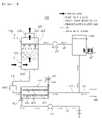
- FIG. 1 is a view illustrating a first embodiment of an exhaust gas treatment apparatus according to the present disclosure
- FIG. 2 is a view illustrating another example of a gas/liquid separation treatment liquid regeneration unit of a first embodiment of an exhaust gas treatment apparatus according to the present disclosure.
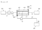
- FIG. 3 is a view illustrating an example of a gas treatment unit of a first embodiment of an exhaust gas treatment apparatus according to the present disclosure
- FIG. 4 is a view illustrating another example of a gas treatment unit of a first embodiment of an exhaust gas treatment apparatus according to the present disclosure.
- a first embodiment of an exhaust gas treatment apparatus may include a gas/liquid reactor 200, a treatment liquid supply tank 300, and a gas/liquid separation treatment liquid regeneration unit 400.
- Exhaust gas discharged from an exhaust gas discharge device such as an engine, a boiler, or the like may introduced into and flow in the gas/liquid reactor 200.
- the gas/liquid reactor 200 may contact the exhaust gas and a treatment liquid to absorb and remove an emission-regulated gas included in the exhaust gas by the treatment liquid.
- the emission-regulated gas may be, for example, sulfur oxide or carbon dioxide. Any kind of gases which emission to the atmosphere and should be regulated may be provided as the emission-regulated gas, such as nitrogen oxides.
- the gas/liquid reactor 200 may include a housing 210 and a treatment liquid spraying unit 220.
- the housing 210 may be connected to the exhaust gas discharge device.
- the housing 210 may be provided with an inlet 211, an outlet 212, and a drain 213.
- the inlet 211 may be provided on a lower side surface of the housing 210
- the outlet 212 may be provided on an upper surface of the housing 210
- the drain 213 may be provided on a lower surface of the housing 210.
- a portion of the housing 210 in which the inlet 211, the outlet 212, or the drain 213 is provided is not particularly limited.
- the inlet 211 may be connected to the exhaust gas discharge device. Therefore, the exhaust gas discharged from the exhaust gas discharge device may be introduced into the housing 210 through the inlet 211 as illustrated in FIG. 1 , and may flow in the housing 210.
- the treatment liquid may be sprayed into the housing 210 by the treatment liquid spraying unit 220, as illustrated in FIG. 1 . Therefore, the exhaust gas introducing into and flowing in the housing 210 may be in contact with the treatment liquid.
- the emission-regulated gas included in the exhaust gas such as sulfur oxide or carbon dioxide
- the emission-regulated gas may be absorbed by the treatment liquid, and may be removed from the exhaust gas.
- the exhaust gas from which the emission-regulated gas has been removed may be discharged through the outlet 212.
- the waste treatment liquid which may be a treatment liquid in which the emission-regulated gas is absorbed, may be drained through the drain 213.
- a packing 230 may be provided in the housing 210.
- the packing 230 may increase a contact area and a contact time between the exhaust gas and the treatment liquid. Therefore, treatment efficiency of the exhaust gas by the treatment liquid may be improved.
- the packing 230 may include a plurality of members having a plurality of holes formed therein. Instead of the packing 230, a configuration in which the contact area and the contact time between the exhaust gas and the treatment liquid increase, such as the packing 230, may be provided in the housing 210.
- the housing 210 may have a rectangular cross-section.
- the housing 210 may be installed in a funnel (not illustrated) of, for example, a ship (not illustrated).
- the funnel of the ship may have a rectangular cross-section.
- a dead area a space that cannot be used, may be minimized.
- the funnel may be extended, for example, in a direction facing a bow or a stern of the ship.
- the dead area may be minimized when installed in the funnel of the ship having a rectangular cross-section as described above, such that an expanded area of the funnel for installation of the housing 210 may be minimized. Therefore, the housing 210 may easily be installed in the funnel of the ship, time, materials, and the like for installation of the housing 210 in the funnel may be saved, and utilization of a space of the ship may be improved.
- the treatment liquid spraying unit 220 may spray the treatment liquid into the exhaust gas flowing in the housing 210.
- the treatment liquid spraying unit 220 may include a treatment liquid flow pipe 221 and a treatment liquid spraying nozzle 222.
- the treatment liquid flow pipe 221 may be connected to the treatment liquid supply tank 300.
- the treatment liquid flow pipe 221 may be connected to the treatment liquid supply tank 300 by a treatment liquid supply pipe LP, as illustrated in FIG. 1 .
- a treatment liquid supply pump PP may be provided in the treatment liquid supply pipe LP.
- the treatment liquid stored in the treatment liquid supply tank 300 may flow through the treatment liquid flow pipe 221.
- the treatment liquid flow pipe 221 may pass through one surface of the housing 210, and may be provided in the housing 210.
- the treatment liquid spraying nozzle 222 may be provided in a portion of the treatment liquid flow pipe 221 provided in the housing 210. Therefore, the treatment liquid flowing through the treatment liquid flow pipe 221 may be sprayed into the exhaust gas flowing in the housing 210 through the treatment liquid spraying nozzle 222, as illustrated in FIG. 1 .
- the treatment liquid supply tank 300 may supply the treatment liquid to the gas/liquid reactor 200.
- the treatment liquid may be stored in the treatment liquid supply tank 300.
- the treatment liquid stored in the treatment liquid supply tank 300 may be, for example, seawater, or an alkaline aqueous solution such as an aqueous sodium hydroxide solution or the like.
- the treatment liquid stored in the treatment liquid supply tank 300 is not particularly limited, and the treatment liquid may be any of the well-known things as long as it can be sprayed into the exhaust gas to be in contact with the exhaust gas and absorb the emission-regulated gas included in the exhaust gas, and it can be regenerated by separating the emission-regulated gas from it in the gas/liquid separation treatment liquid regeneration unit 400.
- One side of the treatment liquid supply pipe LP may be connected to the treatment liquid supply tank 300, as illustrated in FIG. 1 .
- the other side of the treatment liquid supply pipe LP may be connected to the treatment liquid flow pipe 221 of the treatment liquid spraying unit 220.
- the treatment liquid in the treatment liquid supply tank 300 may be supplied to the treatment liquid spraying unit 220 through the treatment liquid supply pipe LP.
- One side of a treatment liquid recovery pipe LR may be connected to the treatment liquid supply tank 300.
- the other side of the treatment liquid recovery pipe LR may be connected to the gas/liquid separation treatment liquid regeneration unit 400.
- the treatment liquid regenerated in the gas/liquid separation treatment liquid regeneration unit 400 may be supplied to and stored in the treatment liquid supply tank 300, through the treatment liquid recovery pipe LR, as illustrated in FIG. 1 .
- a treatment agent supply tank 600 may be connected to the treatment liquid recovery pipe LR by a treatment agent supply pipe LT. Therefore, a treatment agent stored in the treatment agent supply tank 600, for example, an alkali agent such as sodium hydroxide, may be supplied to the regenerated treatment liquid flowing in the treatment liquid recovery pipe LR through the treatment agent supply pipe LT.
- the treatment agent supply pipe LT may be connected to the treatment liquid supply tank 300, not the treatment liquid recovery pipe LR, as illustrated in FIG. 5 , to supply the treatment agent stored in the treatment agent supply tank 600 to the treatment liquid stored in the treatment liquid supply tank 300.
- a heat exchanger HE may be connected to the treatment liquid supply tank 300, as illustrated in FIG. 1 .
- the heat exchanger HE may heat exchange with the treatment liquid stored in the treatment liquid supply tank 300, to cool the treatment liquid to a temperature capable of relatively well absorbing the emission-regulated gas included in the exhaust gas.
- the treatment liquid may absorb the emission-regulated gas included in the exhaust gas in the gas/liquid reactor 200 to become a waste treatment liquid, and a temperature thereof may increase by the exhaust gas having a high temperature.
- a temperature of a regenerated treatment liquid may be also higher than a temperature of the treatment liquid before being sprayed into the gas/liquid reactor 200.
- a temperature of the treatment liquid stored in the treatment liquid supply tank 300 may increase, to reduce an absorption rate of the emission-regulated gas of the treatment liquid.
- an absorption rate of the emission-regulated gas of the treatment liquid may not be lowered.
- the gas/liquid separation treatment liquid regeneration unit 400 may separate the emission-regulated gas from the waste treatment liquid which is a treatment liquid having absorbed the emission-regulated gas and drained from the gas/liquid reactor 200, may regenerate the waste treatment liquid as a treatment liquid, and may supply the regenerated treatment liquid to the treatment liquid supply tank 300. In this manner, since the treatment liquid may be regenerated and reused, costs required to treat the exhaust gas may be reduced.
- one side of a waste treatment liquid drain pipe LD may be connected to the drain 213 of the gas/liquid reactor 200, and the other side of the waste treatment liquid drain pipe LD may be connected to the gas/liquid separation treatment liquid regeneration unit 400. Therefore, the waste treatment liquid drained through the drain 213 of the gas/liquid reactor 200 may flow to the gas/liquid separation treatment liquid regeneration unit 400 through the waste treatment liquid drain pipe LD.
- a booster pump PB may be provided in the waste treatment liquid drain pipe LD, as illustrated in FIG. 4 .
- the waste treatment liquid drain pipe LD may be provided with a filtration treatment unit WTS that filters and treats pollutants excluding the emission-regulated gas, included in the waste treatment liquid, as illustrated in FIG. 1 .
- the pollutants excluding the emission-regulated gas, included in the waste treatment liquid may include particulate materials, oil, or the like.
- the filtration treatment unit WTS may filter the pollutants excluding the emission-regulated gas included in the waste treatment liquid flowing to the gas/liquid separation treatment liquid regeneration unit 400 through the waste treatment liquid drain pipe LD. Therefore, for example, particulate materials, oil, or the like included in the waste treatment liquid may be filtered by the filtration treatment unit WTS, to minimize amounts of the pollutants included in the treatment liquid regenerated in the gas/liquid separation treatment liquid regeneration unit 400.
- the filtration treatment unit WTS may filter particulate material, oil, or the like from the waste treatment liquid using, for example, a filter (not illustrated), centrifugal force, or the like.
- a configuration in which the filtration treatment unit WTS filters particulate material, oil, or the like from the waste treatment liquid is not particularly limited, and any known configuration may be used.
- one side of the treatment liquid recovery pipe LR may be connected to the gas/liquid separation treatment liquid regeneration unit 400, and the other side of the treatment liquid recovery pipe LR may be connected to the treatment liquid supply tank 300. Therefore, the treatment liquid regenerated in the gas/liquid separation treatment liquid regeneration unit 400 may be supplied to the treatment liquid supply tank 300 through the treatment liquid recovery pipe LR, and may be reused as a treatment liquid.
- the gas/liquid separation treatment liquid regeneration unit 400 may include the gas/liquid separation membrane 420 passing a gas but not passing a liquid, and the gas/liquid separation membrane 420 may partition a liquid flow path 411 through which the waste treatment liquid flows and a gas flow path 412 through which the emission-regulated gas flows .
- the emission-regulated gas may pass through the gas/liquid separation membrane 420 of the present disclosure, but the waste treatment liquid may not pass through the gas/liquid separation membrane 420.
- a low partial pressure of the emission-regulated gas may be formed in the gas flow path 412, such that the emission-regulated gas absorbed in the waste treatment liquid flows through the liquid flow path 411 and passes through the gas/liquid separation membrane 420, and moves to the gas flow path 412 in which a low partial pressure of the emission-regulated gas is formed, to separate the emission-regulated gas and the treatment liquid.
- a low partial pressure of the emission-regulated gas may refer to a state in which a concentration of the emission-regulated gas is low.
- carbon dioxide of the emission-regulated gas is described as an example, a concentration of the carbon dioxide may be low in the gas flow path 412 and a low partial pressure of the carbon dioxide may be formed.
- the emission-regulated gas absorbed in the waste treatment liquid flows through the liquid flow path 411 and passes through the gas/liquid separation membrane 420, to move to the gas flow path 412 in which a low partial pressure of the emission-regulated gas is formed.
- a negative pressure may be applied to create a low partial pressure of the emission-regulated gas, or the emission-regulated gas may be diluted with sweeping air .
- the emission-regulated gas absorbed in the waste treatment liquid may flow through the liquid flow path 411, may pass through the gas/liquid separation membrane 420, and may move to the gas flow path in which a low partial pressure of the emission-regulated gas is formed, to easily separate the emission-regulated gas from the waste treatment liquid.
- the gas/liquid separation membrane 420 through which a gas can pass but a liquid cannot pass may be used, and a low partial pressure of the emission-regulated gas may be formed in the gas flow path 412 partitioned by the gas/liquid separation membrane 420, to separate the emission-regulated gas from the waste treatment liquid. Therefore, the waste treatment liquid may be regenerated as a treatment liquid in which the emission-regulated gas is not absorbed. In using such a method, since an amount of the treatment agent to be supplied to the regenerated treatment liquid may be reduced, costs required to regenerate the waste treatment liquid may be reduced. Therefore, costs required to treat the exhaust gas may be reduced.
- the exhaust gas treatment apparatus 100 may be easily installed in a place in which an installation space is limited, such as a ship.
- the gas/liquid separation treatment liquid regeneration unit 400 may be configured to include a separation unit body 410 as illustrated in FIG. 1 .
- An internal space of the separation unit body 410 may be divided into the liquid flow path 411 and the gas flow path 412 by the gas/liquid separation membrane 420.
- the waste treatment liquid drain pipe LD connected to the drain 213 of the gas/liquid reactor 200 may be connected to one side of the liquid flow path 411, and the other side of the liquid flow path 411 may be connected to the treatment liquid supply tank 300 by the liquid recovery pipe LR. Therefore, the waste treatment liquid drained through the drain 213 of the gas/liquid reactor 200 may be introduced into the liquid flow path 411 to flow through the liquid flow path 411. While flowing through the liquid flow path 411, the emission-regulated gas may be separated and the regenerated treatment liquid may be introduced into the treatment liquid recovery pipe LR and flow to the treatment liquid supply tank 300 through the treatment liquid recovery pipe LR.
- a gas recovery pipe LG provided with a vacuum pump PV may be connected to one side of the gas flow path 412, as illustrated in FIG. 1 . Therefore, when the vacuum pump PV is driven, a low partial pressure of the emission-regulated gas may be formed in the gas flow path 412.
- an air inlet pipe LA provided with a flow control valve VC may be connected to the other side of the gas flow path 412. Thereby, in a state in which the vacuum pump PV is driven, the flow control valve VC may be operated to control a flow rate of air flowing into the air inlet pipe LA, to adjust a low partial pressure of the emission-regulated gas formed in the gas flow path 412.
- the gas/liquid separation membrane 420 may be a hollow fiber membrane in which the gas flow path 412 may be formed, as illustrated in FIG. 1 . Therefore, an internal space of the separation unit body 410, other than the gas/liquid separation membrane 420, may form the liquid flow path 411.
- the gas/liquid separation membrane 420 may be a hollow fiber membrane in which the liquid flow path 411 may be formed, as illustrated in FIG. 2 . In this case, an internal space of the separation unit body 410, other than the gas/liquid separation membrane 420, may be the gas flow path 412.
- the gas/liquid separation membrane 420 is not particularly limited, and the gas/liquid separation membrane 420 may be any of the well-known things such as flat membranes as long as the emission-regulated gas can pass through it but the waste treatment liquid cannot pass through it, and it can partition the internal space of separation unit body 410 into the liquid flow path 411 through which the waste treatment liquid flows and the gas flow path 412 through which the emission-regulated gas flows.
- the treatment liquid sprayed into the exhaust gas by the treatment liquid spraying unit 220 may mainly remove the sulfur oxide included in the exhaust gas, from the exhaust gas. That is, the exhaust gas may be desulfurized by the treatment liquid in the gas/liquid reactor 200.
- the waste treatment liquid removing the sulfur oxide from the exhaust gas may include the sulfur oxide, and the gas/liquid separation treatment liquid regeneration unit 400 may separate the emission-regulated gas, which may be sulfur oxide such as sulfur dioxide or the like, from the waste treatment liquid.
- the treatment liquid sprayed into the exhaust gas by the treatment liquid spraying unit 220 may mainly remove carbon dioxide included in the exhaust gas, from the exhaust gas.
- the waste treatment liquid removing the carbon dioxide from the exhaust gas may include the carbon dioxide, and the gas/liquid separation treatment liquid regeneration unit 400 may separate the carbon dioxide, from the waste treatment liquid.
- the first embodiment of the exhaust gas treatment apparatus 100 may further include a gas treatment unit 500.
- the gas treatment unit 500 may treat the emission-regulated gas separated from the waste treatment liquid in the gas/liquid separation treatment liquid regeneration unit 400.
- the emission-regulated gas may be dissolved and treated in seawater in an eco-friendly ion state.
- the emission-regulated gas carbon dioxide may be dissolved and treated in seawater in a state of natural eco-friendly ionized substances such as carbonic acid, bicarbonate, carbonate, or the like, and sulfur oxide may be dissolved and treated in seawater in a state of natural eco-friendly ionized substances such as sulfuric acid, sulfate, or the like.
- the gas treatment unit 500 may include a seawater flow pipe 510 through which the seawater flows and to which a gas recovery pipe LG connected to the gas/liquid separation treatment liquid regeneration unit 400 is connected, as illustrated in FIG. 3 .
- the seawater flow pipe 510 may be, for example, a cooling water pipe, a ballast water pipe, a sea chest, or the like, provided in a ship.
- the seawater flow pipe 510 is not particularly limited, and any known pipe may be used as long as seawater flows therethrough.
- a portion of the seawater flow pipe 510 to which the gas return pipe LG is connected may be branched as a plurality of branched portions, as illustrated in FIG. 3 .
- the gas recovery pipe LG may be branched and connected to the branched portions of the seawater flow pipe 510, respectively.
- a pressure control device VCP may be provided in the seawater flow pipe 510. Thereby, a pressure of seawater flowing through the seawater flow pipe 510 may increase to easily dissolve the emission-regulated gas in seawater in an eco-friendly ion state.
- the gas treatment unit 500 may further include a microbubble generator 520 provided in the seawater flow pipe 510 to be connected to the gas recovery pipe LG, as illustrated in FIG. 3 .
- the emission-regulated gas may be mixed with seawater flowing through the seawater flow pipe 510 as microbubbles .
- a plurality of micropores 521 may be formed in the microbubble generator 520, such that the emission-regulated gas flowing through the gas recovery pipe LG passes through the micropores 521 to be mixed with the seawater flowing through the seawater flow pipe 510 as microbubbles.
- the emission-regulated gas may be better dissolved in the seawater in an eco-friendly ionic state.
- the gas treatment unit 500 may further include a gas mixer 530.
- the gas mixer 530 may be provided in a portion of the seawater flow pipe 510, next to the microbubble generator 520, in a flow direction of the seawater, as illustrated in FIG. 3 .
- bubbles of the emission-regulated gas generated in the microbubble generator 520 and supplied to the seawater flowing through the seawater flow pipe 510 may be mixed with the seawater.
- the gas mixer 530 may be provided to rotate a mixing member 531 having a screw shape and to mix the emission-regulated gas bubbles supplied to seawater of the seawater flow pipe 510 and the seawater. Therefore, the emission-regulated gas may be better dissolved in the seawater in an eco-friendly ionic state.
- the branched portions of the seawater flow pipe 510 may be again combined and connected to sea SEA, as illustrated in FIG. 3 . Therefore, seawater in which the emission-regulated gas is dissolved in an eco-friendly ionic state may be drained into the sea SEA. As illustrated in FIG. 3 , a water quality measurement sensor SP may be provided in a portion of the seawater flow pipe 510 for discharging the seawater in which the emission-regulated gas is dissolved in an environment-friendly ionic state, into the sea.
- the gas treatment unit 500 may dissolve and treat the emission-regulated gas in fresh water flowing through a fresh water flow pipe (not illustrated) in an eco-friendly ion state.
- the gas treatment unit 500 may store and treat the emission-regulated gas separated from the waste treatment liquid in the gas/liquid separation treatment liquid regeneration unit 400.
- a no-discharge condition in which no material should be discharged from a ship or the like may be required. Therefore, in a ship running such an area, the gas treatment unit 500 may store the emission-regulated gas separated from the waste treatment liquid in the gas/liquid separation treatment liquid regeneration unit 400. In this manner, the emission-regulated gas stored in the gas treatment unit 500 may be supplied to a place of use.
- a gas treatment unit 500 may include a gas storage tank 540 to which a gas recovery pipe LG is connected to store an emission-regulated gas.
- An emission-regulated gas separated from a waste treatment liquid in a gas/liquid separation treatment liquid regeneration unit 400 may be stored in the gas storage tank 540 through the gas recovery pipe LG.
- the emission-regulated gas may be cooled and compressed to liquefy the emission-regulated gas, to store the emission-regulated gas in a liquid state. In this manner, the emission-regulated gas stored in a liquid state in the gas storage tank 540 may be supplied to a place of use.
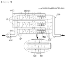
- FIG. 5 is a view illustrating a second embodiment of an exhaust gas treatment apparatus according to the present disclosure.
- a second embodiment of an exhaust gas treatment apparatus according to the present disclosure may be different from the first embodiment of the exhaust gas treatment apparatus according to the present disclosure described with reference to FIGS. 1 to 4 above, in view of the facts that sulfur oxide included in exhaust gas from a gas/liquid reactor 200 may be absorbed and removed by a first treatment liquid, and carbon dioxide included in exhaust gas from which the sulfur oxide is removed may be absorbed and removed by a second treatment liquid.
- a first removal region RR1 in which the exhaust gas and the first treatment liquid are in contact to remove the sulfur oxide, a second removal region RR2 in which the exhaust gas and the second treatment liquid are in contact to remove the carbon dioxide, and a connection region RC connecting the first removal region RR1 and the second removal region RR2 are provided in the gas/liquid reactor 200.
- sulfur oxide included in exhaust gas may be absorbed and removed by a first treatment liquid
- carbon dioxide included in the exhaust gas from which the sulfur oxide is removed may be absorbed and removed by a second treatment liquid.
- the sulfur oxide When a treatment liquid, for example an alkaline aqueous solution, is sprayed into exhaust gas containing both sulfur oxide and carbon dioxide, the sulfur oxide may be first removed from the exhaust gas. Therefore, in order to remove the carbon dioxide from the exhaust gas, the sulfur oxide included in the exhaust gas should be removed first. As described above, when the first treatment liquid absorbs and removes the sulfur oxide included in the exhaust gas, and the second treatment liquid absorbs and removes the carbon dioxide included in the exhaust gas from which the sulfur oxide are removed, all the sulfur oxide and the carbon dioxide may be removed from the exhaust gas. In addition, even when the exhaust gas includes a small amount of the sulfur oxide, since the sulfur oxide may be removed first, a removal rate of the carbon dioxide may be further improved.
- a treatment liquid for example an alkaline aqueous solution
- a first removal region RR1 in which the exhaust gas and the first treatment liquid are in contact to remove the sulfur oxide, a second removal region RR2 in which the exhaust gas and the second treatment liquid are in contact to remove the carbon dioxide, and a connection region RC connecting the first removal region RR1 and the second removal region RR2 may be provided in the gas/liquid reactor 200.
- a housing 210 of the gas/liquid reactor 200 may be divided into the first removal region RR1, the second removal region RR2, and the connection region RC by a plurality of partition walls WD, as illustrated in FIG. 5 .
- the plurality of partition walls WD may be provided in the housing 210 such that the exhaust gas flows from the bottom to the top in the first removal region RR1 and the second removal region RR2, and the exhaust gas flows from the top to the bottom in the connection region RC.
- two (2) partition walls WD may be provided in the housing 210, respectively, such that an internal space of the housing 210 may be divided into the first removal region RR1, the second removal region RR2, and the connection region RC.
- one partition wall WD may partition the internal space of the housing 210 into the first removal region RR1 and a portion of the connection region RC
- the other partition wall WD may partition the internal space of the housing 210 into the second removal region RR2 and remainder of the connection region RC.
- partition wall WD partitioning the first removal region RR1 and the portion of the connection region RC may have an upper end portion in the internal space of the housing 210 to be spaced apart from an upper end portion of the housing 210 in a predetermined distance, as illustrated in FIG. 5 .
- partition wall WD partitioning the second removal region RR2 and the remainder of the connection region RC may have a lower end portion in the internal space of the housing 210 to be spaced apart from a lower end portion of the housing 210 in a predetermined distance.
- an inlet 211 connected to an exhaust gas discharge device may be connected to the first removal region RR1, and an outlet 212 may be connected to the second removal region RR2.
- the housing 210 may be provided with a first drain 213' and a second drain 213", respectively, and the first drain 213' may be connected to the first removal region RR1 and the second drain 213" may be connected to the second removal region RR2.
- the exhaust gas may flow from the bottom to the top in both the first removal region RR1 and the second removal region RR2, to remove sulfur oxide or carbon dioxide, and the exhaust gas from which the sulfur oxide is removed in the first removal region RR1 may flow from the top to the bottom in the connection region RC, to be introduced into the second removal region RR2.
- a gas/liquid separation treatment liquid regeneration unit 400 may include a pretreatment configuration and a treatment liquid recovery configuration, connected to the gas/liquid separation treatment liquid regeneration unit 400 for regeneration of a waste treatment liquid, and a configuration connected to a gas recovery pipe for separating the carbon dioxide.
- the gas/liquid reactor 200 of the second embodiment of the exhaust gas treatment apparatus 100 may include a first treatment liquid spraying unit 220' and a second treatment liquid spraying unit 220", as illustrated in FIG. 5 .
- the first treatment liquid spraying unit 220' may spray a first treatment liquid into the exhaust gas flowing through the first removal region RR1 of the housing 210.
- the first treatment liquid spraying unit 220' may include a first treatment liquid flow pipe 221' and a first treatment liquid spraying nozzle 222', as illustrated in FIG. 5 .
- the first treatment liquid flow pipe 221' may pass through one surface of the housing 210, and may be provided in the first removal region RR1.
- the first treatment liquid spraying nozzle 222' may be provided in a portion of the first treatment liquid flow pipe 221' provided in the first removal region RR1.
- the first treatment liquid spraying unit 220' may be provided as a plurality of first treatment liquid spraying units 220'.
- the plurality of first treatment liquid spraying units 220' may be arranged vertically at predetermined intervals.
- a first treatment liquid spraying unit 220' on the bottom may perform pre-treatment of removing a portion of the sulfur oxide from the exhaust gas while cooling a temperature of the exhaust gas by the first treatment liquid to facilitate removal of the sulfur oxide and the carbon dioxide.
- a remaining portion of the first treatment liquid spraying unit 220' may perform post-treatment to remove residual portion of the sulfur oxide from the exhaust gas.
- the number of the first treatment liquid spraying units 220' is not particularly limited, and any number may be used.
- the first treatment liquid may be seawater.
- a first treatment liquid supply pipe LP' connected to sea SEA may be connected to the first treatment liquid flow pipe 221' of the first treatment liquid spraying unit 220'.
- a first treatment liquid supply pump PP' may be provided in the first treatment liquid supply pipe LP'.
- a first waste treatment liquid drain pipe LD' connected to the sea SEA may be connected to the first drain 213' connected to the first removal region RR1 of the housing 210.
- seawater may flow through the first treatment liquid flow pipe 221' of the first treatment liquid spraying unit 220' as the first treatment liquid, to be sprayed into the exhaust gas flowing through the first removal region RR1 of the housing 210, by the first treatment liquid spraying nozzle 222' .
- a first waste treatment liquid which may be seawater sprayed into the first removal region RR1 of the housing 210 and in which the sulfur oxide is absorbed from the exhaust gas, may be drained to the sea SEA through the first waste treatment liquid drain pipe LD'.
- a water treatment unit (not illustrated) may be provided in the first waste treatment liquid drain pipe LD' , to water-treat the first waste treatment liquid, which may be seawater in which the sulfur oxide is absorbed from the exhaust gas, and then discharge the water-treated first waste treatment liquid to the sea SEA.
- the second treatment liquid spraying unit 220" may spray a second treatment liquid into the exhaust gas flowing through the second removal region RR2 of the housing 210.
- the second treatment liquid spraying unit 220" may include a second treatment liquid flow pipe 221" and a second treatment liquid spraying nozzle 222", as illustrated in FIG. 5 .
- the second treatment liquid flow pipe 221" may pass through the other surface of the housing 210 and be provided in the second removal region RR2.
- the second treatment liquid spraying nozzle 222" may be provided in a portion of the second treatment liquid flow pipe 221" provided in the second removal region RR2.
- the second treatment liquid may be supplied to the gas/liquid reactor 200.
- the second treatment liquid may be stored in the treatment liquid supply tank 300, and a second treatment liquid supply pipe LP" connected to the treatment liquid supply tank 300 may be connected to the treatment liquid flow pipe 221" of the second treatment liquid spraying unit 220".
- a second treatment liquid supply pump PP" may be provided in the second treatment liquid supply pipe LP".
- the second treatment liquid supply pump PP" When the second treatment liquid supply pump PP" is driven, the second treatment liquid stored in the treatment liquid supply tank 300 may flow through the second treatment liquid flow pipe 221" of the second treatment liquid spraying unit 220", to be sprayed into the exhaust gas flowing through the second removal region RR2 of the housing 210 by the second treatment liquid spraying nozzle 222".
- the second treatment liquid may be an alkaline aqueous solution such as an aqueous sodium hydroxide solution or the like.
- the gas/liquid separation treatment liquid regeneration unit 400 of the second embodiment of the exhaust gas treatment apparatus 100 may separate the carbon dioxide from a second waste treatment liquid drained from the gas/liquid reactor 200, which may be a second treatment liquid in which the carbon dioxide is absorbed, may regenerate the second waste treatment liquid as a second treatment liquid, and may supply the regenerated second treatment liquid to the treatment liquid supply tank 300.
- a second waste treatment liquid drain pipe LD" connected to the gas/liquid reactor 200 may be connected to one side of a liquid flow path 411 of the gas/liquid separation treatment liquid regeneration unit 400.
- the second waste treatment liquid drain pipe LD" may be connected to the second drain 213" connected to the second removal region RR2 of the gas/liquid reactor 200, and the second waste treatment liquid drain pipe LD" may be connected to the one side of the liquid flow path 411 of the gas/liquid separation treatment liquid regeneration unit 400.
- the other side of the liquid flow path 411 may be connected to the treatment liquid supply tank 300 by a treatment liquid recovery pipe LR.
- the carbon dioxide may be separated from the second waste treatment liquid, and the second waste liquid may be regenerated as a second treatment liquid.
- the regenerated second treatment liquid may be supplied to the treatment liquid supply tank 300 through the treatment liquid recovery pipe LR.
- the carbon dioxide separated from the second waste treatment liquid flowing through the liquid flow path 411 of the gas/liquid separation treatment liquid regeneration unit 400 and moved to a gas flow path 412 may flow to and be treated by the gas treatment unit 500 through a gas recovery pipe LG connected to the gas flow path 412.
- FIG. 6 is a view illustrating a third embodiment of an exhaust gas treatment apparatus according to the present disclosure.
- a third embodiment of an exhaust gas treatment apparatus according to the present disclosure may be different from the second embodiment of the exhaust gas treatment apparatus according to the present disclosure described with reference to FIG. 5 above, in view of the facts that a treatment liquid supply tank 300 may supply a first treatment liquid and a second treatment liquid to a gas/liquid reactor 200, respectively, and a first gas/liquid separation treatment liquid regeneration unit 400' for regenerating a first waste treatment liquid as the first treatment liquid, and a second gas/liquid separation treatment liquid regeneration unit 400" for regenerating a second waste treatment liquid as the second treatment liquid may be included.
- a treatment liquid supply tank 300 of the third embodiment of the exhaust gas treatment apparatus 100 according to the present disclosure may supply a first treatment liquid and a second treatment liquid to a gas/liquid reactor 200, respectively.
- an internal space of the treatment liquid supply tank 300 may be partitioned into a first storage region SS1 in which the first treatment liquid is stored, and a second storage region SS2 in which the second treatment liquid is stored, by a partition wall WD, as illustrated in FIG. 6 .
- first storage region SS1 may be connected to a first treatment liquid spraying unit 220' of the gas/liquid reactor 200 by a first treatment liquid supply pipe LP'
- second storage region SS2 may be connected to a second treatment liquid spraying unit 220" of the gas/liquid reactor 200 by a second treatment liquid supply pipe LP".
- the first treatment liquid in the first storage region SS1 may be supplied to the first treatment liquid spraying unit 220' through the first treatment liquid supply pipe LP'.
- the first treatment liquid supplied to the first treatment liquid spraying unit 220' may be sprayed into the exhaust gas flowing through a first removal region RR1 of the gas/liquid reactor 200.
- the second treatment liquid in the second storage region SS2 may be supplied to the second treatment liquid spraying unit 220" through the second treatment liquid supply pipe LP".
- the second treatment liquid supplied to the second treatment liquid spraying unit 220" may be sprayed into the exhaust gas flowing through a second removal region RR2 of the gas/liquid reactor 200.
- the first treatment liquid spraying unit 220' may be provided as a plurality of first treatment liquid spraying units 220' , and a packing 230 may be provided in a portion of the first removal region RR1 between the plurality of first treatment liquid spraying units 220' .
- a packing 230 may be provided in a portion of the first removal region RR1 between the two (2) first treatment liquid spraying units 220' .
- a first gas/liquid separation treatment liquid regeneration unit 400' may separate sulfur oxide from a first waste treatment liquid, which may be the first treatment liquid in which the sulfur oxide is absorbed, drained from the gas/liquid reactor 200, to regenerate the first waste treatment liquid as a first treatment liquid, and may supply the regenerated first treatment liquid to the treatment liquid supply tank 300.
- a first gas/liquid separation membrane 420' through which the sulfur oxide can pass but the first waste treatment liquid cannot pass may partition a first liquid flow path 411' through which the first waste treatment liquid flows and a first gas flow path 412' through which the sulfur oxide flows.
- a low partial pressure of sulfur oxide may be formed in the first gas flow path 412' , such that the sulfur oxide included in the first waste treatment liquid of the first liquid flow path 411' may move to the first gas flow path 412' by passing through the first gas/liquid separation membrane 420'.
- the first gas/liquid separation treatment liquid regeneration unit 400' may further include a first separation unit body 410' of which an internal space is partitioned into the first liquid flow path 411' and the first gas flow path 412' by the first gas/liquid separation membrane 420' .
- a first waste treatment liquid drain pipe LD' connected to a first drain 213' of the gas/liquid reactor 200 may be connected to one side of the first liquid flow path 411', and the other side of the first liquid flow path 411' may be connected to the first storage region SS1 of the treatment liquid supply tank 300 by a first treatment liquid recovery pipe LR'.
- a first gas recovery pipe LG' provided with a vacuum pump PV may be connected to one side of the first gas flow path 412', such that a low partial pressure of the sulfur oxide may be formed in the first gas flow path 412'.
- a first air inlet pipe LA' provided with a flow control valve VC may be connected to the other side of the first gas flow path 412', to adjust a partial pressure of the sulfur oxide formed in the first gas flow path 412'.
- the first gas/liquid separation membrane 420' may be a hollow fiber membrane in which the first gas flow path 412' or the first liquid flow path 411' is formed.
- a second gas/liquid separation treatment liquid regeneration unit 400" may separate carbon dioxide from a second waste treatment liquid, which may be the second treatment liquid in which the carbon dioxide is absorbed, drained from the gas/liquid reactor 200, to regenerate the second waste treatment liquid as a second treatment liquid, and may supply the regenerated second treatment liquid to the treatment liquid supply tank 300.
- a second gas/liquid separation membrane 420" through which the carbon dioxide can pass but the second waste treatment liquid cannot pass may partition a second liquid flow 411" through which the second waste treatment liquid flows and the second gas flow path 412" through which the carbon dioxide flows.
- a low partial pressure of carbon dioxide may be formed in the second gas flow path 412", such that the carbon dioxide included in the second waste treatment liquid of the second liquid flow path 411" may move to the second gas flow path 412" by passing through the second gas/liquid separation membrane 420".
- the second gas/liquid separation treatment liquid regeneration unit 400" may further include a second separation unit body 410" of which an internal space is partitioned into the second liquid flow path 411" and the second gas flow path 412" by the second gas/liquid separation membrane 420".
- a second waste treatment liquid drain pipe LD" connected to a second drain 213" of the gas/liquid reactor 200 may be connected to one side of the second liquid flow path 411", and the other side of the second liquid flow path 411" may be connected to the second storage region SS2 of the treatment liquid supply tank 300 by a second treatment liquid recovery pipe LR".
- a second gas recovery pipe LG" provided with a vacuum pump PV may be connected to one side of the second gas flow path 412", such that a low partial pressure of the carbon dioxide may be formed in the second gas flow path 412".
- a second air inlet pipe LA" provided with a flow control valve VC may be connected to the other side of the second gas flow path 412", to adjust a partial pressure of the carbon dioxide formed in the second gas flow path 412".
- the second gas/liquid separation membrane 420" may be a hollow fiber membrane in which the second gas flow path 412" or the second liquid flow path 411" is formed.
- the first treatment liquid and the second treatment liquid may be an aqueous alkaline solution such as an aqueous sodium hydroxide solution or the like.
- an alkali agent such as sodium hydroxide or the like may be stored in a treatment agent supply tank 600, and the treatment agent supply tank 600 may be connected to the first storage region SS1 and the second storage region SS2 of the treatment liquid supply tank 300, respectively, such that the alkali agent may be respectively supplied as a treatment agent.
- the first treatment liquid and the second treatment liquid may be different.
- each of the first gas recovery pipe LG' and the second gas recovery pipe LG" may be connected to a gas treatment unit 500.
- FIG. 7 is a view illustrating a fourth embodiment of an exhaust gas treatment apparatus according to the present disclosure.
- a fourth embodiment of an exhaust gas treatment apparatus according to the present disclosure may be different from the second and third embodiments of the exhaust gas treatment apparatus according to the present disclosure described with reference to FIGS. 5 and 6 above, in view of the facts that a cross-section of a housing 210 of a gas/liquid reactor 200 is circular or elliptical.
- a cross-section of a housing 210 of a gas/liquid reactor 200 may be circular or elliptical. Therefore, the housing 210 may be a cylinder or an elliptical cylinder, as illustrated in FIG. 7 .
- a first removal region RR1 may be located on an outermost side in a radial direction inside the housing 210, a connection region RC may be located on inside of the first removal region RR1, and a second removal region RR2 may be located on inside of the connection region RC.
- cross-sections of the first removal region RR1 and the connection region RC may be annular, and a cross-section of the second removal region RR2 may be circular or elliptical. Therefore, since exhaust gas may flow smoothly but not flow biased in one direction, treatment of the exhaust gas may be performed more smoothly.
- a plurality of partition walls WD which may be cylindrical or elliptical, may be provided in the housing 210 to partition an internal space of the housing 210 into the first removal region RR1, the connection region RC, and the second removal region RR2.
- two (2) partition walls WD which may be cylindrical or elliptical, may be provided in the housing 210 to partition an internal space of the housing 210 into the first removal region RR1, the connection region RC, and the second removal region RR2.
- the plurality of partition walls WD may be provided in the housing 210 such that the exhaust gas flows from the bottom to the top in the first removal region RR1 and the second removal region RR2, and the exhaust gas flows from the top to the bottom in the connection region RC.
- the exhaust gas discharged from the exhaust gas discharge device may be first introduced into the first removal region RR1 formed on the outermost side in the radial direction in the housing 210 and connected to an inlet 211, through the inlet 211.
- Sulfur oxide may be removed by a first treatment liquid sprayed into the first removal region RR1 while the exhaust gas introduced into the first removal region RR1 flows through the first removal region RR1.
- the exhaust gas from which the sulfur oxide is removed may flow into the second removal region RR2 inside of the connection region RC through the connection region RC inside of the first removal region RR1.
- Carbon dioxide may be removed while the exhaust gas introduced into the second removal region RR2 flows through the second removal region RR2.
- the exhaust gas from which the carbon dioxide is removed may be discharged through an outlet 212 connected to the second removal region RR2.
- a waste treatment liquid may be regenerated by a gas/liquid separation treatment liquid regeneration unit separating an emission-regulated gas from the waste treatment liquid which has treated exhaust gas, a regeneration rate of a waste treatment liquid which has treated exhaust gas may be increased, costs for treating exhaust gas in an exhaust gas treatment apparatus may be reduced, a size of an exhaust gas treatment apparatus may be reduced, and an emission-regulated gas may be separated from a waste treatment liquid gas in which the emission-regulated gas included in the exhaust gas is absorbed, and the separated emission-regulated gas may be treated by dissolving the emission-regulated gas in seawater in an eco-friendly ion state.
- the exhaust gas treatment apparatus described above may not be limitedly applicable to the configurations of the above-described embodiments, but the embodiments may be configured by selectively combining all or portion of each of the embodiments such that various modifications are made.
Landscapes
- Engineering & Computer Science (AREA)
- Chemical & Material Sciences (AREA)
- Combustion & Propulsion (AREA)
- Mechanical Engineering (AREA)
- General Engineering & Computer Science (AREA)
- Ocean & Marine Engineering (AREA)
- Treating Waste Gases (AREA)
- Gas Separation By Absorption (AREA)
- Separation Using Semi-Permeable Membranes (AREA)
Applications Claiming Priority (4)
| Application Number | Priority Date | Filing Date | Title |
|---|---|---|---|
| KR20190121672 | 2019-10-01 | ||
| KR1020200036753A KR102299077B1 (ko) | 2019-10-01 | 2020-03-26 | 배기가스 처리장치 |
| KR1020200036757A KR102339076B1 (ko) | 2019-10-01 | 2020-03-26 | 배기가스 처리장치 |
| PCT/KR2020/013230 WO2021066461A2 (fr) | 2019-10-01 | 2020-09-28 | Appareil de traitement de gaz d'échappement |
Publications (4)
| Publication Number | Publication Date |
|---|---|
| EP4033077A2 true EP4033077A2 (fr) | 2022-07-27 |
| EP4033077A4 EP4033077A4 (fr) | 2023-02-22 |
| EP4033077B1 EP4033077B1 (fr) | 2024-08-07 |
| EP4033077C0 EP4033077C0 (fr) | 2024-08-07 |
Family
ID=75336610
Family Applications (1)
| Application Number | Title | Priority Date | Filing Date |
|---|---|---|---|
| EP20872782.6A Active EP4033077B1 (fr) | 2019-10-01 | 2020-09-28 | Dispositif de traitement de gaz d'échappement |
Country Status (5)
| Country | Link |
|---|---|
| US (1) | US11788449B2 (fr) |
| EP (1) | EP4033077B1 (fr) |
| JP (1) | JP7413517B2 (fr) |
| CN (1) | CN114502823B (fr) |
| WO (1) | WO2021066461A2 (fr) |
Families Citing this family (4)
| Publication number | Priority date | Publication date | Assignee | Title |
|---|---|---|---|---|
| DE102021210372B3 (de) * | 2021-09-17 | 2023-01-26 | Rolls-Royce Solutions GmbH | Mischvorrichtung zur Durchmischung eines Abgasstroms mit einem Reaktionsmittel und Brennkraftmaschine mit einer solchen Mischvorrichtung |
| KR102635364B1 (ko) * | 2023-07-12 | 2024-02-08 | 국방과학연구소 | 이동형 화학 작용제 중화 장치 및 그 동작 방법 |
| SE547692C2 (en) * | 2024-02-13 | 2025-11-11 | Grimaldi Dev Ab | A system and method for separating a gas component from a gas mixture |
| CN119034437B (zh) * | 2024-09-25 | 2025-11-18 | 中国船舶集团有限公司第七一一研究所 | 一种处理装置及方法 |
Family Cites Families (24)
| Publication number | Priority date | Publication date | Assignee | Title |
|---|---|---|---|---|
| JPH0699018A (ja) * | 1991-02-08 | 1994-04-12 | Mitsubishi Heavy Ind Ltd | 膜式極性ガス分離装置 |
| JP4357882B2 (ja) | 2003-06-12 | 2009-11-04 | 正明 寺本 | ガス分離方法およびその装置 |
| JP4847118B2 (ja) | 2005-06-27 | 2011-12-28 | システム エンジ サービス株式会社 | 希薄な揮発性炭化水素を含む大量の排ガス浄化方法 |
| JP5023512B2 (ja) * | 2006-02-27 | 2012-09-12 | 三菱マテリアル株式会社 | ガスの分離回収方法及びその装置 |
| JP4486606B2 (ja) | 2006-03-24 | 2010-06-23 | 石油コンビナート高度統合運営技術研究組合 | 二酸化炭素ガス分離装置及び二酸化炭素ガス分離方法 |
| JP2008104953A (ja) | 2006-10-25 | 2008-05-08 | Research Institute Of Innovative Technology For The Earth | ガス分離方法及びガス分離装置 |
| US20090148370A1 (en) * | 2007-12-06 | 2009-06-11 | Spencer Iii Herbert W | Process to produce ammonia from urea |
| JP5070100B2 (ja) | 2008-03-25 | 2012-11-07 | 千代田化工建設株式会社 | 脱硫脱炭装置 |
| JP2010005509A (ja) | 2008-06-25 | 2010-01-14 | Toshiba Corp | 二酸化炭素分離装置及びその方法 |
| US8007570B2 (en) * | 2009-03-11 | 2011-08-30 | General Electric Company | Systems, methods, and apparatus for capturing CO2 using a solvent |
| JP5693368B2 (ja) | 2011-05-13 | 2015-04-01 | 日立造船株式会社 | 二酸化炭素回収方法における二酸化炭素吸収液の再生方法 |
| KR101722232B1 (ko) | 2011-05-19 | 2017-04-03 | 현대중공업 주식회사 | 선박 엔진의 배기가스 정화장치 |
| JP5929780B2 (ja) | 2013-02-18 | 2016-06-08 | 株式会社デンソー | エンジン湿式後処理装置用の気液分離装置 |
| US20150375169A1 (en) | 2013-06-14 | 2015-12-31 | Ionada Incorporated | Membrane-based exhaust gas scrubbing method and system |
| FI126920B (fi) * | 2013-12-11 | 2017-08-15 | Langh Patents Oy Ab | Pakokaasupesuri ja laiva, jossa pakokaasupesuri |
| DE102013225957A1 (de) * | 2013-12-13 | 2015-06-18 | BSH Hausgeräte GmbH | Beleuchtung mit einem Lichtleiter und Haushaltskältegerät mit einer solchen Beleuchtung |
| KR101574660B1 (ko) * | 2014-03-31 | 2015-12-07 | (주) 테크윈 | 소수성막을 이용한 기액 분리기 |
| KR101512459B1 (ko) | 2014-03-31 | 2015-04-16 | 충남대학교산학협력단 | 고성능 기액접촉모듈을 이용한 다기능 대기오염처리장치 |
| KR101647462B1 (ko) | 2014-07-21 | 2016-08-10 | 대우조선해양 주식회사 | 해수 순환 시스템 및 방법 |
| KR101777372B1 (ko) * | 2015-04-03 | 2017-09-13 | 한국에너지기술연구원 | 선박 배기가스로부터 탄산염 광물의 제조 및 산성 가스 제거방법, 및 이를 위한 장치 |
| DE112017001147B4 (de) | 2016-03-04 | 2022-11-24 | Asahi Kasei Kabushiki Kaisha | Modul für Gastrennung, Gastrennungsverfahren und Verwendung des Gastrennungsverfahrens zur Herstellung eines Olefingases |
| JP2017200682A (ja) | 2016-05-06 | 2017-11-09 | 大阪ガスエンジニアリング株式会社 | 燃料ガスの処理方法及び燃料ガスの処理装置 |
| KR102128754B1 (ko) * | 2017-11-06 | 2020-07-01 | 한국에너지기술연구원 | 중공사 분리막을 이용한 선박용 배기가스 탈황 처리시스템 및 처리방법 |
| JP2019205966A (ja) | 2018-05-29 | 2019-12-05 | イーセップ株式会社 | Co2膜分離方法 |
-
2020
- 2020-09-28 CN CN202080069184.0A patent/CN114502823B/zh active Active
- 2020-09-28 WO PCT/KR2020/013230 patent/WO2021066461A2/fr not_active Ceased
- 2020-09-28 JP JP2022520160A patent/JP7413517B2/ja active Active
- 2020-09-28 EP EP20872782.6A patent/EP4033077B1/fr active Active
- 2020-09-28 US US17/765,632 patent/US11788449B2/en active Active
Also Published As
| Publication number | Publication date |
|---|---|
| EP4033077A4 (fr) | 2023-02-22 |
| JP2023506680A (ja) | 2023-02-20 |
| US20220372902A1 (en) | 2022-11-24 |
| US11788449B2 (en) | 2023-10-17 |
| WO2021066461A3 (fr) | 2021-07-29 |
| EP4033077B1 (fr) | 2024-08-07 |
| CN114502823B (zh) | 2025-01-07 |
| JP7413517B2 (ja) | 2024-01-15 |
| CN114502823A (zh) | 2022-05-13 |
| EP4033077C0 (fr) | 2024-08-07 |
| WO2021066461A2 (fr) | 2021-04-08 |
Similar Documents
| Publication | Publication Date | Title |
|---|---|---|
| KR102611937B1 (ko) | 배기가스 처리장치 | |
| US11788449B2 (en) | Exhaust gas treatment apparatus | |
| KR102378554B1 (ko) | 선박용 배기가스 처리장치 및 이를 포함하는 선박 | |
| KR20240078461A (ko) | 선박의 온실가스 배출 저감장치 및 이를 구비한 선박 | |
| JP7572547B2 (ja) | 船舶の温室効果ガス排出低減装置及び同装置を具備した船舶 | |
| KR102856016B1 (ko) | 선박의 온실가스 배출 저감장치 | |
| KR102728118B1 (ko) | 배기가스 처리장치 | |
| EP4230849A1 (fr) | Dispositif permettant de réduire les émissions de gaz à effet de serre de navires et navire le comprenant | |
| KR20220008550A (ko) | 선박 | |
| KR102847756B1 (ko) | 선박의 온실가스 배출저감 장치 및 동 장치를 구비한 선박 또는 해양구조물 | |
| KR102847757B1 (ko) | 선박의 온실가스 배출저감 장치 및 동 장치를 구비한 선박 또는 해양구조물 | |
| KR102847755B1 (ko) | 선박의 온실가스 배출저감 장치 및 동 장치를 구비한 선박 또는 해양구조물 | |
| KR102729094B1 (ko) | 선박의 온실가스 배출 저감장치 및 이를 구비한 선박 | |
| KR20240028318A (ko) | 배기가스 처리 시스템 및 이를 포함하는 선박 | |
| KR20240078463A (ko) | 선박의 온실가스 배출 저감장치 및 이를 구비한 선박 | |
| KR20240078462A (ko) | 선박의 온실가스 배출 저감장치 및 이를 구비한 선박 | |
| KR20240076575A (ko) | 선박의 온실가스 배출 저감장치 및 이를 구비한 선박 | |
| KR20240075031A (ko) | 선박의 온실가스 배출 저감장치 및 이를 구비한 선박 | |
| KR20240090062A (ko) | 선박의 온실가스 배출 저감장치 및 이를 구비한 선박 또는 해양 구조물 | |
| CN119677940A (zh) | 船舶的温室气体减排装置及具备其的船舶或海洋结构物 | |
| KR20240076428A (ko) | 선박의 온실가스 배출 저감장치 및 이를 구비한 선박 | |
| KR20240076429A (ko) | 선박의 온실가스 배출 저감장치 및 이를 구비한 선박 | |
| KR20240076439A (ko) | 선박의 온실가스 배출 저감장치 및 이를 구비한 선박 | |
| KR20240076438A (ko) | 선박의 온실가스 배출 저감장치 및 이를 구비한 선박 | |
| KR20240076442A (ko) | 선박의 온실가스 배출 저감장치 및 이를 구비한 선박 |
Legal Events
| Date | Code | Title | Description |
|---|---|---|---|
| STAA | Information on the status of an ep patent application or granted ep patent |
Free format text: STATUS: THE INTERNATIONAL PUBLICATION HAS BEEN MADE |
|
| PUAI | Public reference made under article 153(3) epc to a published international application that has entered the european phase |
Free format text: ORIGINAL CODE: 0009012 |
|
| STAA | Information on the status of an ep patent application or granted ep patent |
Free format text: STATUS: REQUEST FOR EXAMINATION WAS MADE |
|
| 17P | Request for examination filed |
Effective date: 20220420 |
|
| AK | Designated contracting states |
Kind code of ref document: A2 Designated state(s): AL AT BE BG CH CY CZ DE DK EE ES FI FR GB GR HR HU IE IS IT LI LT LU LV MC MK MT NL NO PL PT RO RS SE SI SK SM TR |
|
| DAV | Request for validation of the european patent (deleted) | ||
| DAX | Request for extension of the european patent (deleted) | ||
| A4 | Supplementary search report drawn up and despatched |
Effective date: 20230123 |
|
| RIC1 | Information provided on ipc code assigned before grant |
Ipc: F01N 13/00 20100101ALI20230117BHEP Ipc: F01N 3/08 20060101ALI20230117BHEP Ipc: F01N 3/04 20060101AFI20230117BHEP |
|
| GRAP | Despatch of communication of intention to grant a patent |
Free format text: ORIGINAL CODE: EPIDOSNIGR1 |
|
| STAA | Information on the status of an ep patent application or granted ep patent |
Free format text: STATUS: GRANT OF PATENT IS INTENDED |
|
| RIC1 | Information provided on ipc code assigned before grant |
Ipc: F01N 13/00 20100101ALI20240221BHEP Ipc: F01N 3/08 20060101ALI20240221BHEP Ipc: F01N 3/04 20060101AFI20240221BHEP |
|
| INTG | Intention to grant announced |
Effective date: 20240312 |
|
| GRAS | Grant fee paid |
Free format text: ORIGINAL CODE: EPIDOSNIGR3 |
|
| GRAA | (expected) grant |
Free format text: ORIGINAL CODE: 0009210 |
|
| STAA | Information on the status of an ep patent application or granted ep patent |
Free format text: STATUS: THE PATENT HAS BEEN GRANTED |
|
| AK | Designated contracting states |
Kind code of ref document: B1 Designated state(s): AL AT BE BG CH CY CZ DE DK EE ES FI FR GB GR HR HU IE IS IT LI LT LU LV MC MK MT NL NO PL PT RO RS SE SI SK SM TR |
|
| REG | Reference to a national code |
Ref country code: GB Ref legal event code: FG4D |
|
| REG | Reference to a national code |
Ref country code: CH Ref legal event code: EP |
|
| REG | Reference to a national code |
Ref country code: IE Ref legal event code: FG4D |
|
| REG | Reference to a national code |
Ref country code: DE Ref legal event code: R096 Ref document number: 602020035530 Country of ref document: DE |
|
| U01 | Request for unitary effect filed |
Effective date: 20240905 |
|
| U07 | Unitary effect registered |
Designated state(s): AT BE BG DE DK EE FI FR IT LT LU LV MT NL PT RO SE SI Effective date: 20240919 |
|
| U20 | Renewal fee for the european patent with unitary effect paid |
Year of fee payment: 5 Effective date: 20240927 |
|
| PG25 | Lapsed in a contracting state [announced via postgrant information from national office to epo] |
Ref country code: PL Free format text: LAPSE BECAUSE OF FAILURE TO SUBMIT A TRANSLATION OF THE DESCRIPTION OR TO PAY THE FEE WITHIN THE PRESCRIBED TIME-LIMIT Effective date: 20240807 Ref country code: GR Free format text: LAPSE BECAUSE OF FAILURE TO SUBMIT A TRANSLATION OF THE DESCRIPTION OR TO PAY THE FEE WITHIN THE PRESCRIBED TIME-LIMIT Effective date: 20241108 |
|
| PG25 | Lapsed in a contracting state [announced via postgrant information from national office to epo] |
Ref country code: IS Free format text: LAPSE BECAUSE OF FAILURE TO SUBMIT A TRANSLATION OF THE DESCRIPTION OR TO PAY THE FEE WITHIN THE PRESCRIBED TIME-LIMIT Effective date: 20241207 |
|
| PG25 | Lapsed in a contracting state [announced via postgrant information from national office to epo] |
Ref country code: HR Free format text: LAPSE BECAUSE OF FAILURE TO SUBMIT A TRANSLATION OF THE DESCRIPTION OR TO PAY THE FEE WITHIN THE PRESCRIBED TIME-LIMIT Effective date: 20240807 |
|
| PG25 | Lapsed in a contracting state [announced via postgrant information from national office to epo] |
Ref country code: RS Free format text: LAPSE BECAUSE OF FAILURE TO SUBMIT A TRANSLATION OF THE DESCRIPTION OR TO PAY THE FEE WITHIN THE PRESCRIBED TIME-LIMIT Effective date: 20241107 Ref country code: ES Free format text: LAPSE BECAUSE OF FAILURE TO SUBMIT A TRANSLATION OF THE DESCRIPTION OR TO PAY THE FEE WITHIN THE PRESCRIBED TIME-LIMIT Effective date: 20240807 |
|
| PG25 | Lapsed in a contracting state [announced via postgrant information from national office to epo] |
Ref country code: RS Free format text: LAPSE BECAUSE OF FAILURE TO SUBMIT A TRANSLATION OF THE DESCRIPTION OR TO PAY THE FEE WITHIN THE PRESCRIBED TIME-LIMIT Effective date: 20241107 Ref country code: PL Free format text: LAPSE BECAUSE OF FAILURE TO SUBMIT A TRANSLATION OF THE DESCRIPTION OR TO PAY THE FEE WITHIN THE PRESCRIBED TIME-LIMIT Effective date: 20240807 Ref country code: IS Free format text: LAPSE BECAUSE OF FAILURE TO SUBMIT A TRANSLATION OF THE DESCRIPTION OR TO PAY THE FEE WITHIN THE PRESCRIBED TIME-LIMIT Effective date: 20241207 Ref country code: HR Free format text: LAPSE BECAUSE OF FAILURE TO SUBMIT A TRANSLATION OF THE DESCRIPTION OR TO PAY THE FEE WITHIN THE PRESCRIBED TIME-LIMIT Effective date: 20240807 Ref country code: GR Free format text: LAPSE BECAUSE OF FAILURE TO SUBMIT A TRANSLATION OF THE DESCRIPTION OR TO PAY THE FEE WITHIN THE PRESCRIBED TIME-LIMIT Effective date: 20241108 Ref country code: ES Free format text: LAPSE BECAUSE OF FAILURE TO SUBMIT A TRANSLATION OF THE DESCRIPTION OR TO PAY THE FEE WITHIN THE PRESCRIBED TIME-LIMIT Effective date: 20240807 |
|
| PG25 | Lapsed in a contracting state [announced via postgrant information from national office to epo] |
Ref country code: SM Free format text: LAPSE BECAUSE OF FAILURE TO SUBMIT A TRANSLATION OF THE DESCRIPTION OR TO PAY THE FEE WITHIN THE PRESCRIBED TIME-LIMIT Effective date: 20240807 |
|
| PG25 | Lapsed in a contracting state [announced via postgrant information from national office to epo] |
Ref country code: CZ Free format text: LAPSE BECAUSE OF FAILURE TO SUBMIT A TRANSLATION OF THE DESCRIPTION OR TO PAY THE FEE WITHIN THE PRESCRIBED TIME-LIMIT Effective date: 20240807 |
|
| PG25 | Lapsed in a contracting state [announced via postgrant information from national office to epo] |
Ref country code: SK Free format text: LAPSE BECAUSE OF FAILURE TO SUBMIT A TRANSLATION OF THE DESCRIPTION OR TO PAY THE FEE WITHIN THE PRESCRIBED TIME-LIMIT Effective date: 20240807 |
|
| REG | Reference to a national code |
Ref country code: CH Ref legal event code: PL |
|
| PLBE | No opposition filed within time limit |
Free format text: ORIGINAL CODE: 0009261 |
|
| STAA | Information on the status of an ep patent application or granted ep patent |
Free format text: STATUS: NO OPPOSITION FILED WITHIN TIME LIMIT |
|
| PG25 | Lapsed in a contracting state [announced via postgrant information from national office to epo] |
Ref country code: MC Free format text: LAPSE BECAUSE OF FAILURE TO SUBMIT A TRANSLATION OF THE DESCRIPTION OR TO PAY THE FEE WITHIN THE PRESCRIBED TIME-LIMIT Effective date: 20240807 |
|
| 26N | No opposition filed |
Effective date: 20250508 |
|
| PG25 | Lapsed in a contracting state [announced via postgrant information from national office to epo] |
Ref country code: CH Free format text: LAPSE BECAUSE OF NON-PAYMENT OF DUE FEES Effective date: 20240930 |
|
| PG25 | Lapsed in a contracting state [announced via postgrant information from national office to epo] |
Ref country code: IE Free format text: LAPSE BECAUSE OF NON-PAYMENT OF DUE FEES Effective date: 20240928 |
|
| PGFP | Annual fee paid to national office [announced via postgrant information from national office to epo] |
Ref country code: NO Payment date: 20250821 Year of fee payment: 6 |
|
| PGFP | Annual fee paid to national office [announced via postgrant information from national office to epo] |
Ref country code: GB Payment date: 20250820 Year of fee payment: 6 |
|
| U20 | Renewal fee for the european patent with unitary effect paid |
Year of fee payment: 6 Effective date: 20250924 |
|
| PG25 | Lapsed in a contracting state [announced via postgrant information from national office to epo] |
Ref country code: CY Free format text: LAPSE BECAUSE OF FAILURE TO SUBMIT A TRANSLATION OF THE DESCRIPTION OR TO PAY THE FEE WITHIN THE PRESCRIBED TIME-LIMIT; INVALID AB INITIO Effective date: 20200928 |
|
| PG25 | Lapsed in a contracting state [announced via postgrant information from national office to epo] |
Ref country code: HU Free format text: LAPSE BECAUSE OF FAILURE TO SUBMIT A TRANSLATION OF THE DESCRIPTION OR TO PAY THE FEE WITHIN THE PRESCRIBED TIME-LIMIT; INVALID AB INITIO Effective date: 20200928 |