EP4033198A1 - Vorrichtung zur verbindung zwischen einem zündmittel einer treibladung und einer brennbaren hülse einer munition, brennbare hülse und elastische unterlegscheibe, die mit einer solchen verbindungsvorrichtung verbunden sind - Google Patents
Vorrichtung zur verbindung zwischen einem zündmittel einer treibladung und einer brennbaren hülse einer munition, brennbare hülse und elastische unterlegscheibe, die mit einer solchen verbindungsvorrichtung verbunden sind Download PDFInfo
- Publication number
- EP4033198A1 EP4033198A1 EP22153374.8A EP22153374A EP4033198A1 EP 4033198 A1 EP4033198 A1 EP 4033198A1 EP 22153374 A EP22153374 A EP 22153374A EP 4033198 A1 EP4033198 A1 EP 4033198A1
- Authority
- EP
- European Patent Office
- Prior art keywords
- case
- intended
- combustible
- washer
- ring
- Prior art date
- Legal status (The legal status is an assumption and is not a legal conclusion. Google has not performed a legal analysis and makes no representation as to the accuracy of the status listed.)
- Granted
Links
Images


Classifications
-
- F—MECHANICAL ENGINEERING; LIGHTING; HEATING; WEAPONS; BLASTING
- F42—AMMUNITION; BLASTING
- F42B—EXPLOSIVE CHARGES, e.g. FOR BLASTING, FIREWORKS, AMMUNITION
- F42B5/00—Cartridge ammunition, e.g. separately-loaded propellant charges
- F42B5/02—Cartridges, i.e. cases with charge and missile
- F42B5/18—Caseless ammunition; Cartridges having combustible cases
- F42B5/181—Caseless ammunition; Cartridges having combustible cases consisting of a combustible casing wall and a metal base; Connectors therefor
-
- F—MECHANICAL ENGINEERING; LIGHTING; HEATING; WEAPONS; BLASTING
- F42—AMMUNITION; BLASTING
- F42C—AMMUNITION FUZES; ARMING OR SAFETY MEANS THEREFOR
- F42C19/00—Details of fuzes
- F42C19/08—Primers; Detonators
- F42C19/0823—Primers or igniters for the initiation or the propellant charge in a cartridged ammunition
- F42C19/083—Primers or igniters for the initiation or the propellant charge in a cartridged ammunition characterised by the shape and configuration of the base element embedded in the cartridge bottom, e.g. the housing for the squib or percussion cap
Definitions
- the technical field of the invention is that of combustible cases for ammunition and in particular for large-caliber ammunition (greater than 45mm).
- Combustible cases have been used for many years for tank ammunition. They have the advantage of reducing the volume of shot residues which is then limited to the metal obturator base which seals the shot. This base can contain, after firing, part of the ignition means.
- the subject of the invention is a connecting device between a means for igniting a propellant charge and a combustible case of an ammunition comprising a bottom pierced with an axial opening through which the ignition means is placed. and at least one peripheral opening intended to allow the case to be loaded with the propellant charge, device in which the ignition means is intended to be secured to a stopper base after the fuel case has been loaded, cap which caps the bottom of the combustible case device characterized in that it comprises means for holding the ignition means on the combustible case, means which ensure the immobilization of the ignition means before the loading of the fuel 'combustible case and before fixing the obturator base, the holding means comprising on the one hand a stop ring integral with the ignition means and coming to bear against an internal surface of the bottom of the case by means of a spring washer and on the other hand a retaining ring integral with the ignition means which cooperates with at least one stop surface integral with the bottom of the case.
- the stop ring may comprise a cylindrical extension on which the retaining ring will be fixed.
- the stop ring may comprise a crown extending at a distance from the ignition means and carrying a face intended to be applied against the spring washer.
- the stop surface may be constituted by at least one combustible tab integral with the bottom of the case in the vicinity of the axial opening.
- the elastic washer and the thrust ring may comprise at least one notch intended to cooperate with the tongue so as to ensure rotational locking of the washer and of the stop ring relative to the case.
- the stop surface may be constituted by a ring which will be intended to be positioned in the axial opening of the case, ring comprising an external collar intended to be applied to a surface exterior of the bottom of the case and an internal flange on which the retaining ring will be applied.
- the elastic washer may comprise at least one upper lamella intended to cooperate with a slot of the stop ring so as to ensure rotational locking of the washer relative to the stop ring.
- the elastic washer may also comprise at least two lower slats which will be intended to be positioned against the edges of one or more openings of the case so as to ensure rotational locking of the washer relative to the case.
- the invention also relates to a combustible case for ammunition intended to be equipped with an ignition means using a connection device according to one of the preceding characteristics, case comprising a bottom pierced with an axial opening intended to receive the ignition means and at least one peripheral opening intended to allow the case to be loaded with a propellant charge, the case characterized in that it comprises at least one combustible tab secured to the bottom of the case in the vicinity of the axial opening, tongue intended to constitute a stop surface for a retaining ring of the ignition means.
- the invention also relates to an elastic washer which is intended to be interposed between a combustible casing and a stop ring of a means for holding a device connection according to one of the preceding characteristics, elastic washer which is characterized in that it comprises means ensuring its connection in rotation with the fuel casing and/or with the stop ring of the holding means.
- the means ensuring the connection in rotation of the elastic washer with the combustible casing and/or with the abutment ring are constituted by at least one notch provided on an internal circular profile of the washer, a notch intended to cooperating with a tab of the combustible casing so as to ensure rotational locking of the washer with respect to the casing.
- the means providing the connection in rotation of the elastic washer with the fuel casing and/or with the abutment ring are constituted by at least one upper blade arranged on an upper face of the washer and intended to cooperate with a slot of the stop ring, and at least two lower slats which are intended to be positioned against the edges of one or more openings of the case so as to ensure rotational locking of the washer relative to the 'case.
- an ammunition 1 comprises a case 2 made of combustible material, for example of cardboard impregnated with nitrocellulose.
- the case 2 delimits an internal volume 3 which is intended to receive a propellant charge in grains (not shown), as well as a projectile which is not shown either and which is for example fixed to the case at the level of a front part of it.
- the object of the invention is the connecting device between the ignition means and the case, so we have limited ourselves to representing the base of the case 2 on which is fixed a metal base 4.
- the base metal 4 has a sealing lip 5 made of rubber and which is fixed at the level of an annular hooking bead 6 provided at the front end of the base 4.
- the base 4 is fixed by a nut 7 on an ignition means 8 of the propellant charge.
- ignition means 8 In the context of the present description, we have limited ourselves to representing a part of the ignition means 8 allowing the mechanical interaction with the case 2 and the base 4. The part of the ignition means which is specific to the ignition of the propellant charge is not described. For the simplification of the description, ignition means 8 will be written hereafter with reference to this single interface part for connection to the base of the complete ignition means.
- the ignition means 8 comprises a metal body 8a comprising an axial bore 9 which is intended to receive an igniter as well as an ignition relay (not shown).
- Ignition cords not shown will be fixed to the body of the ignition means 8, in such a way that they can be ignited by the relay placed in the axial bore 9.
- the cords will be fixed at a front extension 8b of the body 8a.
- the ignition cords could be replaced by any other means allowing the ignition of the propellant powder, a cane of black powder for example (often designated by the abbreviation "TPA" or Tube Holder Primer).
- the metallic body 8a of the ignition means 8 also comprises a rear extension 8c on which the base 4 will be positioned, which comprises an axial bore 10 for this purpose.
- An annular groove 11 is made on the rear extension 8c. It allows the installation of an annular seal (not shown).
- the metal body 8a finally comprises a middle part 8d of greater diameter than those of the two other parts 8b and 8c.
- This middle part 8d carries an external thread 8e on which a stop ring 12 is screwed which has a thread 12a for this purpose.
- the stop ring 12 comprises an internal collar 13 which bears against an underside 8f of the metal body 8a ( figure 4 ) .
- the joining may be secured by an appropriate means making it possible to prevent any unscrewing, for example a thread locking device, such as a ring of plastic material positioned on part of the 8th thread, or even a spot of glue between the two parts. It would be possible as a variant to make the stop ring 12 and the metal body in one piece.
- the stop ring 12 is more particularly visible on the figure 2 and 3 .
- the flared crown 14 carries a bearing face 16 which is intended to come to rest against an internal surface 2a of the bottom of the case 2 with the interposition of an elastic washer 17.
- the stop ring 12 comprises a cylindrical extension 18, the outer cylindrical surface of which is threaded. This cylindrical extension is intended to receive a retaining ring 19 which is here provided with a thread.
- the retaining ring 19 could be made in the form of an elastic ring.
- the external cylindrical surface of the extension 18 will not have a thread but will carry a groove allowing the installation of this retaining ring.
- the fuel casing 2 has an axial opening 20 through which the ignition means 8 is placed.
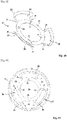
- figure 5 shows more particularly the bottom 2a of the combustible casing 2.
- the casing 2 comprises three peripheral vents 21, regularly distributed angularly around the axis of the case 2. These openings 21 are intended to allow the case 2 to be loaded with a propellant charge. At least one vent would be sufficient for loading, but three vents make it even easier to evenly distribute the propellant charge in the case. It is of course possible to provide a different number of openings: for example two openings or more than three openings.
- the bottom of the case carries three combustible tongues 22 which are regularly distributed angularly and which are secured to the bottom 2a of the case 2 in the vicinity of the axial opening 20.
- the tabs 22 have an S-shaped profile as seen in figure 1 , profile whose free end extends above the axial opening 20. They are glued to the case 2, for example by a combustible glue. Such glues are well known to those skilled in the art.
- the tabs 22 are intended to constitute a stop surface for the retaining ring 19 of the ignition means 8.
- the ignition means 8 When the ignition means 8 is positioned in the case 2, it caps the opening 20 of the case and is placed in abutment on the tabs 22. It is noted in fact that the notches 15 of the abutment ring 12 comprise a profile 23 ( figures 1 and 2 ) which bears against the upper end of the tabs 22.
- the elastic washer 17 comprises a crown 24 bearing at its periphery three wings elastic 25.
- the wings 25 are curved with respect to the crown 24 and are intended to come into contact with the case 2 along the curved part 2b of the latter which connects the bottom 2a to the cylindrical part 2c of the case.
- the wings 25 are perforated and have openings 26 which facilitate the combustion of the case 2 during firing while allowing the elasticity of the wings to be controlled.
- the three wings 25 are positioned alternately with the three loading openings 21.
- notches 27 ( figure 6 ) which are arranged on the internal circular profile of the washer 17. These notches are intended to cooperate with the tongues 22 of the fuel casing 2. They thus ensure a locking in rotation of the washer 17 with respect to the casing 2.
- the notches 15 of the stop ring 12 also cover the tongues 22. These notches have the same width as the tongues 22 and they therefore constitute a means preventing the rotation of the stop ring 12 (therefore of the ignition means 8) with respect to the case 2.
- the holding means which comprise, on the one hand the stop ring 12 fixed to the ignition means 8 and on the other hand the holding ring 19 fixed to the ignition means 8 and which cooperates with the stop surface formed by the tabs 22, ensure a positioning of the ignition means 8 relative to the case 2 which allows the case 2 to be loaded with the propellant powder, while preventing any rotation and translation of the ignition means 8 with respect to the case 2.
- the base 4 is positioned on the rear extension 8c of the metal body 8a of the means ignition 8 and the base 4 is fixed to the ignition means and to the case 2 by fitting the nut 7.
- the figures 7 to 11 show another embodiment of a connecting device according to the invention.
- This mode differs from the previous one essentially by the nature of the stop surface against which the retaining ring 19 is applied.
- This second embodiment proposes making the stop surface in the form of a ring 28 which is intended to be positioned in the axial opening 20 of the case.
- the ring 28 is more particularly visible at the figure 9 . It has an S-shaped section and comprises an external flange 29 which is intended to be applied to an external surface 2d of the bottom of the case 2.
- the ring 28 also comprises an internal flange 30 which extends to the inside the opening 20 and on which the retaining ring 19 will be applied.
- the opening 20 may be counterbored on its exterior. This countersinking will make it possible to embed the thickness of the outer collar 29 of the ring 28 in the thickness of the fuel casing.
- this embodiment includes other modifications with respect to the previous mode.
- the elastic washer 17 comprises a ring 24 bearing at its periphery three elastic wings 25.
- the wings 25 are curved with respect to the ring 24 and are intended to come into contact with the case 2 along the curved part 2b of that -ci which connects the bottom 2a to the cylindrical part 2c of the case.
- the wings 25 are perforated and have openings 26 which facilitate the combustion of the case 2 during firing while allowing the elasticity of the wings to be controlled.
- the three wings 25 are positioned alternately with the three loading openings 21 made on the case 2.
- this washer 17 comprises at least two lower strips 31 which are intended to be positioned against the edges of one or more openings 21 of the case 2.
- the lower slats 31 are positioned on the edges of the elastic flanges 25. Indeed each flange 25 of the washer 17 covers the entire sector separating two openings 21 consecutive. It is therefore easy to engage inside two neighboring vents 21 lower slats 31 which are carried by the side edges of a wing 25.
- the elastic washer 17 comprises at least one upper lamella 32 which is carried by the crown 24 and which is intended to cooperate with a slot 33 of the thrust ring 12.
- upper slats 32 regularly distributed angularly and which engage in four slots 33 of the stop ring (see the figure 8 ).
- the number of upper slats 32 and slots could be different.
- the upper and lower slats will easily be obtained by cutting and bending during the manufacture of the washer 17.
- the holding means according to the invention which comprise, on the one hand the stop ring 12 integral with the ignition means 8 and on the other hand the holding ring 19 integral with the ignition means 8 and which cooperates with the stop surface formed by the ring 28, ensure a positioning of the ignition means 8 relative to the case 2 which allows the case 2 to be loaded with the propellant powder, while preventing any rotation and translation of the ignition means 8 relative to the case 2.
- the base 4 is positioned on the rear extension 8c of the metal body 8a of the ignition means 8 and the base 4 is fixed to the ignition means and to the case 2 by placing the nut 7.
Landscapes
- Engineering & Computer Science (AREA)
- General Engineering & Computer Science (AREA)
- Ignition Installations For Internal Combustion Engines (AREA)
- Connector Housings Or Holding Contact Members (AREA)
- Bolts, Nuts, And Washers (AREA)
- Filling Or Discharging Of Gas Storage Vessels (AREA)
Applications Claiming Priority (1)
| Application Number | Priority Date | Filing Date | Title |
|---|---|---|---|
| FR2100599A FR3119231B1 (fr) | 2021-01-26 | 2021-01-26 | Dispositif de liaison entre un moyen d'allumage d'une charge propulsive et un etui combustible d'une munition, etui combustible et rondelle elastique associes a un tel dispositif de liaison. |
Publications (2)
| Publication Number | Publication Date |
|---|---|
| EP4033198A1 true EP4033198A1 (de) | 2022-07-27 |
| EP4033198B1 EP4033198B1 (de) | 2025-04-16 |
Family
ID=75690390
Family Applications (1)
| Application Number | Title | Priority Date | Filing Date |
|---|---|---|---|
| EP22153374.8A Active EP4033198B1 (de) | 2021-01-26 | 2022-01-26 | Verbindungsvorrichtung zwischen einem zündmittel einer treibladung und einer verbrennbaren hülse einer munition, verbrennbare hülse und elastische unterlegscheibe, die mit einer solchen verbindungsvorrichtung zusammenwirken |
Country Status (3)
| Country | Link |
|---|---|
| EP (1) | EP4033198B1 (de) |
| ES (1) | ES3035772T3 (de) |
| FR (1) | FR3119231B1 (de) |
Citations (6)
| Publication number | Priority date | Publication date | Assignee | Title |
|---|---|---|---|---|
| FR2365096A1 (fr) | 1976-09-16 | 1978-04-14 | Rheinmetall Gmbh | Douille pour charge propulsive |
| EP0463904A1 (de) | 1990-06-25 | 1992-01-02 | Societe Nationale Des Poudres Et Explosifs | Patronenhülsenelement mit verbrennbarer Hülse, mit einem solchen Element versehene halbverbrennbare Munition und Verfahren zum Laden dieser Munition |
| EP1092939A1 (de) | 1999-10-13 | 2001-04-18 | Giat Industries | Vorrichtung zum Befestigen eines Hülsenbodens an einer Treibladungshülse und Hülsenboden für eine solche Befestigungseinrichtung |
| DE60104950T2 (de) * | 2000-03-23 | 2005-01-05 | Giat Industries | Anzündrohr für artilleriemunition |
| DE60011011T2 (de) * | 1999-10-13 | 2005-05-25 | Giat Industries | Anzündvorrichtung für eine Treibladung |
| EP3715776A1 (de) | 2019-03-27 | 2020-09-30 | Nexter Munitions | Patrone mit zündschnüren |
-
2021
- 2021-01-26 FR FR2100599A patent/FR3119231B1/fr active Active
-
2022
- 2022-01-26 ES ES22153374T patent/ES3035772T3/es active Active
- 2022-01-26 EP EP22153374.8A patent/EP4033198B1/de active Active
Patent Citations (6)
| Publication number | Priority date | Publication date | Assignee | Title |
|---|---|---|---|---|
| FR2365096A1 (fr) | 1976-09-16 | 1978-04-14 | Rheinmetall Gmbh | Douille pour charge propulsive |
| EP0463904A1 (de) | 1990-06-25 | 1992-01-02 | Societe Nationale Des Poudres Et Explosifs | Patronenhülsenelement mit verbrennbarer Hülse, mit einem solchen Element versehene halbverbrennbare Munition und Verfahren zum Laden dieser Munition |
| EP1092939A1 (de) | 1999-10-13 | 2001-04-18 | Giat Industries | Vorrichtung zum Befestigen eines Hülsenbodens an einer Treibladungshülse und Hülsenboden für eine solche Befestigungseinrichtung |
| DE60011011T2 (de) * | 1999-10-13 | 2005-05-25 | Giat Industries | Anzündvorrichtung für eine Treibladung |
| DE60104950T2 (de) * | 2000-03-23 | 2005-01-05 | Giat Industries | Anzündrohr für artilleriemunition |
| EP3715776A1 (de) | 2019-03-27 | 2020-09-30 | Nexter Munitions | Patrone mit zündschnüren |
Also Published As
| Publication number | Publication date |
|---|---|
| FR3119231B1 (fr) | 2023-10-20 |
| ES3035772T3 (en) | 2025-09-09 |
| EP4033198B1 (de) | 2025-04-16 |
| FR3119231A1 (fr) | 2022-07-29 |
Similar Documents
| Publication | Publication Date | Title |
|---|---|---|
| EP0640205B1 (de) | Hülse für teleskopische munitionen | |
| EP0781692B1 (de) | Scheibenwischer-Mechanismus mit Führungs-und Dichtungsmittel zur Antriebaxen-Durchquerung eines Bleches | |
| EP3715776B1 (de) | Patrone mit zündschnüren | |
| FR2720495A1 (fr) | Dispositif permettant de solidariser deux conteneurs et conteneur associé à un tel dispositif. | |
| EP4033198B1 (de) | Verbindungsvorrichtung zwischen einem zündmittel einer treibladung und einer verbrennbaren hülse einer munition, verbrennbare hülse und elastische unterlegscheibe, die mit einer solchen verbindungsvorrichtung zusammenwirken | |
| EP0660070A1 (de) | Treibladungsbehälter und Verfahren zu seiner Herstellung | |
| EP0594482B1 (de) | Treibladungsbehälter | |
| EP0691520B1 (de) | Vorrichtung zur Verbindung von zwei Behältern und Behälter dafür | |
| EP3109507B1 (de) | Gedämpftes doppellenkrad, das mit einer vorrichtung zur vorübergehenden immobilisierung ausgestattet ist | |
| EP3489617B1 (de) | Projektil | |
| WO2019002219A1 (fr) | Charge formée | |
| FR2799694A1 (fr) | Dispositif de support superieur pour ressort de suspension, notamment automobile | |
| EP0681679B1 (de) | Treibladungsbehälter der mit einem anderen behälter verbindbar ist | |
| EP2108916A1 (de) | Großkalibrige, von hinten gefüllte Munition | |
| FR2702554A1 (fr) | Munition, en particulier pour arme de gros calibre. | |
| EP0281462B1 (de) | Munition, insbesondere für Artillerie, bestehend aus einem Geschoss und einer Hülse | |
| EP0526316B1 (de) | Munition, insbesondere Teleskopartige Munition | |
| FR2785263A1 (fr) | Dispositif de remplissage d'un reservoir de carburant de vehicule automobile | |
| LU79883A1 (fr) | Emboitement de canalisation | |
| FR2738298A1 (fr) | Demarreur pour un moteur de vehicule automobile comportant des moyens perfectionnes d'etancheite | |
| FR2741144A1 (fr) | Charge formee comportant des moyens de maintien du revetement | |
| FR2715721A1 (fr) | Obus gyrostabilisé de transport de charge utile. | |
| FR2888923A1 (fr) | Munition et procede de montage d'une telle munition | |
| WO2022049465A1 (fr) | Douille combustible pour munition | |
| FR2940381A1 (fr) | Bague de synchronisation pour une boite de vitesses |
Legal Events
| Date | Code | Title | Description |
|---|---|---|---|
| PUAI | Public reference made under article 153(3) epc to a published international application that has entered the european phase |
Free format text: ORIGINAL CODE: 0009012 |
|
| STAA | Information on the status of an ep patent application or granted ep patent |
Free format text: STATUS: THE APPLICATION HAS BEEN PUBLISHED |
|
| AK | Designated contracting states |
Kind code of ref document: A1 Designated state(s): AL AT BE BG CH CY CZ DE DK EE ES FI FR GB GR HR HU IE IS IT LI LT LU LV MC MK MT NL NO PL PT RO RS SE SI SK SM TR |
|
| STAA | Information on the status of an ep patent application or granted ep patent |
Free format text: STATUS: REQUEST FOR EXAMINATION WAS MADE |
|
| 17P | Request for examination filed |
Effective date: 20230124 |
|
| RBV | Designated contracting states (corrected) |
Designated state(s): AL AT BE BG CH CY CZ DE DK EE ES FI FR GB GR HR HU IE IS IT LI LT LU LV MC MK MT NL NO PL PT RO RS SE SI SK SM TR |
|
| P01 | Opt-out of the competence of the unified patent court (upc) registered |
Effective date: 20231212 |
|
| RAP3 | Party data changed (applicant data changed or rights of an application transferred) |
Owner name: KNDS AMMO FRANCE |
|
| GRAP | Despatch of communication of intention to grant a patent |
Free format text: ORIGINAL CODE: EPIDOSNIGR1 |
|
| STAA | Information on the status of an ep patent application or granted ep patent |
Free format text: STATUS: GRANT OF PATENT IS INTENDED |
|
| INTG | Intention to grant announced |
Effective date: 20241112 |
|
| GRAS | Grant fee paid |
Free format text: ORIGINAL CODE: EPIDOSNIGR3 |
|
| GRAA | (expected) grant |
Free format text: ORIGINAL CODE: 0009210 |
|
| STAA | Information on the status of an ep patent application or granted ep patent |
Free format text: STATUS: THE PATENT HAS BEEN GRANTED |
|
| AK | Designated contracting states |
Kind code of ref document: B1 Designated state(s): AL AT BE BG CH CY CZ DE DK EE ES FI FR GB GR HR HU IE IS IT LI LT LU LV MC MK MT NL NO PL PT RO RS SE SI SK SM TR |
|
| REG | Reference to a national code |
Ref country code: GB Ref legal event code: FG4D Free format text: NOT ENGLISH |
|
| REG | Reference to a national code |
Ref country code: CH Ref legal event code: EP Ref country code: DE Ref legal event code: R096 Ref document number: 602022013080 Country of ref document: DE |
|
| REG | Reference to a national code |
Ref country code: IE Ref legal event code: FG4D Free format text: LANGUAGE OF EP DOCUMENT: FRENCH |
|
| REG | Reference to a national code |
Ref country code: NL Ref legal event code: MP Effective date: 20250416 |
|
| REG | Reference to a national code |
Ref country code: ES Ref legal event code: FG2A Ref document number: 3035772 Country of ref document: ES Kind code of ref document: T3 Effective date: 20250909 |
|
| PG25 | Lapsed in a contracting state [announced via postgrant information from national office to epo] |
Ref country code: NL Free format text: LAPSE BECAUSE OF FAILURE TO SUBMIT A TRANSLATION OF THE DESCRIPTION OR TO PAY THE FEE WITHIN THE PRESCRIBED TIME-LIMIT Effective date: 20250416 |
|
| REG | Reference to a national code |
Ref country code: AT Ref legal event code: MK05 Ref document number: 1785944 Country of ref document: AT Kind code of ref document: T Effective date: 20250416 |
|
| PG25 | Lapsed in a contracting state [announced via postgrant information from national office to epo] |
Ref country code: FI Free format text: LAPSE BECAUSE OF FAILURE TO SUBMIT A TRANSLATION OF THE DESCRIPTION OR TO PAY THE FEE WITHIN THE PRESCRIBED TIME-LIMIT Effective date: 20250416 Ref country code: PT Free format text: LAPSE BECAUSE OF FAILURE TO SUBMIT A TRANSLATION OF THE DESCRIPTION OR TO PAY THE FEE WITHIN THE PRESCRIBED TIME-LIMIT Effective date: 20250818 |
|
| REG | Reference to a national code |
Ref country code: LT Ref legal event code: MG9D |
|
| PG25 | Lapsed in a contracting state [announced via postgrant information from national office to epo] |
Ref country code: GR Free format text: LAPSE BECAUSE OF FAILURE TO SUBMIT A TRANSLATION OF THE DESCRIPTION OR TO PAY THE FEE WITHIN THE PRESCRIBED TIME-LIMIT Effective date: 20250717 |
|
| PG25 | Lapsed in a contracting state [announced via postgrant information from national office to epo] |
Ref country code: PL Free format text: LAPSE BECAUSE OF FAILURE TO SUBMIT A TRANSLATION OF THE DESCRIPTION OR TO PAY THE FEE WITHIN THE PRESCRIBED TIME-LIMIT Effective date: 20250416 |
|
| PG25 | Lapsed in a contracting state [announced via postgrant information from national office to epo] |
Ref country code: BG Free format text: LAPSE BECAUSE OF FAILURE TO SUBMIT A TRANSLATION OF THE DESCRIPTION OR TO PAY THE FEE WITHIN THE PRESCRIBED TIME-LIMIT Effective date: 20250416 |
|
| PG25 | Lapsed in a contracting state [announced via postgrant information from national office to epo] |
Ref country code: HR Free format text: LAPSE BECAUSE OF FAILURE TO SUBMIT A TRANSLATION OF THE DESCRIPTION OR TO PAY THE FEE WITHIN THE PRESCRIBED TIME-LIMIT Effective date: 20250416 |
|
| PG25 | Lapsed in a contracting state [announced via postgrant information from national office to epo] |
Ref country code: AT Free format text: LAPSE BECAUSE OF FAILURE TO SUBMIT A TRANSLATION OF THE DESCRIPTION OR TO PAY THE FEE WITHIN THE PRESCRIBED TIME-LIMIT Effective date: 20250416 |
|
| PG25 | Lapsed in a contracting state [announced via postgrant information from national office to epo] |
Ref country code: RS Free format text: LAPSE BECAUSE OF FAILURE TO SUBMIT A TRANSLATION OF THE DESCRIPTION OR TO PAY THE FEE WITHIN THE PRESCRIBED TIME-LIMIT Effective date: 20250716 |
|
| PG25 | Lapsed in a contracting state [announced via postgrant information from national office to epo] |
Ref country code: IS Free format text: LAPSE BECAUSE OF FAILURE TO SUBMIT A TRANSLATION OF THE DESCRIPTION OR TO PAY THE FEE WITHIN THE PRESCRIBED TIME-LIMIT Effective date: 20250816 |
|
| PG25 | Lapsed in a contracting state [announced via postgrant information from national office to epo] |
Ref country code: LV Free format text: LAPSE BECAUSE OF FAILURE TO SUBMIT A TRANSLATION OF THE DESCRIPTION OR TO PAY THE FEE WITHIN THE PRESCRIBED TIME-LIMIT Effective date: 20250416 |
|
| PGFP | Annual fee paid to national office [announced via postgrant information from national office to epo] |
Ref country code: GB Payment date: 20251220 Year of fee payment: 5 |
|
| PGFP | Annual fee paid to national office [announced via postgrant information from national office to epo] |
Ref country code: NO Payment date: 20251218 Year of fee payment: 5 |
|
| PG25 | Lapsed in a contracting state [announced via postgrant information from national office to epo] |
Ref country code: SM Free format text: LAPSE BECAUSE OF FAILURE TO SUBMIT A TRANSLATION OF THE DESCRIPTION OR TO PAY THE FEE WITHIN THE PRESCRIBED TIME-LIMIT Effective date: 20250416 Ref country code: DK Free format text: LAPSE BECAUSE OF FAILURE TO SUBMIT A TRANSLATION OF THE DESCRIPTION OR TO PAY THE FEE WITHIN THE PRESCRIBED TIME-LIMIT Effective date: 20250416 |
|
| PGFP | Annual fee paid to national office [announced via postgrant information from national office to epo] |
Ref country code: FR Payment date: 20251217 Year of fee payment: 5 |
|
| REG | Reference to a national code |
Ref country code: DE Ref legal event code: R097 Ref document number: 602022013080 Country of ref document: DE |
|
| PG25 | Lapsed in a contracting state [announced via postgrant information from national office to epo] |
Ref country code: CZ Free format text: LAPSE BECAUSE OF FAILURE TO SUBMIT A TRANSLATION OF THE DESCRIPTION OR TO PAY THE FEE WITHIN THE PRESCRIBED TIME-LIMIT Effective date: 20250416 |
|
| PG25 | Lapsed in a contracting state [announced via postgrant information from national office to epo] |
Ref country code: EE Free format text: LAPSE BECAUSE OF FAILURE TO SUBMIT A TRANSLATION OF THE DESCRIPTION OR TO PAY THE FEE WITHIN THE PRESCRIBED TIME-LIMIT Effective date: 20250416 |
|
| PG25 | Lapsed in a contracting state [announced via postgrant information from national office to epo] |
Ref country code: SK Free format text: LAPSE BECAUSE OF FAILURE TO SUBMIT A TRANSLATION OF THE DESCRIPTION OR TO PAY THE FEE WITHIN THE PRESCRIBED TIME-LIMIT Effective date: 20250416 |
|
| PLBE | No opposition filed within time limit |
Free format text: ORIGINAL CODE: 0009261 |
|
| STAA | Information on the status of an ep patent application or granted ep patent |
Free format text: STATUS: NO OPPOSITION FILED WITHIN TIME LIMIT |
|
| REG | Reference to a national code |
Ref country code: CH Ref legal event code: L10 Free format text: ST27 STATUS EVENT CODE: U-0-0-L10-L00 (AS PROVIDED BY THE NATIONAL OFFICE) Effective date: 20260225 |
|
| 26N | No opposition filed |
Effective date: 20260119 |
|
| PGFP | Annual fee paid to national office [announced via postgrant information from national office to epo] |
Ref country code: ES Payment date: 20260202 Year of fee payment: 5 |
|
| PGFP | Annual fee paid to national office [announced via postgrant information from national office to epo] |
Ref country code: IT Payment date: 20260107 Year of fee payment: 5 |