EP4033584A1 - Speicherbatterievorrichtung - Google Patents
Speicherbatterievorrichtung Download PDFInfo
- Publication number
- EP4033584A1 EP4033584A1 EP19945830.8A EP19945830A EP4033584A1 EP 4033584 A1 EP4033584 A1 EP 4033584A1 EP 19945830 A EP19945830 A EP 19945830A EP 4033584 A1 EP4033584 A1 EP 4033584A1
- Authority
- EP
- European Patent Office
- Prior art keywords
- battery
- management unit
- battery module
- current
- communication
- Prior art date
- Legal status (The legal status is an assumption and is not a legal conclusion. Google has not performed a legal analysis and makes no representation as to the accuracy of the status listed.)
- Pending
Links
Images




Classifications
-
- H—ELECTRICITY
- H02—GENERATION; CONVERSION OR DISTRIBUTION OF ELECTRIC POWER
- H02J—ELECTRIC POWER NETWORKS; CIRCUIT ARRANGEMENTS OR SYSTEMS FOR SUPPLYING OR DISTRIBUTING ELECTRIC POWER; SYSTEMS FOR STORING ELECTRIC ENERGY
- H02J7/00—Circuit arrangements for charging or discharging batteries or for supplying loads from batteries
- H02J7/80—Circuit arrangements for charging or discharging batteries or for supplying loads from batteries including monitoring or indicating arrangements
-
- H—ELECTRICITY
- H02—GENERATION; CONVERSION OR DISTRIBUTION OF ELECTRIC POWER
- H02J—ELECTRIC POWER NETWORKS; CIRCUIT ARRANGEMENTS OR SYSTEMS FOR SUPPLYING OR DISTRIBUTING ELECTRIC POWER; SYSTEMS FOR STORING ELECTRIC ENERGY
- H02J7/00—Circuit arrangements for charging or discharging batteries or for supplying loads from batteries
- H02J7/90—Regulation of charging or discharging current or voltage
- H02J7/94—Regulation of charging or discharging current or voltage in response to battery current
-
- H—ELECTRICITY
- H01—ELECTRIC ELEMENTS
- H01M—PROCESSES OR MEANS, e.g. BATTERIES, FOR THE DIRECT CONVERSION OF CHEMICAL ENERGY INTO ELECTRICAL ENERGY
- H01M10/00—Secondary cells; Manufacture thereof
- H01M10/42—Methods or arrangements for servicing or maintenance of secondary cells or secondary half-cells
- H01M10/425—Structural combination with electronic components, e.g. electronic circuits integrated to the outside of the casing
-
- H—ELECTRICITY
- H01—ELECTRIC ELEMENTS
- H01M—PROCESSES OR MEANS, e.g. BATTERIES, FOR THE DIRECT CONVERSION OF CHEMICAL ENERGY INTO ELECTRICAL ENERGY
- H01M10/00—Secondary cells; Manufacture thereof
- H01M10/42—Methods or arrangements for servicing or maintenance of secondary cells or secondary half-cells
- H01M10/44—Methods for charging or discharging
-
- H—ELECTRICITY
- H01—ELECTRIC ELEMENTS
- H01M—PROCESSES OR MEANS, e.g. BATTERIES, FOR THE DIRECT CONVERSION OF CHEMICAL ENERGY INTO ELECTRICAL ENERGY
- H01M10/00—Secondary cells; Manufacture thereof
- H01M10/42—Methods or arrangements for servicing or maintenance of secondary cells or secondary half-cells
- H01M10/48—Accumulators combined with arrangements for measuring, testing or indicating the condition of cells, e.g. the level or density of the electrolyte
-
- H—ELECTRICITY
- H01—ELECTRIC ELEMENTS
- H01M—PROCESSES OR MEANS, e.g. BATTERIES, FOR THE DIRECT CONVERSION OF CHEMICAL ENERGY INTO ELECTRICAL ENERGY
- H01M10/00—Secondary cells; Manufacture thereof
- H01M10/42—Methods or arrangements for servicing or maintenance of secondary cells or secondary half-cells
- H01M10/48—Accumulators combined with arrangements for measuring, testing or indicating the condition of cells, e.g. the level or density of the electrolyte
- H01M10/482—Accumulators combined with arrangements for measuring, testing or indicating the condition of cells, e.g. the level or density of the electrolyte for several batteries or cells simultaneously or sequentially
-
- H—ELECTRICITY
- H01—ELECTRIC ELEMENTS
- H01M—PROCESSES OR MEANS, e.g. BATTERIES, FOR THE DIRECT CONVERSION OF CHEMICAL ENERGY INTO ELECTRICAL ENERGY
- H01M10/00—Secondary cells; Manufacture thereof
- H01M10/42—Methods or arrangements for servicing or maintenance of secondary cells or secondary half-cells
- H01M10/48—Accumulators combined with arrangements for measuring, testing or indicating the condition of cells, e.g. the level or density of the electrolyte
- H01M10/486—Accumulators combined with arrangements for measuring, testing or indicating the condition of cells, e.g. the level or density of the electrolyte for measuring temperature
-
- H—ELECTRICITY
- H02—GENERATION; CONVERSION OR DISTRIBUTION OF ELECTRIC POWER
- H02J—ELECTRIC POWER NETWORKS; CIRCUIT ARRANGEMENTS OR SYSTEMS FOR SUPPLYING OR DISTRIBUTING ELECTRIC POWER; SYSTEMS FOR STORING ELECTRIC ENERGY
- H02J7/00—Circuit arrangements for charging or discharging batteries or for supplying loads from batteries
- H02J7/40—Circuit arrangements for charging or discharging batteries or for supplying loads from batteries characterised by the exchange of charge or discharge related data
-
- H—ELECTRICITY
- H02—GENERATION; CONVERSION OR DISTRIBUTION OF ELECTRIC POWER
- H02J—ELECTRIC POWER NETWORKS; CIRCUIT ARRANGEMENTS OR SYSTEMS FOR SUPPLYING OR DISTRIBUTING ELECTRIC POWER; SYSTEMS FOR STORING ELECTRIC ENERGY
- H02J7/00—Circuit arrangements for charging or discharging batteries or for supplying loads from batteries
- H02J7/50—Circuit arrangements for charging or discharging batteries or for supplying loads from batteries acting upon multiple batteries simultaneously or sequentially
-
- H—ELECTRICITY
- H02—GENERATION; CONVERSION OR DISTRIBUTION OF ELECTRIC POWER
- H02J—ELECTRIC POWER NETWORKS; CIRCUIT ARRANGEMENTS OR SYSTEMS FOR SUPPLYING OR DISTRIBUTING ELECTRIC POWER; SYSTEMS FOR STORING ELECTRIC ENERGY
- H02J7/00—Circuit arrangements for charging or discharging batteries or for supplying loads from batteries
- H02J7/80—Circuit arrangements for charging or discharging batteries or for supplying loads from batteries including monitoring or indicating arrangements
- H02J7/82—Control of state of charge [SOC]
-
- H—ELECTRICITY
- H02—GENERATION; CONVERSION OR DISTRIBUTION OF ELECTRIC POWER
- H02J—ELECTRIC POWER NETWORKS; CIRCUIT ARRANGEMENTS OR SYSTEMS FOR SUPPLYING OR DISTRIBUTING ELECTRIC POWER; SYSTEMS FOR STORING ELECTRIC ENERGY
- H02J7/00—Circuit arrangements for charging or discharging batteries or for supplying loads from batteries
- H02J7/80—Circuit arrangements for charging or discharging batteries or for supplying loads from batteries including monitoring or indicating arrangements
- H02J7/84—Control of state of health [SOH]
-
- H—ELECTRICITY
- H01—ELECTRIC ELEMENTS
- H01M—PROCESSES OR MEANS, e.g. BATTERIES, FOR THE DIRECT CONVERSION OF CHEMICAL ENERGY INTO ELECTRICAL ENERGY
- H01M10/00—Secondary cells; Manufacture thereof
- H01M10/42—Methods or arrangements for servicing or maintenance of secondary cells or secondary half-cells
- H01M10/425—Structural combination with electronic components, e.g. electronic circuits integrated to the outside of the casing
- H01M2010/4271—Battery management systems including electronic circuits, e.g. control of current or voltage to keep battery in healthy state, cell balancing
-
- H—ELECTRICITY
- H01—ELECTRIC ELEMENTS
- H01M—PROCESSES OR MEANS, e.g. BATTERIES, FOR THE DIRECT CONVERSION OF CHEMICAL ENERGY INTO ELECTRICAL ENERGY
- H01M10/00—Secondary cells; Manufacture thereof
- H01M10/42—Methods or arrangements for servicing or maintenance of secondary cells or secondary half-cells
- H01M10/425—Structural combination with electronic components, e.g. electronic circuits integrated to the outside of the casing
- H01M2010/4278—Systems for data transfer from batteries, e.g. transfer of battery parameters to a controller, data transferred between battery controller and main controller
-
- Y—GENERAL TAGGING OF NEW TECHNOLOGICAL DEVELOPMENTS; GENERAL TAGGING OF CROSS-SECTIONAL TECHNOLOGIES SPANNING OVER SEVERAL SECTIONS OF THE IPC; TECHNICAL SUBJECTS COVERED BY FORMER USPC CROSS-REFERENCE ART COLLECTIONS [XRACs] AND DIGESTS
- Y02—TECHNOLOGIES OR APPLICATIONS FOR MITIGATION OR ADAPTATION AGAINST CLIMATE CHANGE
- Y02E—REDUCTION OF GREENHOUSE GAS [GHG] EMISSIONS, RELATED TO ENERGY GENERATION, TRANSMISSION OR DISTRIBUTION
- Y02E60/00—Enabling technologies; Technologies with a potential or indirect contribution to GHG emissions mitigation
- Y02E60/10—Energy storage using batteries
Definitions
- the present invention relates to a storage battery apparatus.
- a storage battery apparatus obtained by combining a plurality of storage battery modules is used for various purposes.
- it has been studied to achieve wireless communication between a storage battery module and a management apparatus using radio waves.
- Embodiments of the present invention have been made in view of the above circumstances, and an object thereof is to provide a storage battery apparatus with high reliability which performs communication using radio waves.
- a storage battery apparatus includes: a plurality of storage battery modules, each of the storage battery modules including a battery module including a plurality of battery cells, and a cell monitoring unit configured to measure voltages of the battery cells and a temperature of at least one portion of the battery module; and a battery management unit configured to perform communication with the plurality of cell monitoring units using a radio wave and periodically receive measurement values of the voltages of the battery cells and a measurement value of the temperature of the battery module.
- the battery management unit extends a communication cycle with the cell monitoring units, sets a value of a chargeable current and a value of a dischargeable current of the battery module, which correspond to at least the communication cycle, and notifies a host apparatus of the set values.
- FIG. 1 is a diagram schematically illustrating a configuration example of a storage battery apparatus according to an embodiment.
- the storage battery apparatus of the present embodiment includes a plurality of storage battery modules MDL, a battery management unit (BMU) 20, a current sensor SS, and electromagnetic contactors CP and CM.
- BMU battery management unit
- CP and CM electromagnetic contactors
- the storage battery module MDL includes a battery module BT including a plurality of battery cells (not illustrated), and a cell monitoring unit (CMU) 10.
- a battery module BT including a plurality of battery cells (not illustrated), and a cell monitoring unit (CMU) 10.
- CMU cell monitoring unit
- the battery module BT includes, for example, a plurality of battery cells of lithium ion batteries connected in series or in parallel.
- the cell monitoring unit 10 includes a measurement circuit which detects a voltage of each of the plurality of battery cells and a temperature of at least one portion of the battery module BT, and a wireless transmission/reception circuit (not illustrated) capable of performing wireless communication with the battery management unit 20 using radio waves, and can periodically transmit a measurement value to the battery management unit 20.
- the cell monitoring unit 10 equalizes the voltages (cell balance) of the plurality of battery cells based on a control signal received from the battery management unit 20.
- the cell monitoring unit 10 may be configured with, for example, hardware, software, or a combination of hardware and software.
- the cell monitoring unit 10 is a circuit which includes, for example, at least one processor such as a CPU and an MPU, and a memory in which a program to be executed by the processor is recorded, and which realizes the above operation by software.
- a total of 300 battery cells are connected in series by connecting the plurality of storage battery modules MDL in series, and a voltage between a main circuit on a high electric potential side and a main circuit on a low electric potential side at the time of full charge is set at 10 kV.
- the current sensor SS detects a value of a current flowing through the main circuit on the high electric potential side, and supplies a detection value to the battery management unit 20.
- the electromagnetic contactor CN is interposed in a main circuit which connects a terminal on the lowest electric potential side of the plurality of storage battery modules MDL and a negative electrode terminal, and can switch an electrical connection between the plurality of storage battery modules MDL and the negative electrode terminal.
- the electromagnetic contactor CN is controlled to open and close the contact by a control signal from the battery management unit 20.
- the electromagnetic contactor CP is interposed in a main circuit which connects a terminal on the highest electric potential side of the plurality of storage battery modules MDL and a positive electrode terminal, and can switch an electrical connection between the plurality of storage battery modules MDL and the positive electrode terminal.
- the electromagnetic contactor CP is controlled to open and close the contact by a control signal from the battery management unit 20.
- the battery management unit 20 can communicate with each of the plurality of cell monitoring units 10 and a host control circuit (not illustrated).
- the battery management unit 20 includes a communication circuit which is capable of performing wireless communication using radio waves with the plurality of cell monitoring units 10 and performing wired communication with the host control circuit.
- the battery management unit 20 can receive various kinds of control signals from the host control circuit and can control operation of the plurality of cell monitoring units 10 and the electromagnetic contactors CN and CP based on the received information.
- the battery management unit 20 periodically receives detection values of the voltages of the plurality of battery cells (or the battery modules BT) and a detection value of the temperature of the battery module BT from each of the plurality of cell monitoring units 10, and periodically receives a detection value of current flowing through the plurality of battery modules BT from the current sensor SS.
- the battery management unit 20 can calculate a state of charge (SOC) and a state of health (SOH) of the battery module BT (or the battery cell) based on the received values.
- the battery management unit 20 monitors voltages of the plurality of battery cells and a current flowing through the plurality of battery modules BT, and controls the cell monitoring units 10 so as to equalize the voltages of the plurality of battery cells. For example, the battery management unit 20 controls operation of a battery system so that the battery cell is not in an abnormal state such as over-charge and over-discharge.
- the battery management unit 20 may be configured with hardware, software, or a combination of hardware and software.
- the battery management unit 20 may include, for example, at least one processor, and a memory in which a program to be executed by the processor is recorded.
- FIG. 2 is a diagram for explaining an example of operation of the storage battery apparatus according to the embodiment.
- the battery management unit 20 receives an operation permission notification or a stop notification from a host apparatus (step SA1), the battery management unit 20 transmits a data output command of the measurement value and a cell balance command to the plurality of cell monitoring units 10 (step SA2).
- the battery management unit 20 may transmit the data output command and the cell balance command to the plurality of cell monitoring units 10, or may sequentially transmit the commands to the plurality of cell monitoring units 10 at different timings.
- the cell monitoring unit 10 In a case where the cell monitoring unit 10 receives the data output command and the cell balance command from the battery management unit 20, the cell monitoring unit 10 measures voltages of the plurality of battery cells and a temperature of at least one portion of the battery module BT (step SA3), and transmits the measurement values to the battery management unit 20 (step SA4).
- the battery management unit 20 and the cell monitoring unit10 repeat processing from step SA2 to step SA4 described above.
- the battery management unit 20 receives the measurement values of the voltages and the measurement value of the temperature from the cell monitoring unit 10
- the battery management unit 20 updates the cell balance command based on the received voltage value, and transmits the data output command and the cell balance command to the plurality of cell monitoring units 10 (step SA2).
- a period from when the battery management unit 20 performs processing in step SA2 until when the battery management unit 20 performs processing in the next step SA2 is defined as a communication cycle between the battery management unit 20 and the cell monitoring unit 10.
- the cell monitoring unit 10 updates a state of a cell balance circuit (not illustrated) so as to equalize voltages of the plurality of battery cells in accordance with the cell balance command received from the battery management unit 20 (step SA5).
- the cell monitoring unit 10 switches a switching element of the cell balance circuit (not illustrated) in accordance with the cell balance command received from the battery management unit 20 so as to discharge the battery cell whose voltage is largely different from voltages of other battery cells.
- the battery management unit 20 After the battery management unit 20 receives the measurement values of the voltages and the measurement values of the temperatures from the plurality of cell monitoring units 10, the battery management unit 20 receives a detection value of the current flowing through the main circuit on the high electric potential side from the current sensor SS (step SA6).
- the battery management unit 20 receives the measurement values of the voltages and the temperatures from the cell monitoring units 10 and then receives the measurement value of the current from the current sensor SS.
- the order of the above operation may be reversed, and the operation of receiving the measurement values of the voltages and the temperatures from the cell monitoring units 10 may be performed in parallel to the operation of receiving the measurement value of the current from the current sensor SS.
- the battery management unit 20 performs calculation for setting the communication cycle with the cell monitoring unit 10 and allowable currents (a chargeable current and a dischargeable current) of the battery module BT based on the values of the voltages and the temperature received from the cell monitoring unit 10 and the value received from the current sensor SS (step SA7) .
- the battery management unit 20 determines whether or not a failure due to interference occurs during communication with the plurality of cell monitoring units 10, and extends a communication cycle with the cell monitoring unit 10 in a case where the interference occurs.
- the battery management unit 20 extends the communication cycle with the cell monitoring unit 10, for example, in a case where the number of times of retransmission due to a communication failure reaches equal to or larger than a predetermined number of times in a predetermined period.
- the battery management unit 20 sets values of the chargeable current and the dischargeable current in accordance with the communication cycle, the SOC and the SOH of the battery module BT, and the temperature of the battery module BT, and notifies an apparatus (for example, a host apparatus) which charges and discharges the battery module BT of the set values.
- the battery management unit 20 also determines whether or not to permit charging and discharging to the battery module BT, and makes a notification as to whether or not to permit charging and discharging along with the values of the chargeable current and the dischargeable current (step SA8).
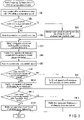
- FIG. 3 is a flowchart for explaining an example of operation of a battery management unit in the storage battery apparatus according to the embodiment. Here, an example of the operation in step 8A of the battery management unit 20 will be described.
- the battery management unit 20 counts the number of times of retransmission as a result of attempting communication with the plurality of cell monitoring units 10 within a predetermined period (step SB1), and determines whether or not the count number exceeds a predetermined threshold (step SB2).
- the battery management unit 20 shortens the communication cycle with the cell monitoring unit 10 in a case where the count number is equal to or less than the predetermined threshold. In other words, the battery management unit 20 shortens the communication cycle by one step in a range between a standard value and a lower limit so as to increase the number of times of communication in the predetermined period.
- the battery management unit 20 can change the communication cycle stepwise within a range from the lower limit value to an upper limit value.
- a time width of one step when the battery management unit 20 extends or shortens the communication cycle stepwise may be adjusted in accordance with the SOC, the temperature, and the like, of the battery module BT. In this event, in a case where the communication cycle with the cell monitoring unit 10 is set at a predetermined standard value, the battery management unit 20 does not change the communication cycle (step SB4).
- the battery management unit 20 extends the communication cycle with the cell monitoring unit 10. In other words, the battery management unit 20 extends the communication cycle by one step in a range between the standard value and the upper limit value so as to reduce the number of times of communication in the predetermined period (step SB3).
- the battery management unit 20 sets the value of the chargeable current and the value of the dischargeable current of the battery module BT using the communication cycle with the cell monitoring unit 10 (step SB5).
- the communication cycle (standard value) in a normal state (in a case where no communication failure occurs) is set at, for example, 0.1 seconds, and the upper limit value of the communication cycle is set at, for example, 1 second.
- the communication cycle is extended from 0.1 seconds to, for example, 0.5 seconds.
- the battery management unit 20 may notify the host apparatus to prohibit charging and discharging without extending the communication cycle.
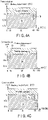
- FIGS. 4A to 4D are diagrams illustrating an example of values of a chargeable current and a dischargeable current corresponding to a communication cycle between a cell monitoring unit and the battery management unit, an SOC and an SOH of a battery module, and a temperature of the battery module.
- an example of the values of the chargeable current and the dischargeable current of the battery module BT in a case where the SOH of the battery module BT is equal to or greater than the predetermined threshold value (a degradation degree is small) is illustrated.
- FIG. 4A illustrates a value of the chargeable current corresponding to the communication cycle and the SOC of the battery module BT in a case where the SOH of the battery module BT is equal to or greater than the predetermined threshold and the temperature of the battery module BT is 25°C.
- FIG. 4B illustrates a value of the dischargeable current corresponding to the communication cycle and the SOC of the battery module BT in a case where the SOH of the battery module BT is equal to or greater than the predetermined threshold and the temperature of the battery module BT is 25°C.
- FIG. 4C illustrates a value of the chargeable current corresponding to the communication cycle and the SOC of the battery module BT in a case where the SOH of the battery module BT is equal to or greater than the predetermined threshold and the temperature of the battery module BT is - 30°C.
- FIG. 4D illustrates a value of the dischargeable current corresponding to the communication cycle and the SOC of the battery module BT in a case where the SOH of the battery module BT is equal to or greater than the predetermined threshold and the temperature of the battery module BT is -30°C.
- the battery management unit 20 may include a plurality of tables in which values of the chargeable currents and the dischargeable currents corresponding to the SOCs and the SOHs of the battery modules BT, the temperatures of the battery modules BT, and the communication cycles illustrated in FIGS. 4A to 4D are stored.
- the battery management unit 20 can select a corresponding table from the SOH and the temperature of the battery module BT and obtain the value of the chargeable current and the value of the dischargeable current corresponding to the communication cycle and the SOC of the battery module BT.
- the battery management unit 20 does not need to include a table for consecutive values for the temperature of the battery module BT, and may correct an error of the obtained value using the table for the value closest to the temperature of the battery module BT to obtain the value of the chargeable current and the value of the dischargeable current.
- the battery management unit 20 can calculate the SOHs of the plurality of battery modules BT based on the measurement values of the voltages and the temperatures received from the plurality of cell monitoring units 10 and the value of the current received from the current sensor SS. In a case where there is a variation in the SOHs of the plurality of battery modules BT, the battery management unit 20 can set the value of the chargeable current and the value of the dischargeable current corresponding to the SOH, the temperature, the SOC, and the communication cycle of the battery module BT having the largest degradation degree as the values of the plurality of battery modules BT.
- the battery management unit 20 can calculate the value of the chargeable current and the value of the dischargeable current from relationship between the SOC of the battery module BT and the communication cycle illustrated in FIGS. 4A and 4B in a case where the SOHs of the plurality of battery modules BT are equal to or greater than the predetermined threshold, and the temperature of the battery module BT is 25°C, by reducing the number of times of communication per unit time by setting the communication cycle at from 0.1 seconds to 0.5 seconds.
- the chargeable current is 3 It [A] and the dischargeable current is 3 It [A] over the entire SOC region of the battery module BT.
- It [A] is a rated current [Ah/h] per unit time.
- the battery management unit 20 can calculate the value of the chargeable current and the value of the dischargeable current from relationship between the SOC of the battery module BT and the communication cycle illustrated in FIGS. 4C and 4D in a case where the SOHs of the plurality of battery modules BT are equal to or greater than the predetermined threshold, and the temperature of the battery module BT is -30°C, by reducing the number of times of communication per unit time by setting the communication cycle at from 0.1 seconds to 1 seconds.
- the chargeable current in a case where the communication cycle is 1 second, the chargeable current is 1 It [A] in a case where the SOC of the battery module BT is equal to or higher than 50%, and the chargeable current is 3 It [A] in a case where the SOC of the battery module BT is less than 50%.
- the dischargeable current in a case where the communication cycle is 1 second, the dischargeable current is 3 It [A] in a case where the SOC of the battery module BT is equal to or higher than 10%, and the dischargeable current is 1 It [A] in a case where the SOC of the battery module BT is less than 10%.
- the battery management unit 20 can calculate the value of the chargeable current and the value of the dischargeable current of the battery module BT based on the temperature and the SOC of the battery module BT and the communication cycle.
- FIGS. 5A and 5B are diagrams illustrating an example of values of a chargeable current and a dischargeable current corresponding to a communication cycle between a cell monitoring unit and the battery management unit, an SOC and an SOH of a battery module, and a temperature of the battery module.
- FIG. 5A illustrates a value of the chargeable current corresponding to the communication cycle and the SOC of the battery module BT in a case where the SOH of the battery module BT is less than the predetermined threshold and the temperature of the battery module BT is 25°C.
- FIG. 5B illustrates a value of the dischargeable current corresponding to the communication cycle and the SOC of the battery module BT in a case where the SOH of the battery module BT is less than the predetermined threshold and the temperature of the battery module BT is 25°C.
- the battery management unit 20 may include a plurality of tables in which values of the chargeable currents and the dischargeable currents corresponding to the SOCs and the SOHs of the battery modules BT, the temperatures of the battery modules BT, and the communication cycles illustrated in FIGS. 5A and 5B are stored. In this event, the battery management unit 20 can select a corresponding table from the SOH and the temperature of the battery module BT and obtain the value of the chargeable current and the value of the dischargeable current corresponding to the communication cycle and the SOC of the battery module BT.
- the battery management unit 20 can calculate the value of the chargeable current and the value of the dischargeable current from relationship between the SOC of the battery module BT and the communication cycle illustrated in FIGS. 5A and 5B in a case where the SOHs of the plurality of battery modules BT are less than the predetermined threshold, and the temperature of the battery module BT is 25°C, by reducing the number of times of communication per unit time by setting the communication cycle at from 0.1 seconds to 0.5 seconds. According to FIG.
- the chargeable current in a case where the communication cycle is 0.5 second, the chargeable current is 1 It [A] in a case where the SOC of the battery module BT is equal to or higher than 80%, and the chargeable current is 3 It [A] in a case where the SOC of the battery module BT is less than 80%.
- the dischargeable current in a case where the communication cycle is 0.5 second, the dischargeable current is 3 It [A] in a case where the SOC of the battery module BT is equal to or higher than 15%, and the dischargeable current is 1 It [A] in a case where the SOC of the battery module BT is less than 15%.
- the battery management unit 20 notifies the host apparatus of the value of the chargeable current and the value of the dischargeable current obtained as described above (step SB6).
- the battery management unit 20 acquires a current value from the current sensor SS (step SB7).
- the battery management unit 20 acquires the current value from the current sensor SS at a predetermined sampling rate over a predetermined period.
- the battery management unit 20 determines whether or not the discharge current of the battery module BT continuously exceeds a limit value (discharge current limit value) in the predetermined period, from the current value in the predetermined period acquired from the current sensor SS (step SB8).
- the limit value of the discharge current is an upper limit value of the current which can be safely discharged continuously, and may be the same as the value of the dischargeable current.
- the battery management unit 20 notifies the host apparatus of permission of discharging (step SB9).
- the battery management unit 20 In a case where the value of the discharge current exceeds the limit value continuously in the predetermined period, the battery management unit 20 notifies the host apparatus of a request for stopping discharging (step SB 10) .
- the battery management unit 20 determines whether or not the charge current of the battery module BT continuously exceeds a limit value (charge current limit value) in the predetermined period, from the current value in the predetermined period acquired from the current sensor SS (step SB11).
- the limit value of the charge current is an upper limit value of the current which can be safely charged continuously, and may be the same as the value of the chargeable current.
- the battery management unit 20 In a case where the value of the charge current does not continuously exceed the limit value in the predetermined period, the battery management unit 20 notifies the host apparatus of permission of charging (step SB12) .
- the battery management unit 20 In a case where the value of the charge current exceeds the limit value continuously in the predetermined period, the battery management unit 20 notifies the host apparatus of a request for stopping charging (step SB 13).
- the battery management unit 20 requests the host apparatus to stop charging or discharging (or both charging and discharging) the battery module BT. This makes it possible to ensure safety of the storage battery apparatus.
- the battery management unit 20 does not need to request to stop discharging of the battery module BT.
- the battery management unit 20 does not need to request to stop charging of the battery module BT.
- the battery management unit 20 determines regarding to the charge and the discharge of the battery module BT in accordance with the value of the SOC of the battery module BT, thereby enhancing the availability of the storage battery apparatus.
- the storage battery apparatus may stop even if the battery module BT is normal. In a case where the storage battery apparatus stops, there is no power supply to a load apparatus, which causes decrease in reliability of the storage battery apparatus.
- the storage battery apparatus of the present embodiment in a case where the battery module BT is normal, in a case where it is temporarily difficult to perform communication between the battery management unit 20 and the cell monitoring unit 10 due to a communication failure, the storage battery apparatus is prevented from stopping, so as to secure the reliability of the storage battery apparatus.
- the storage battery apparatus of the present embodiment it is possible to provide a storage battery apparatus with high reliability which performs communication using radio waves.
- the storage battery apparatus of the present embodiment is similar to the storage battery apparatus in the first embodiment in that wireless communication using radio waves is performed between a battery management unit 20 and cell monitoring units 10, but is different from the battery storage apparatus in the first embodiment in that a communication system for switching a plurality of channels is adopted.
- FIG. 6 is a diagram for explaining an example of a scheme of wireless communication to be performed between the cell monitoring unit and the battery management unit.
- wireless communication is performed between the battery management unit 20 and the cell monitoring units 10 using a communication scheme (for example, Bluetooth (registered trademark)) for switching a plurality of channels through frequency hopping (FH), or the like.
- a communication scheme for example, Bluetooth (registered trademark)
- FH frequency hopping
- one channel is shared by the plurality of cell monitoring units 10.
- FIG. 6 an example of channels used by a first module group MDL1 including the plurality of cell monitoring units 10 and channels used by a second module group MDL2 including the plurality of other cell monitoring units 10 are illustrated in chronological order.
- shading in a frequency direction indicates intensity of an electromagnetic wave.
- a dark portion indicates a strong electromagnetic wave, and a light portion indicates a weak electromagnetic wave.
- a region CHA illustrated in FIG. 6 is a frequency band of an electromagnetic wave greatly affected by interfering radio waves. In a case where a channel overlapping with the region CHA is used, it is difficult to perform communication due to a communication failure.
- FIG. 7 is a diagram for explaining an example of a scheme of wireless communication to be performed between the cell monitoring unit and the battery management unit in the storage battery apparatus of a second embodiment.
- the battery management unit 20 and the plurality of cell monitoring units 10 perform communication using channels while skipping a channel overlapping with the region CHA.
- the plurality of module groups MDL1 and MDL2 perform communication using limited channels, and there is a possibility that the communication cannot be established due to congestion.
- the battery management unit 20 when the number of channels which cannot be used due to interfering radio waves exceeds a predetermined threshold, the battery management unit 20 extends the communication cycle with the cell monitoring unit 10 (reduces the number of times of communication per unit time), and sets the value of the chargeable current and the value of the dischargeable current corresponding to the communication cycle to limit the charge/discharge current.
- FIG. 8 is a flowchart for explaining another example of the operation of the battery management unit in the storage battery apparatus according to an embodiment.
- an example of the operation in step 8A of the battery management unit 20 in the storage battery apparatus according to the first embodiment will be described.
- the battery management unit 20 acquires information on the number of channels which cannot be used due to interfering radio waves (step SC1), and determines whether or not the number of channels which cannot be used exceeds a predetermined threshold (step SC2).
- the battery management unit 20 sets the chargeable current and the dischargeable current of a battery module BT at maximum values of rating, and transmits the set values to the host apparatus (step SC3).
- the battery management unit 20 sets the communication cycle with the cell monitoring unit 10 at a normal value (predetermined standard value) (step SC4).
- the normal value of the communication cycle with the cell monitoring unit 10 is 0.1 seconds.
- the battery management unit 20 sets the values of the chargeable current and the dischargeable current in accordance with the communication cycle, the SOC and the SOH of the battery module BT, and the temperature of the battery module BT by extending the communication cycle with the cell monitoring unit 10, for example, in a similar manner to step SB5 of the first embodiment described above (step SC5).
- Processing from step SC6 to step SC 13 is similar to the processing from step SB6 to step SB13 of the first embodiment described above.
- the storage battery apparatus of the present embodiment in a case where a communication state is poor, by reducing a frequency of communication between the battery management unit 20 and the cell monitoring units 10, a congestion of communication in available channels is avoided, and a situation where the measurement values of the temperatures of the battery modules BT is not received is avoided.
- the storage battery apparatus of the present embodiment it is possible to provide a storage battery apparatus with high reliability which performs communication using radio waves.
Landscapes
- Engineering & Computer Science (AREA)
- Power Engineering (AREA)
- Manufacturing & Machinery (AREA)
- Chemical & Material Sciences (AREA)
- Chemical Kinetics & Catalysis (AREA)
- Electrochemistry (AREA)
- General Chemical & Material Sciences (AREA)
- Microelectronics & Electronic Packaging (AREA)
- Secondary Cells (AREA)
- Charge And Discharge Circuits For Batteries Or The Like (AREA)
- Health & Medical Sciences (AREA)
- General Health & Medical Sciences (AREA)
- Medical Informatics (AREA)
Applications Claiming Priority (1)
| Application Number | Priority Date | Filing Date | Title |
|---|---|---|---|
| PCT/JP2019/036397 WO2021053721A1 (ja) | 2019-09-17 | 2019-09-17 | 蓄電池装置 |
Publications (2)
| Publication Number | Publication Date |
|---|---|
| EP4033584A1 true EP4033584A1 (de) | 2022-07-27 |
| EP4033584A4 EP4033584A4 (de) | 2022-11-09 |
Family
ID=74884027
Family Applications (1)
| Application Number | Title | Priority Date | Filing Date |
|---|---|---|---|
| EP19945830.8A Pending EP4033584A4 (de) | 2019-09-17 | 2019-09-17 | Speicherbatterievorrichtung |
Country Status (5)
| Country | Link |
|---|---|
| US (1) | US12573869B2 (de) |
| EP (1) | EP4033584A4 (de) |
| JP (1) | JP7146106B2 (de) |
| CN (1) | CN113785429B (de) |
| WO (1) | WO2021053721A1 (de) |
Families Citing this family (4)
| Publication number | Priority date | Publication date | Assignee | Title |
|---|---|---|---|---|
| KR20220100332A (ko) * | 2021-01-08 | 2022-07-15 | 주식회사 엘지에너지솔루션 | 배터리 장치 및 전압 공급 방법 |
| WO2023009611A2 (en) | 2021-07-28 | 2023-02-02 | Cps Technology Holdings Llc | Battery data collection for health of battery analysis |
| CN116600371A (zh) * | 2022-02-07 | 2023-08-15 | 华为技术有限公司 | 一种通信方法、装置及系统 |
| KR20230141160A (ko) * | 2022-03-31 | 2023-10-10 | 주식회사 엘지에너지솔루션 | 배터리 셀들간 불균형 방지를 위한 배터리 제어 시스템 및 이의 제어 방법 |
Family Cites Families (22)
| Publication number | Priority date | Publication date | Assignee | Title |
|---|---|---|---|---|
| JPH06343202A (ja) | 1993-06-01 | 1994-12-13 | Nissan Motor Co Ltd | 電気自動車の充電装置 |
| JP4682916B2 (ja) * | 2005-10-11 | 2011-05-11 | 株式会社デンソー | 通信システム及び通信装置 |
| US8761227B2 (en) * | 2008-10-27 | 2014-06-24 | Snu R & Db Foundation | Apparatus and method for avoiding interference noise in FHSS system |
| US8798832B2 (en) * | 2009-03-27 | 2014-08-05 | Hitachi, Ltd. | Electric storage device |
| JP5755540B2 (ja) * | 2011-09-20 | 2015-07-29 | 株式会社東芝 | 蓄電池装置及び蓄電池装置の運転方法 |
| JP2014054003A (ja) | 2012-09-05 | 2014-03-20 | Sharp Corp | 充放電装置および充放電システム |
| WO2014040760A1 (en) * | 2012-09-14 | 2014-03-20 | Siemens Aktiengesellschaft | Method and apparatus for performing energy management in a power supply grid |
| JP6228552B2 (ja) | 2012-12-28 | 2017-11-08 | マクセルホールディングス株式会社 | 組電池システム及び蓄電池システム |
| DE102014200096A1 (de) * | 2014-01-08 | 2015-07-09 | Robert Bosch Gmbh | Batteriemanagementsystem zum Überwachen und Regeln des Betriebs einer Batterie und Batteriesystem mit einem solchen Batteriemanagementsystem |
| DE102014202626A1 (de) * | 2014-02-13 | 2015-08-13 | Robert Bosch Gmbh | Batteriemanagementsystem für eine Batterie mit mehreren Batteriezellen und Verfahren |
| WO2015189898A1 (ja) * | 2014-06-09 | 2015-12-17 | 日立オートモティブシステムズ株式会社 | 電池システム |
| US10193932B2 (en) * | 2014-11-11 | 2019-01-29 | Solarcity Corporation | Real-time energy data publishing systems and methods |
| US9882401B2 (en) * | 2015-11-04 | 2018-01-30 | Powin Energy Corporation | Battery energy storage system |
| JP6560605B2 (ja) | 2015-12-10 | 2019-08-14 | 株式会社 日立産業制御ソリューションズ | 無線通信システム及び無線端末 |
| PL3416231T3 (pl) * | 2016-02-10 | 2022-01-03 | Kabushiki Kaisha Toshiba | Moduł akumulatora i system magazynowania energii |
| CN108701871B (zh) * | 2016-03-15 | 2021-08-31 | 株式会社东芝 | 蓄电池装置、蓄电池装置的控制方法及程序 |
| JP6819233B2 (ja) | 2016-11-17 | 2021-01-27 | 株式会社オートネットワーク技術研究所 | 車両用のバッテリ監視システム |
| TWI627813B (zh) * | 2016-12-20 | 2018-06-21 | 財團法人工業技術研究院 | 電池管理系統及其方法 |
| WO2018173157A1 (ja) * | 2017-03-22 | 2018-09-27 | 株式会社 東芝 | 電池装置および電池装置の制御方法 |
| JP7173127B2 (ja) * | 2018-03-27 | 2022-11-16 | 住友電気工業株式会社 | 電池監視方法、電池監視装置及び電池監視システム |
| GB2619290A (en) * | 2022-05-29 | 2023-12-06 | Dukosi Ltd | Battery management system and monitoring devices |
| WO2025134662A1 (ja) * | 2023-12-19 | 2025-06-26 | ヌヴォトンテクノロジージャパン株式会社 | バッテリマネジメントシステム |
-
2019
- 2019-09-17 EP EP19945830.8A patent/EP4033584A4/de active Pending
- 2019-09-17 CN CN201980095907.1A patent/CN113785429B/zh active Active
- 2019-09-17 JP JP2021546082A patent/JP7146106B2/ja active Active
- 2019-09-17 WO PCT/JP2019/036397 patent/WO2021053721A1/ja not_active Ceased
-
2022
- 2022-03-15 US US17/654,851 patent/US12573869B2/en active Active
Also Published As
| Publication number | Publication date |
|---|---|
| US12573869B2 (en) | 2026-03-10 |
| CN113785429B (zh) | 2025-11-07 |
| US20220200316A1 (en) | 2022-06-23 |
| JPWO2021053721A1 (de) | 2021-03-25 |
| WO2021053721A1 (ja) | 2021-03-25 |
| JP7146106B2 (ja) | 2022-10-03 |
| EP4033584A4 (de) | 2022-11-09 |
| CN113785429A (zh) | 2021-12-10 |
Similar Documents
| Publication | Publication Date | Title |
|---|---|---|
| US12573869B2 (en) | Storage battery apparatus | |
| US11050288B2 (en) | Storage-battery control system | |
| US7535199B2 (en) | Battery pack | |
| JP5363740B2 (ja) | 充電制御回路、電池パック、及び充電システム | |
| KR102758018B1 (ko) | 배터리 관리 시스템, 배터리 팩, 에너지 저장 시스템 및 배터리 관리 방법 | |
| US11158888B2 (en) | Management device and power storage system | |
| EP3961234A1 (de) | Vorrichtung und verfahren zur diagnose von abnormalem abbau von batteriezellen | |
| US20090284223A1 (en) | Battery apparatus for controlling plural batteries and control method of plural batteries | |
| US20110196632A1 (en) | Battery pack monitoring apparatus | |
| US20190094311A1 (en) | Secondary battery degradation determination device | |
| EP4033583B1 (de) | Speicherbatterieapparat | |
| KR101850295B1 (ko) | 블루투스 통신 기반 사물인터넷을 이용한 밸런싱 전류 가변 배터리 팩 균등 충전 장치 | |
| JP2000295776A (ja) | バッテリー状態監視回路及びバッテリー装置 | |
| US20220344952A1 (en) | Battery pack charger including a settable power level | |
| JP2014050269A (ja) | 組電池の均等充電システム | |
| JP4930452B2 (ja) | 組電池の調整装置 | |
| EP3176856A1 (de) | Speicherbatteriesystem, speicherbatterieeinheit und computerprogrammprodukt | |
| KR20210016795A (ko) | 에너지 허브 장치 및 에너지 관리 방법 | |
| US9466993B2 (en) | Charge and discharge control circuit having an intermediate terminal disconnection detecting circuit for detecting disconnection with secondary batteries | |
| JP2013172552A (ja) | 組電池制御システムおよび組電池制御方法 | |
| JP5165405B2 (ja) | 充電制御回路、電池パック、及び充電システム | |
| JP2014211402A (ja) | 複合セル状態監視装置、複合セル状態監視システムおよび複合セル状態監視方法 | |
| US20030235754A1 (en) | End-of-discharge control apparatus for a battery of rechargeable electrochemical cells | |
| KR102916571B1 (ko) | 배터리 관리 장치 및 그것의 동작 방법 | |
| KR102745194B1 (ko) | 배터리 전압 측정 장치 및 방법 |
Legal Events
| Date | Code | Title | Description |
|---|---|---|---|
| STAA | Information on the status of an ep patent application or granted ep patent |
Free format text: STATUS: THE INTERNATIONAL PUBLICATION HAS BEEN MADE |
|
| PUAI | Public reference made under article 153(3) epc to a published international application that has entered the european phase |
Free format text: ORIGINAL CODE: 0009012 |
|
| STAA | Information on the status of an ep patent application or granted ep patent |
Free format text: STATUS: REQUEST FOR EXAMINATION WAS MADE |
|
| 17P | Request for examination filed |
Effective date: 20220309 |
|
| AK | Designated contracting states |
Kind code of ref document: A1 Designated state(s): AL AT BE BG CH CY CZ DE DK EE ES FI FR GB GR HR HU IE IS IT LI LT LU LV MC MK MT NL NO PL PT RO RS SE SI SK SM TR |
|
| A4 | Supplementary search report drawn up and despatched |
Effective date: 20221010 |
|
| RIC1 | Information provided on ipc code assigned before grant |
Ipc: H02J 7/00 20060101ALI20221004BHEP Ipc: H01M 10/48 20060101AFI20221004BHEP |
|
| DAV | Request for validation of the european patent (deleted) | ||
| DAX | Request for extension of the european patent (deleted) |