EP4033595A1 - Membrane de séparation pour dispositif électrochimique, dispositif électrochimique comprenant ladite membrane de séparation, et procédé de fabrication de ladite membrane de séparation - Google Patents
Membrane de séparation pour dispositif électrochimique, dispositif électrochimique comprenant ladite membrane de séparation, et procédé de fabrication de ladite membrane de séparation Download PDFInfo
- Publication number
- EP4033595A1 EP4033595A1 EP20877495.0A EP20877495A EP4033595A1 EP 4033595 A1 EP4033595 A1 EP 4033595A1 EP 20877495 A EP20877495 A EP 20877495A EP 4033595 A1 EP4033595 A1 EP 4033595A1
- Authority
- EP
- European Patent Office
- Prior art keywords
- porous layer
- insulating porous
- elastomer
- separator
- present disclosure
- Prior art date
- Legal status (The legal status is an assumption and is not a legal conclusion. Google has not performed a legal analysis and makes no representation as to the accuracy of the status listed.)
- Pending
Links
Images



Classifications
-
- H—ELECTRICITY
- H01—ELECTRIC ELEMENTS
- H01M—PROCESSES OR MEANS, e.g. BATTERIES, FOR THE DIRECT CONVERSION OF CHEMICAL ENERGY INTO ELECTRICAL ENERGY
- H01M50/00—Constructional details or processes of manufacture of the non-active parts of electrochemical cells other than fuel cells, e.g. hybrid cells
- H01M50/40—Separators; Membranes; Diaphragms; Spacing elements inside cells
- H01M50/409—Separators, membranes or diaphragms characterised by the material
- H01M50/446—Composite material consisting of a mixture of organic and inorganic materials
-
- H—ELECTRICITY
- H01—ELECTRIC ELEMENTS
- H01G—CAPACITORS; CAPACITORS, RECTIFIERS, DETECTORS, SWITCHING DEVICES, LIGHT-SENSITIVE OR TEMPERATURE-SENSITIVE DEVICES OF THE ELECTROLYTIC TYPE
- H01G11/00—Hybrid capacitors, i.e. capacitors having different positive and negative electrodes; Electric double-layer [EDL] capacitors; Processes for the manufacture thereof or of parts thereof
- H01G11/52—Separators
-
- H—ELECTRICITY
- H01—ELECTRIC ELEMENTS
- H01M—PROCESSES OR MEANS, e.g. BATTERIES, FOR THE DIRECT CONVERSION OF CHEMICAL ENERGY INTO ELECTRICAL ENERGY
- H01M10/00—Secondary cells; Manufacture thereof
- H01M10/05—Accumulators with non-aqueous electrolyte
- H01M10/052—Li-accumulators
-
- H—ELECTRICITY
- H01—ELECTRIC ELEMENTS
- H01M—PROCESSES OR MEANS, e.g. BATTERIES, FOR THE DIRECT CONVERSION OF CHEMICAL ENERGY INTO ELECTRICAL ENERGY
- H01M50/00—Constructional details or processes of manufacture of the non-active parts of electrochemical cells other than fuel cells, e.g. hybrid cells
- H01M50/40—Separators; Membranes; Diaphragms; Spacing elements inside cells
- H01M50/409—Separators, membranes or diaphragms characterised by the material
- H01M50/411—Organic material
- H01M50/414—Synthetic resins, e.g. thermoplastics or thermosetting resins
-
- H—ELECTRICITY
- H01—ELECTRIC ELEMENTS
- H01M—PROCESSES OR MEANS, e.g. BATTERIES, FOR THE DIRECT CONVERSION OF CHEMICAL ENERGY INTO ELECTRICAL ENERGY
- H01M50/00—Constructional details or processes of manufacture of the non-active parts of electrochemical cells other than fuel cells, e.g. hybrid cells
- H01M50/40—Separators; Membranes; Diaphragms; Spacing elements inside cells
- H01M50/409—Separators, membranes or diaphragms characterised by the material
- H01M50/411—Organic material
- H01M50/429—Natural polymers
-
- H—ELECTRICITY
- H01—ELECTRIC ELEMENTS
- H01M—PROCESSES OR MEANS, e.g. BATTERIES, FOR THE DIRECT CONVERSION OF CHEMICAL ENERGY INTO ELECTRICAL ENERGY
- H01M50/00—Constructional details or processes of manufacture of the non-active parts of electrochemical cells other than fuel cells, e.g. hybrid cells
- H01M50/40—Separators; Membranes; Diaphragms; Spacing elements inside cells
- H01M50/409—Separators, membranes or diaphragms characterised by the material
- H01M50/431—Inorganic material
-
- H—ELECTRICITY
- H01—ELECTRIC ELEMENTS
- H01M—PROCESSES OR MEANS, e.g. BATTERIES, FOR THE DIRECT CONVERSION OF CHEMICAL ENERGY INTO ELECTRICAL ENERGY
- H01M50/00—Constructional details or processes of manufacture of the non-active parts of electrochemical cells other than fuel cells, e.g. hybrid cells
- H01M50/40—Separators; Membranes; Diaphragms; Spacing elements inside cells
- H01M50/409—Separators, membranes or diaphragms characterised by the material
- H01M50/431—Inorganic material
- H01M50/434—Ceramics
-
- H—ELECTRICITY
- H01—ELECTRIC ELEMENTS
- H01M—PROCESSES OR MEANS, e.g. BATTERIES, FOR THE DIRECT CONVERSION OF CHEMICAL ENERGY INTO ELECTRICAL ENERGY
- H01M50/00—Constructional details or processes of manufacture of the non-active parts of electrochemical cells other than fuel cells, e.g. hybrid cells
- H01M50/40—Separators; Membranes; Diaphragms; Spacing elements inside cells
- H01M50/409—Separators, membranes or diaphragms characterised by the material
- H01M50/443—Particulate material
-
- H—ELECTRICITY
- H01—ELECTRIC ELEMENTS
- H01M—PROCESSES OR MEANS, e.g. BATTERIES, FOR THE DIRECT CONVERSION OF CHEMICAL ENERGY INTO ELECTRICAL ENERGY
- H01M50/00—Constructional details or processes of manufacture of the non-active parts of electrochemical cells other than fuel cells, e.g. hybrid cells
- H01M50/40—Separators; Membranes; Diaphragms; Spacing elements inside cells
- H01M50/409—Separators, membranes or diaphragms characterised by the material
- H01M50/449—Separators, membranes or diaphragms characterised by the material having a layered structure
-
- H—ELECTRICITY
- H01—ELECTRIC ELEMENTS
- H01M—PROCESSES OR MEANS, e.g. BATTERIES, FOR THE DIRECT CONVERSION OF CHEMICAL ENERGY INTO ELECTRICAL ENERGY
- H01M50/00—Constructional details or processes of manufacture of the non-active parts of electrochemical cells other than fuel cells, e.g. hybrid cells
- H01M50/40—Separators; Membranes; Diaphragms; Spacing elements inside cells
- H01M50/489—Separators, membranes, diaphragms or spacing elements inside the cells, characterised by their physical properties, e.g. swelling degree, hydrophilicity or shut down properties
- H01M50/491—Porosity
-
- H—ELECTRICITY
- H01—ELECTRIC ELEMENTS
- H01G—CAPACITORS; CAPACITORS, RECTIFIERS, DETECTORS, SWITCHING DEVICES, LIGHT-SENSITIVE OR TEMPERATURE-SENSITIVE DEVICES OF THE ELECTROLYTIC TYPE
- H01G9/00—Electrolytic capacitors, rectifiers, detectors, switching devices, light-sensitive or temperature-sensitive devices; Processes of their manufacture
- H01G9/004—Details
- H01G9/02—Diaphragms; Separators
-
- H—ELECTRICITY
- H01—ELECTRIC ELEMENTS
- H01M—PROCESSES OR MEANS, e.g. BATTERIES, FOR THE DIRECT CONVERSION OF CHEMICAL ENERGY INTO ELECTRICAL ENERGY
- H01M50/00—Constructional details or processes of manufacture of the non-active parts of electrochemical cells other than fuel cells, e.g. hybrid cells
- H01M50/40—Separators; Membranes; Diaphragms; Spacing elements inside cells
- H01M50/489—Separators, membranes, diaphragms or spacing elements inside the cells, characterised by their physical properties, e.g. swelling degree, hydrophilicity or shut down properties
-
- Y—GENERAL TAGGING OF NEW TECHNOLOGICAL DEVELOPMENTS; GENERAL TAGGING OF CROSS-SECTIONAL TECHNOLOGIES SPANNING OVER SEVERAL SECTIONS OF THE IPC; TECHNICAL SUBJECTS COVERED BY FORMER USPC CROSS-REFERENCE ART COLLECTIONS [XRACs] AND DIGESTS
- Y02—TECHNOLOGIES OR APPLICATIONS FOR MITIGATION OR ADAPTATION AGAINST CLIMATE CHANGE
- Y02E—REDUCTION OF GREENHOUSE GAS [GHG] EMISSIONS, RELATED TO ENERGY GENERATION, TRANSMISSION OR DISTRIBUTION
- Y02E60/00—Enabling technologies; Technologies with a potential or indirect contribution to GHG emissions mitigation
- Y02E60/10—Energy storage using batteries
-
- Y—GENERAL TAGGING OF NEW TECHNOLOGICAL DEVELOPMENTS; GENERAL TAGGING OF CROSS-SECTIONAL TECHNOLOGIES SPANNING OVER SEVERAL SECTIONS OF THE IPC; TECHNICAL SUBJECTS COVERED BY FORMER USPC CROSS-REFERENCE ART COLLECTIONS [XRACs] AND DIGESTS
- Y02—TECHNOLOGIES OR APPLICATIONS FOR MITIGATION OR ADAPTATION AGAINST CLIMATE CHANGE
- Y02E—REDUCTION OF GREENHOUSE GAS [GHG] EMISSIONS, RELATED TO ENERGY GENERATION, TRANSMISSION OR DISTRIBUTION
- Y02E60/00—Enabling technologies; Technologies with a potential or indirect contribution to GHG emissions mitigation
- Y02E60/13—Energy storage using capacitors
Definitions
- the present application claims priority to Korean Patent Application No. 10-2019-0130071 filed on October 18, 2019 in the Republic of Korea.
- the present disclosure relates to a separator for an electrochemical device and an electrochemical device including the same.
- the present disclosure also relates to a method for manufacturing the separator.
- a secondary battery such as a lithium secondary battery
- an electrode assembly including a positive electrode, a negative electrode and a separator, and the electrode assembly may be manufactured so that it may have a structure in which the separator is interposed between the positive electrode and the negative electrode.
- a porous film using a polyolefin-based polymer resin has been used as a separator substrate of such a lithium secondary battery.
- such a porous polymer film is shrunk or molten at high temperature to cause the problem of low heat resistance.
- a porous polymer film surface-coated with an inorganic particle coating layer or a free standing type separator merely including an inorganic material and a binder resin with no polymer separator substrate.
- the separator is spaced apart from an electrode to generate air bubbles in the battery, interfacial resistance between the electrode and the separator is increased, and lithium may be deposited in the gap between the electrode and the separator, resulting in the problem of an increase in cell resistance. Therefore, there is a need for reducing a dimensional change in a free standing type separator. In addition, there is a need for increasing the elongation of a free standing type separator, because the free standing type separator is damaged with ease by external impact.
- the present disclosure is designed to solve the problems of the related art, and therefore the present disclosure is directed to providing a free standing type separator including a binder resin and inorganic particles. Particularly, the present disclosure is also directed to providing a separator having an improved elongation and a reduced dimensional change by introducing an elastomer to the binder resin. In addition, the present disclosure is directed to providing a separator having the above-mentioned structural characteristics. Further, the present disclosure is directed to providing an electrochemical device including a positive electrode, a negative electrode, a separator interposed between the positive electrode and the negative electrode, and an electrolyte, wherein the separator is the above-described separator.
- an insulating porous layer for a separator of an electrochemical device including inorganic particles and a binder resin, wherein the inorganic particles in the insulating porous layer are present at a ratio of 70-95 wt% based on 100 wt% of the insulating porous layer, and the binder resin includes an elastomer.
- the insulating porous layer as defined in the first embodiment, wherein the elastomer is present in an amount of 5-50 wt% based on 100 wt% of the binder resin.
- the insulating porous layer as defined in the second embodiment wherein the elastomer is present in an amount of 5-25 wt% based on 100 wt% of the binder resin.
- the insulating porous layer as defined in any one of the first to the third embodiments, wherein the elastomer includes at least one selected from the group consisting of natural rubber, nitrile butadiene rubber, acrylonitrile butadiene rubber, styrene-butadiene rubber, chloroprene rubber, butadiene rubber, ethylene-propylene-diene rubber, olefin-based thermoplastic elastomer, urethane-based thermoplastic elastomer, styrene block copolymer, thermoplastic polyester elastomer, thermoplastic copolyester, thermoplastic copolyamide, acrylated styrene butadiene rubber, or the like.
- the elastomer includes at least one selected from the group consisting of natural rubber, nitrile butadiene rubber, acrylonitrile butadiene rubber, styrene-butadiene rubber, chloroprene rubber, butadiene rubber,
- the insulating porous layer as defined in any one of the first to the fourth embodiments, wherein the elastomer has a molecular weight (Mw) of 10,000-1,000,000 g/mol.
- the insulating porous layer as defined in the fifth embodiment, wherein the elastomer has a molecular weight (Mw) of 200,000-700,000 g/mol.
- the insulating porous layer as defined in any one of the first to the sixth embodiments, wherein the inorganic particle includes Al 2 O 3 , AlOOH, Al(OH) 3 , AlN, BN, MgO, Mg(OH) 2 , SiO 2 , ZnO, TiO 2 , BaTiO 3 , or a mixture thereof.
- the insulating porous layer as defined in any one of the first to the seventh embodiments, wherein the inorganic particles have an average particle diameter of 0.001-3 ⁇ m.
- the insulating porous layer as defined in any one of the first to the eighth embodiments, which has a thickness of 0.01-50 ⁇ m.
- a separator for an electrochemical device including the insulating porous layer as defined in any one of the first to the ninth embodiments alone.
- an electrochemical device including a negative electrode, a positive electrode and a separator interposed between the negative electrode and the positive electrode, wherein the separator is the insulating porous layer as defined in any one of the first to the ninth embodiments.
- the separator according to an embodiment of the present disclosure essentially includes inorganic particles and a binder resin, can be used as a free standing type separator including no separator substrate, such as a polymer resin film, and causes no problem of heat shrinking.
- the separator according to an embodiment of the present disclosure shows a small dimensional change and a high elongation by virtue of the introduction of an elastomer, and is prevented from being damaged by external impact.
- an insulating porous layer may be used as a separator for an electrochemical device.
- a typical example of the electrochemical device may be a rechargeable secondary battery including a unit cell formed by stacking a positive electrode, a separator and a negative electrode, successively.
- a separator for an electrochemical device including the insulating porous layer, particularly, a free standing type separator including the insulating porous layer alone.
- the free standing type separator is a separator including the insulating porous layer(s) alone, and not including any other element (e.g. separator substrate, such as a polymer resin film) than the insulating porous layer according to the present disclosure.
- the insulating porous layer is an organic/inorganic composite film including inorganic particles and a binder resin.
- the inorganic particles are bound to one another by the binder resin so that they may be packed in a layered structure.
- the organic/inorganic composite film has porous characteristics derived from the pores formed by the interstitial volumes among the inorganic particles.
- the interstitial volumes mean spaces defined by the inorganic particles facing one another substantially in a packed structure of the inorganic particles.
- the pores are interconnected with one another so that gases or liquids may pass through a substrate from one surface of the substrate to the other surface thereof.
- the inorganic particles there is no particular limitation in the inorganic particles, as long as they are electrochemically stable and have a particle size compatible with the thickness of the insulating porous layer.
- the inorganic particles used according to the present disclosure as long as they cause no oxidation and/or reduction in the range (e.g. 0-5 V based on Li/Li + ) of operating voltage of an applicable battery.
- the inorganic particles may have a particle diameter of 0.001-3 ⁇ m, or 0.001-2 ⁇ m. When the inorganic particles have a size of less than 0.001 ⁇ m, dispersibility may be degraded.
- the inorganic particles When the inorganic particles have a size of larger than 3 ⁇ m, it is difficult to provide the resultant insulating porous layer in the form of a thin film. Therefore, when the insulating porous layer is applied alone to a separator, the separator shows an excessively large pore size to cause degradation of insulation properties.
- the inorganic particles may be controlled to have a particle diameter of about 20-500 nm.
- Non-limiting examples of the inorganic particles include Al 2 O 3 , AlOOH, Al(OH) 3 , AlN, BN, MgO, Mg(OH) 2 , SiO 2 , ZnO, TiO 2 , BaTiO 3 or a mixture thereof.
- the insulating porous layer may include at least one of the above-listed inorganic particles.
- the insulating porous layer may include the inorganic particles in an amount of 70-95 wt% based on 100 wt% of the insulating porous layer.
- the content of the inorganic particles may be 90 wt% or less within the above-defined range.
- the content of the inorganic particles is excessively high, the content of the binder resin is reduced, and thus the inorganic particles may be detached easily from the insulating porous layer and the insulating porous layer may show low durability, including easy brittleness.
- the proportion of the binder resin is increased and the insulating porous layer shows low porosity, resulting in degradation of resistance characteristics.
- the binder resin provides the inorganic particles with binding force and insulation properties and imparts the binding force between the porous layer and electrodes.
- the binder resin includes an elastomer.
- the elastomer refers to a material having such a degree of elasticity that it can be elongated to two times or more of its original length under stress, and then can be shrunk rapidly to its original length upon relaxation.
- the binder resin may include the elastomer in an amount of 5-50 wt%, or 5-25 wt%, based on 100 wt% of the binder resin.
- slurry prepared by mixing the elastomer with another binder resin such as a polyvinylidene fluoride-based binder resin, may show an instable phase undesirably.
- the elastomer may include at least one selected from natural rubber, nitrile butadiene rubber, acrylonitrile butadiene rubber, styrene-butadiene rubber, chloroprene rubber, butadiene rubber, ethylene-propylene-diene rubber, olefin-based thermoplastic elastomer, urethane-based thermoplastic elastomer, styrene block copolymer, thermoplastic polyester elastomer, thermoplastic copolyester, thermoplastic copolyamide, acrylated styrene butadiene rubber, or the like.
- the elastomer may be one capable of being dissolved in a solvent and having a molecular weight (Mw) of 10,000-1,000,000 g/mol, or 200,000-700,000 g/mol.
- Mw molecular weight
- the molecular weight may be determined by gel permeation chromatography (GPC).
- the binder resin may further include any one selected from the group consisting of a polyvinylidene fluoride (PVdF)-based resin, styrene-butadiene rubber (SBR), polytetrafluoroethylene (PTFE), polyethylene glycol (PEG), polypropylene glycol (PPG), toluene diisocyanate (TDI), polymethyl methacrylate, polyacrylonitrile, polyvinyl pyrrolidone, polyvinyl acetate, polyethylene-co-vinyl acetate, polyethylene oxide, cellulose acetate, cellulose acetate butyrate, cellulose acetate propionate, cyanoethyl pullulan, cyanoethyl polyvinyl alcohol, cyanoethyl cellulose, cyanoethyl sucrose, pullulan, carboxymethyl cellulose, acrylonitrile-styrene-butadiene copolymer and polyimide, or
- PVdF
- the insulating porous layer is not particularly in its thickness.
- the insulating porous layer may have a thickness of 0.01-50 ⁇ m.
- the insulating porous layer is not particularly limited also in its pore size and porosity.
- the insulating porous layer may have a pore size of 0.001-3 ⁇ m, or 0.001-2 ⁇ m, and a porosity of 10-90 vol%.
- the pore size and porosity largely depend on the size of inorganic particles, but may be affected by the type of a binder resin. For example, when using inorganic particles having a particle diameter of 1 ⁇ m or less, the pore size may be approximately 1 ⁇ m or less.
- Such a pore structure is filled with the subsequently injected electrolyte, and the electrolyte functions to conduct ions.
- the resultant insulating porous layer may function as a resistance layer.
- the resultant insulating porous layer may show degraded mechanical properties.
- porosity and pore size may be determined by using BELSORP (BET system) available from BEL JAPAN Co. with an adsorption gas, such as nitrogen, or by using mercury intrusion porosimetry, capillary flow porosimetry, or the like.
- BELSORP BET system
- the porosity may be calculated from the thickness and weight of the resultant coating layer and the theoretical density of the coating layer.
- the insulating porous layer may be obtained by preparing a composition for forming an insulating porous layer including inorganic particles and a binder resin, and forming the composition into a sheet-like film.
- the composition for forming an insulating porous layer may be obtained by preparing a polymer solution including a binder resin dissolved in a solvent and a dispersion including inorganic particles dispersed in a solvent, individually, and mixing the polymer solution with the dispersion.
- the inorganic particles may be added, after they are pulverized to a predetermined average particle diameter. Otherwise, the inorganic particles are added to a solvent, and then dispersed in the solvent, while being controlled to have a predetermined particle diameter by using a ball milling process, or the like, thereby providing a dispersion.
- the solid content in the polymer solution, except the solvent may be controlled to 10 wt% or less, such as 5-7 wt%.
- the binder may not be dissolved in the solvent sufficiently.
- the polymer solution may be mixed with the dispersion by using a mixing device, such as a homodiper.
- a mixing device such as a homodiper.
- mixing may be carried out at about 2000 rpm for about 30 minutes.
- the composition is applied to a release sheet and dried to form an insulating porous layer.
- the composition may be applied through a coating method selected suitably from the known coating methods, including a dip coating process, a slot die coating, a microgravure coating process, a wire coating process and a doctor blade coating process. Particularly, it is preferred to use a slot die coating or dip coating process.
- a slot die coating process includes coating a composition supplied through a slot die onto the whole surface of a release sheet and is capable of controlling the thickness of the coated composition depending on the flux supplied from a metering pump.
- a dip coating process includes dipping a release sheet into a tank containing a composition to carry out coating and is capable of controlling the thickness of the coated composition depending on the concentration of the composition and the rate of removing the release sheet from the composition tank.
- the release sheet is not particularly limited, as long as it does not damage the resultant insulating porous layer upon removal.
- the release sheet may include a glass plate or a polymer film made of polyethylene terephthalate.
- the solvent used for the composition preferably has a solubility parameter similar to the solubility of the binder resin to be used and a low boiling point to facilitate removal of the organic solvent during a drying process. This is because such a solvent facilitates homogeneous mixing and the subsequent removal. Considering the above, the solvent preferably has a boiling point of 80-180°C, or 100-165°C.
- Non-limiting examples of the solvent include acetone, tetrahydrofuran, methylene chloride, chloroform, dimethyl formamide, N-methyl-2-pyrrolidone (NMP), cyclohexane, mesitylene, dimethyl acetamide, dimethyl sulfone, dimethyl carbonate, methyl ethyl ketone, methyl acetate, cyclohexanone, or the like.
- NMP N-methyl-2-pyrrolidone
- cyclohexane mesitylene
- dimethyl acetamide dimethyl sulfone
- dimethyl carbonate methyl ethyl ketone
- methyl acetate cyclohexanone
- the solvent may include any one selected from N-methyl-2-pyrrolidone (NMP), cyclohexane, mesitylene, dimethyl acetamide, dimethyl sulfone and dimethyl carbonate, or a mixture of two or more of them.
- NMP N-methyl-2-pyrrolidone
- cyclohexane mesitylene
- dimethyl acetamide dimethyl sulfone
- dimethyl carbonate dimethyl carbonate
- the composition is dried to remove the solvent and a sheet-like insulating porous layer is obtained.
- the composition may be dried naturally or under heating.
- the heating may be generally carried out through a heating process, such as a heater, an oven, a resistance heating, an electrical induction heating, a hot air heating, an infrared ray heating, or the like.
- the release sheet may function not only as a support on which the slurry is coated but also as a means for drying the slurry and removing the organic solvent. Therefore, the heating may be carried out by heating the release sheet, after providing the release sheet with a heating means.
- the heating may be carried out at a temperature of about 40-200°C, preferably about 60-180°C.
- the heating time is not particularly limited, but may be about 10 minutes to 2 hours.
- an electrochemical device including the separator according to the present disclosure.
- the electrochemical device includes a positive electrode, a negative electrode and a separator interposed between the positive electrode and the negative electrode, wherein the separator is the above-described insulating porous layer according to an embodiment of the present disclosure.
- the separator may be a composite separator including the insulating porous layer laminated with a porous polymer film.
- the electrochemical device includes any device which carries out electrochemical reaction, and particular examples thereof include all types of primary batteries, secondary batteries, fuel cells, solar cells or capacitors, such as super capacitor devices. Particularly, among the secondary batteries, lithium secondary batteries, including lithium metal secondary batteries, lithium ion secondary batteries, lithium polymer secondary batteries or lithium ion polymer batteries, are preferred.
- the positive electrode includes a positive electrode current collector, and a positive electrode active material layer formed on at least one surface of the current collector and containing a positive electrode active material, a conductive material and a binder resin.
- the positive electrode active material may include any one selected from: layered compounds, such as lithium manganese composite oxide (LiMn 2 O 4 , LiMnO 2 , etc.), lithium cobalt oxide (LiCoO 2 ) and lithium nickel oxide (LiNiO 2 ), or those compounds substituted with one or more transition metals; lithium manganese oxides such as those represented by the chemical formula of Li 1+x Mn 2-x O 4 (wherein x is 0-0.33), LiMnO 3 , LiMn 2 O 3 and LiMnO 2 ; lithium copper oxide (Li 2 CuO 2 ); vanadium oxides such as LiV 3 O 8 , LiV 3 O 4 , V 2 O 5 or Cu 2 V 2 O 7 ; Ni-site type lithium nickel oxides represented by the chemical
- the negative electrode includes a negative electrode current collector, and a negative electrode active material layer formed on at least one surface of the current collector and containing a negative electrode active material, a conductive material and a binder resin.
- the negative electrode may include, as a negative electrode active material, any one selected from: lithium metal oxide; carbon such as nongraphitizable carbon or graphite-based carbon; metal composite oxides, such as Li x Fe 2 O 3 (0 ⁇ x ⁇ 1), Li x WO 2 (0 ⁇ x ⁇ 1), Sn x Me 1-x Me' y O z (Me: Mn, Fe, Pb, Ge; Me': Al, B, P, Si, elements of Group 1, 2 or 3 in the Periodic Table, halogen; 0 ⁇ x ⁇ 1; 1 ⁇ y ⁇ 3; 1 ⁇ z ⁇ 8); lithium metal; lithium alloy; silicon-based alloy; tin-based alloy; metal oxides, such as SnO, SnO 2 , P
- the conductive material may be any one selected from the group consisting of graphite, carbon black, carbon fibers or metal fibers, metal powder, conductive whiskers, conductive metal oxides, activated carbon and polyphenylene derivatives, or a mixture of two or more of such conductive materials. More particularly, the conductive material may be any one selected from natural graphite, artificial graphite, Super-P, acetylene black, Ketjen black, channel black, furnace black, lamp black, thermal black, denka black, aluminum powder, nickel powder, zinc oxide, potassium titanate and titanium dioxide, or a mixture of two or more such conductive materials.
- the current collector is not particularly limited, as long as it causes no chemical change in the corresponding battery and has high conductivity.
- Particular examples of the current collector may include stainless steel, copper, aluminum, nickel, titanium, baked carbon, aluminum or stainless steel surface-treated with carbon, nickel, titanium or silver, or the like.
- the binder resin may be a polymer used currently for an electrode in the art.
- Non-limiting examples of the binder resin include, but are not limited to: polyvinylidene fluoride-co-hexafluoropropylene, polyvinylidene fluoride-co-trichloroethylene, polymethyl methacrylate, polyethylhexyl acrylate, polybutyl acrylate, polyacrylonitrile, polyvinyl pyrrolidone, polyvinyl acetate, polyethylene-co-vinyl acetate, polyethylene oxide, polyarylate, cellulose acetate, cellulose acetate butyrate, cellulose acetate propionate, cyanoethylpullulan, cyanoethy1polyvinyla1cho1, cyanoethyl cellulose, cyanoethyl sucrose, pullulan, and carboxymethyl cellulose.
- the electrode assembly prepared as described above may be introduced to a suitable casing and an electrolyte may be injected thereto to obtain a battery.
- the electrolyte is a salt having a structure of A + B - , wherein A + includes an alkali metal cation such as Li + , Na + , K + or a combination thereof, and B - includes an anion such as PF 6 - , BF 4 - , Cl - , Br - , I - , ClO 4 - , AsF 6 - , CH 3 CO 2 - , CF 3 SO 3 - , N(CF 3 SO 2 ) 2 - , C(CF 2 SO 2 ) 3 - or a combination thereof, the salt being dissolved or dissociated in an organic solvent selected from propylene carbonate (PC), ethylene carbonate (EC), diethyl carbonate (DEC), dimethyl carbonate (DMC), dipropyl carbonate (DPC), dimethyl sulfoxide, acetonitrile, dimethoxyethane, diethoxyethane, tetrahydrofuran,
- PC propy
- the present disclosure provides a battery module which includes a battery including the electrode assembly as a unit cell, a battery pack including the battery module, and a device including the battery pack as an electric power source.
- a battery module which includes a battery including the electrode assembly as a unit cell, a battery pack including the battery module, and a device including the battery pack as an electric power source.
- the device include, but are not limited to: power tools driven by the power of an electric motor; electric cars, including electric vehicles (EV), hybrid electric vehicles (HEV), plug-in hybrid electric vehicles (PHEV), or the like; electric two-wheeled vehicles, including E-bikes and E-scooters; electric golf carts; electric power storage systems; or the like.
- Nitrile-butadiene rubber (Mw: 600,000 g/mol) was dissolved in N-methyl pyrrolidone (NMP) to prepare a polymer solution (first solution) having a solid content of 5 wt%.
- NMP N-methyl pyrrolidone
- PVdF was dissolved in NMP to prepare a polymer solution (second solution), wherein the PVdF had a molecular weight (Mw) of 1,400,000 g/mol and a polymer solution had a solid content of 6 wt%.
- AlOOH particle diameter D 50 : 40 nm
- the ball milling was carried out with a bead size of 0.5 cm for 3 hours.
- the first polymer solution, the second polymer solution and the dispersion were mixed with a homodiper to prepare a composition for an insulating porous layer.
- the mixing was carried out at a rate of about 2000 rpm for about 30 minutes.
- the weight ratio of the content of the binder resin to that of the inorganic particles were about 20:80.
- the weight ratio of NBR and PVdF was 21:79.
- the resultant composition was applied to a glass plate by using a bar coater device to a thickness of 400 ⁇ m.
- the glass plate coated with the composition was introduced to a convection oven and dried at 150°C for 30 minutes, and then the glass plate was removed to obtain an insulating porous layer.
- the resultant insulating porous layer was cut into a size of 8 cm ⁇ 10 cm (width ⁇ length).
- An insulating porous layer was prepared in the same manner as Example 1, except that hydrogenated NBR (H-NBR) (Mw: 600,000 g/mol) was used as a binder resin instead of NBR.
- H-NBR hydrogenated NBR
- An insulating porous layer was prepared in the same manner as Example 1, except that PVdF (Mw: 1,400,000 g/mol) was used as a binder resin in the total amount of binder.
- a laminated structure was obtained by stacking the insulating porous layer according to Example 1 with the negative electrode prepared as described in the above Manufacture Example and carrying out lamination at 100°C under 6.5 MPa.
- a laminated structure was obtained by stacking the insulating porous layer according to Example 2 with the negative electrode prepared as described in the above Manufacture Example and carrying out lamination at 100°C under 6.5 MPa.
- a laminated structure was obtained by stacking the insulating porous layer according to Comparative Example 1 with the negative electrode prepared as described in the above Manufacture Example and carrying out lamination at 100°C under 6.5 MPa.
- Each of the insulating porous layers according to Examples and Comparative Example was prepared with a size of 100 mm ⁇ 20 mm in a number of 6 sheets for each Example and Comparative Example. Each sheet was drawn by using an Instron instrument at room temperature at a rate of 500 mm/min. to determine the elongation at break. The elongation was shown as the average value of six sheets of each insulating porous layer. Herein, the sample area used for determination was 20 mm ⁇ 20 mm.
- the insulating porous layers according to Examples 1 and 2 show a higher elongation as compared to Comparative Example 1.
- Each of the insulating porous layers according to Examples 1 and 2 and Comparative Example 1 was cut into a size of 15 cm ⁇ 15 cm to prepare a specimen.
- Ethylene carbonate/ethyl methyl carbonate/dimethyl carbonate were mixed at a volume ratio of 3:3:4, and 1.0 M LiPF 6 as a lithium salt was added thereto to prepare an electrolyte.
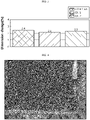
- Each insulating porous layer specimen was impregnated with 10 mL of the electrolyte for 10 minutes, and then a change in width and length of each insulating porous layer was measured to calculate a dimensional change. The results are shown as average values. Referring to FIG.
- Comparative Example 1 shows an increase in length of 2.4 times as compared to the initial length of the insulating porous layer.
- Example 1 and Example 2 show an increase in length of 2.1 times and 2.3 times, respectively. Therefore, it can be seen that Examples 1 and 2 show a lower increase in dimension as compared to Comparative Example 1.
- FIG.4 and FIG. 5 are photographic images illustrating the appearance of Example 3 and that of Example 4, respectively. It can be seen that the insulating porous layers show little change in dimension, and thus the laminated structures maintain their smooth surfaces.
- FIG. 6 is a photographic image illustrating the appearance of the laminated structure according to Comparative Example 2. It can be seen that the insulating porous layer of Comparative Example 2 undergoes a change in dimension to cause deformation of its appearance.
- Each of the insulating porous layer specimens according to Examples and Comparative Example was determined in terms of resistance as follows. LiPF 6 was dissolved in a mixed solvent containing ethylene carbonate, propylene carbonate and propyl propionate at a volume ratio of 25:10:65 to a concentration of 1 M to prepare an electrolyte. Each insulating porous layer specimen was impregnated with the electrolyte and the electrical resistance was measured by using Multi-probe analyzer (Hioki Co.). It can be seen from the following FIG. 2 , that the insulating porous layer specimens according to Examples 1 and 2 show lower resistance as compared to the insulating porous layer specimen according to Comparative Example 1. Referring to FIG. 2 , it can be seen that the insulating porous layers according to Examples 1 and 2 show lower resistance as compared to the insulating porous layer according to Comparative Example 1.
Landscapes
- Chemical & Material Sciences (AREA)
- Chemical Kinetics & Catalysis (AREA)
- Electrochemistry (AREA)
- General Chemical & Material Sciences (AREA)
- Engineering & Computer Science (AREA)
- Power Engineering (AREA)
- Inorganic Chemistry (AREA)
- Composite Materials (AREA)
- Materials Engineering (AREA)
- Microelectronics & Electronic Packaging (AREA)
- Manufacturing & Machinery (AREA)
- Ceramic Engineering (AREA)
- Secondary Cells (AREA)
- Cell Separators (AREA)
Applications Claiming Priority (2)
| Application Number | Priority Date | Filing Date | Title |
|---|---|---|---|
| KR1020190130071A KR102764920B1 (ko) | 2019-10-18 | 2019-10-18 | 전기화학소자용 분리막, 상기 분리막을 포함하는 전기화학소자 및 상기 분리막의 제조방법 |
| PCT/KR2020/014193 WO2021075924A1 (fr) | 2019-10-18 | 2020-10-16 | Membrane de séparation pour dispositif électrochimique, dispositif électrochimique comprenant ladite membrane de séparation, et procédé de fabrication de ladite membrane de séparation |
Publications (2)
| Publication Number | Publication Date |
|---|---|
| EP4033595A1 true EP4033595A1 (fr) | 2022-07-27 |
| EP4033595A4 EP4033595A4 (fr) | 2022-12-21 |
Family
ID=75537917
Family Applications (1)
| Application Number | Title | Priority Date | Filing Date |
|---|---|---|---|
| EP20877495.0A Pending EP4033595A4 (fr) | 2019-10-18 | 2020-10-16 | Membrane de séparation pour dispositif électrochimique, dispositif électrochimique comprenant ladite membrane de séparation, et procédé de fabrication de ladite membrane de séparation |
Country Status (5)
| Country | Link |
|---|---|
| US (1) | US20220384910A1 (fr) |
| EP (1) | EP4033595A4 (fr) |
| KR (1) | KR102764920B1 (fr) |
| CN (1) | CN114514654B (fr) |
| WO (1) | WO2021075924A1 (fr) |
Families Citing this family (5)
| Publication number | Priority date | Publication date | Assignee | Title |
|---|---|---|---|---|
| KR102658662B1 (ko) | 2022-07-07 | 2024-04-17 | 주식회사 엘지에너지솔루션 | 전기화학소자용 분리막 및 상기 분리막의 제조 방법 |
| EP4478517A4 (fr) * | 2022-07-07 | 2025-10-22 | Lg Energy Solution Ltd | Séparateur pour dispositifs électrochimiques et son procédé de fabrication |
| CN116253907A (zh) * | 2022-09-09 | 2023-06-13 | 河北金力新能源科技股份有限公司 | 一种氢化丁腈橡胶浆料及其制备方法和应用 |
| JP2025536040A (ja) * | 2023-05-03 | 2025-10-30 | エルジー エナジー ソリューション リミテッド | 電気化学素子用の自立型分離膜、及びそれを含む電気化学素子 |
| CN121367030A (zh) * | 2025-12-23 | 2026-01-20 | 江苏卓高新材料科技有限公司 | 一种复合涂层隔膜及其制备方法和锂电池 |
Family Cites Families (17)
| Publication number | Priority date | Publication date | Assignee | Title |
|---|---|---|---|---|
| USRE18214E (en) * | 1929-02-11 | 1931-09-29 | Sidney | |
| WO2005011043A1 (fr) * | 2003-07-29 | 2005-02-03 | Matsushita Electric Industrial Co., Ltd. | Accumulateur secondaire aux ions de lithium |
| KR100758482B1 (ko) * | 2004-12-07 | 2007-09-12 | 주식회사 엘지화학 | 표면 처리된 다공성 필름 및 이를 이용한 전기 화학 소자 |
| DE102012000910A1 (de) * | 2012-01-19 | 2013-07-25 | Sihl Gmbh | Separator umfassend eine poröse Schicht und Verfahren zu seiner Herstellung |
| KR20140128421A (ko) * | 2012-02-16 | 2014-11-05 | 솔베이 스페셜티 폴리머스 이태리 에스.피.에이. | 복합 분리막의 제조 방법 |
| HUE048838T2 (hu) * | 2012-11-30 | 2020-08-28 | Lg Chemical Ltd | Elkülönítõ szekunder telephez, amely tartalmazza különbözõ felületi jellemzõkkel bíró szervetlen részecskék kettõs porózus rétegét, az ezt tartalmazó szekunder telep, és eljárás az elkülönítõ elkészítéséhez |
| WO2014147888A1 (fr) * | 2013-03-19 | 2014-09-25 | 帝人株式会社 | Séparateur pour batteries secondaires non aqueuses, et batterie secondaire non aqueuse |
| KR20150060085A (ko) | 2013-11-25 | 2015-06-03 | 쓰리엠 이노베이티브 프로퍼티즈 캄파니 | 재작업성이 우수한 양면 코팅 테이프 |
| KR102234295B1 (ko) * | 2014-01-10 | 2021-03-31 | 삼성에스디아이 주식회사 | 2차전지용 바인더 조성물, 이를 채용한 양극과 리튬전지 |
| KR101707193B1 (ko) * | 2014-04-01 | 2017-02-27 | 주식회사 엘지화학 | 세퍼레이터의 제조방법, 이로부터 형성된 세퍼레이터 및 이를 포함하는 전기화학소자 |
| WO2015196151A1 (fr) * | 2014-06-20 | 2015-12-23 | Amtek Research International Llc | Granules poreux contenant un mélange de poudres de silice et de caoutchouc |
| KR20160002173A (ko) * | 2014-06-30 | 2016-01-07 | 주식회사 엘지화학 | 리튬염을 포함하는 다공성 코팅층을 구비하는 이차 전지용 분리막 및 이의 제조 방법 |
| CN105706270B (zh) * | 2014-10-10 | 2018-05-11 | 住友化学株式会社 | 层叠体、包含层叠体的非水电解液二次电池用间隔件、以及非水电解液二次电池 |
| JP6803913B2 (ja) * | 2016-06-08 | 2020-12-23 | エルジー・ケム・リミテッド | セパレータ及びそれを含む電気化学素子 |
| KR102314215B1 (ko) * | 2016-09-20 | 2021-10-18 | 주식회사 엘지에너지솔루션 | 내열성 및 통기도가 향상된 세퍼레이터 및 이를 포함하는 이차전지 |
| CN108807821B (zh) * | 2018-06-20 | 2021-03-19 | 宁德新能源科技有限公司 | 隔离膜和电化学装置 |
| US20220271288A1 (en) * | 2019-07-10 | 2022-08-25 | Blue Current, Inc. | Argyrodite-containing composites |
-
2019
- 2019-10-18 KR KR1020190130071A patent/KR102764920B1/ko active Active
-
2020
- 2020-10-16 EP EP20877495.0A patent/EP4033595A4/fr active Pending
- 2020-10-16 CN CN202080067210.6A patent/CN114514654B/zh active Active
- 2020-10-16 WO PCT/KR2020/014193 patent/WO2021075924A1/fr not_active Ceased
- 2020-10-16 US US17/760,813 patent/US20220384910A1/en active Pending
Also Published As
| Publication number | Publication date |
|---|---|
| CN114514654B (zh) | 2025-01-21 |
| WO2021075924A1 (fr) | 2021-04-22 |
| CN114514654A (zh) | 2022-05-17 |
| KR20210046405A (ko) | 2021-04-28 |
| EP4033595A4 (fr) | 2022-12-21 |
| US20220384910A1 (en) | 2022-12-01 |
| KR102764920B1 (ko) | 2025-02-06 |
Similar Documents
| Publication | Publication Date | Title |
|---|---|---|
| US20250343322A1 (en) | Separator including polyethylene with highly entangled polymer chains, and electrochemical device including the same | |
| CN116195124B (zh) | 包括粘性层的用于二次电池的隔板和制造其的方法 | |
| KR102225305B1 (ko) | 상분리를 이용하여 무기물 코팅층을 포함하는 분리막을 제조하는 방법 | |
| US20220384910A1 (en) | Separation Membrane for Electrochemical Device, Electrochemical Device Comprising Same Separation Membrane, and Method for Manufacturing Same Separation Membrane | |
| US11929458B2 (en) | Separator having inorganic coating layer including small weight average molecular weight and low melting point PVDF, and method for manufacturing the same | |
| US12148882B2 (en) | Method for fabricating all-solid-state battery including binding electrode portions having electrolyte slurry layer together | |
| US12283716B2 (en) | Separator having heat resistant layer for electrochemical device and secondary battery comprising same | |
| EP3907810A1 (fr) | Batterie secondaire au lithium et procédé de fabrication de batterie secondaire au lithium | |
| EP4203169A1 (fr) | Séparateur pour dispositif électrochimique et son procédé de production | |
| EP3848998A1 (fr) | Séparateur pour dispositif électrochimique, et son procédé de production | |
| KR102830174B1 (ko) | 전기화학소자용 분리막 및 이를 포함하는 전기화학소자 | |
| KR20200047409A (ko) | 용해 온도가 다른 바인더를 포함하는 분리막 및 이의 제조방법 | |
| EP3958344B1 (fr) | Composition de résine liante et séparateur pour dispositif électrochimique la comprenant | |
| JP2023530326A (ja) | 二次電池の製造方法 | |
| KR20170014178A (ko) | 다공성 박막에 전기방사법으로 섬유상 코팅층을 도입한 분리막의 제조 방법 및 이로부터 제조되는 분리막 | |
| US12531311B2 (en) | Separator for electrochemical device, electrochemical device comprising separator and method for preparing separator | |
| KR101410047B1 (ko) | 이차전지용 유무기 다공성분리막의 제조방법 및 이로부터 제조된 유무기 다공성분리막 | |
| KR101491611B1 (ko) | 이차전지용 유무기 다공성분리막의 제조방법 및 이로부터 제조된 유무기 다공성분리막 | |
| KR102563504B1 (ko) | 전기화학소자용 폴리올레핀 분리막 및 이를 구비한 전기화학소자 | |
| EP4322307B1 (fr) | Séparateur pour dispositif électrochimique et dispositif électrochimique le comprenant | |
| EP4007036A1 (fr) | Séparateur pour dispositif électrochimique comprenant une couche résistante à la chaleur, et batterie secondaire le comprenant | |
| KR20230171646A (ko) | 고용량의 전극을 구비하는 리튬 이차전지 | |
| US20250158135A1 (en) | Separator for electrochemical devices and electrochemical device comprising same | |
| CN117882242A (zh) | 制造用于锂二次电池的隔膜的方法,由此制造的用于锂二次电池的隔膜,以及使用该隔膜制造锂二次电池的方法 |
Legal Events
| Date | Code | Title | Description |
|---|---|---|---|
| STAA | Information on the status of an ep patent application or granted ep patent |
Free format text: STATUS: THE INTERNATIONAL PUBLICATION HAS BEEN MADE |
|
| PUAI | Public reference made under article 153(3) epc to a published international application that has entered the european phase |
Free format text: ORIGINAL CODE: 0009012 |
|
| STAA | Information on the status of an ep patent application or granted ep patent |
Free format text: STATUS: REQUEST FOR EXAMINATION WAS MADE |
|
| 17P | Request for examination filed |
Effective date: 20220420 |
|
| AK | Designated contracting states |
Kind code of ref document: A1 Designated state(s): AL AT BE BG CH CY CZ DE DK EE ES FI FR GB GR HR HU IE IS IT LI LT LU LV MC MK MT NL NO PL PT RO RS SE SI SK SM TR |
|
| A4 | Supplementary search report drawn up and despatched |
Effective date: 20221121 |
|
| RIC1 | Information provided on ipc code assigned before grant |
Ipc: H01M 10/052 20100101ALI20221115BHEP Ipc: H01G 11/52 20130101ALI20221115BHEP Ipc: H01M 50/409 20210101AFI20221115BHEP |
|
| DAV | Request for validation of the european patent (deleted) | ||
| DAX | Request for extension of the european patent (deleted) | ||
| STAA | Information on the status of an ep patent application or granted ep patent |
Free format text: STATUS: EXAMINATION IS IN PROGRESS |
|
| 17Q | First examination report despatched |
Effective date: 20250904 |