EP4033858A1 - Induktionsheizgerät und vorrichtung zur steuerung davon - Google Patents
Induktionsheizgerät und vorrichtung zur steuerung davon Download PDFInfo
- Publication number
- EP4033858A1 EP4033858A1 EP22152397.0A EP22152397A EP4033858A1 EP 4033858 A1 EP4033858 A1 EP 4033858A1 EP 22152397 A EP22152397 A EP 22152397A EP 4033858 A1 EP4033858 A1 EP 4033858A1
- Authority
- EP
- European Patent Office
- Prior art keywords
- inverter circuit
- frequency
- duty cycle
- switching
- switching elements
- Prior art date
- Legal status (The legal status is an assumption and is not a legal conclusion. Google has not performed a legal analysis and makes no representation as to the accuracy of the status listed.)
- Granted
Links
Images






Classifications
-
- H—ELECTRICITY
- H05—ELECTRIC TECHNIQUES NOT OTHERWISE PROVIDED FOR
- H05B—ELECTRIC HEATING; ELECTRIC LIGHT SOURCES NOT OTHERWISE PROVIDED FOR; CIRCUIT ARRANGEMENTS FOR ELECTRIC LIGHT SOURCES, IN GENERAL
- H05B6/00—Heating by electric, magnetic or electromagnetic fields
- H05B6/02—Induction heating
- H05B6/06—Control, e.g. of temperature, of power
- H05B6/062—Control, e.g. of temperature, of power for cooking plates or the like
-
- H—ELECTRICITY
- H05—ELECTRIC TECHNIQUES NOT OTHERWISE PROVIDED FOR
- H05B—ELECTRIC HEATING; ELECTRIC LIGHT SOURCES NOT OTHERWISE PROVIDED FOR; CIRCUIT ARRANGEMENTS FOR ELECTRIC LIGHT SOURCES, IN GENERAL
- H05B6/00—Heating by electric, magnetic or electromagnetic fields
- H05B6/02—Induction heating
- H05B6/06—Control, e.g. of temperature, of power
- H05B6/062—Control, e.g. of temperature, of power for cooking plates or the like
- H05B6/065—Control, e.g. of temperature, of power for cooking plates or the like using coordinated control of multiple induction coils
-
- H—ELECTRICITY
- H05—ELECTRIC TECHNIQUES NOT OTHERWISE PROVIDED FOR
- H05B—ELECTRIC HEATING; ELECTRIC LIGHT SOURCES NOT OTHERWISE PROVIDED FOR; CIRCUIT ARRANGEMENTS FOR ELECTRIC LIGHT SOURCES, IN GENERAL
- H05B6/00—Heating by electric, magnetic or electromagnetic fields
- H05B6/02—Induction heating
- H05B6/06—Control, e.g. of temperature, of power
- H05B6/08—Control, e.g. of temperature, of power using compensating or balancing arrangements
-
- H—ELECTRICITY
- H05—ELECTRIC TECHNIQUES NOT OTHERWISE PROVIDED FOR
- H05B—ELECTRIC HEATING; ELECTRIC LIGHT SOURCES NOT OTHERWISE PROVIDED FOR; CIRCUIT ARRANGEMENTS FOR ELECTRIC LIGHT SOURCES, IN GENERAL
- H05B6/00—Heating by electric, magnetic or electromagnetic fields
- H05B6/02—Induction heating
- H05B6/10—Induction heating apparatus, other than furnaces, for specific applications
- H05B6/12—Cooking devices
- H05B6/1209—Cooking devices induction cooking plates or the like and devices to be used in combination with them
- H05B6/1245—Cooking devices induction cooking plates or the like and devices to be used in combination with them with special coil arrangements
Definitions
- an induction heating apparatus Disclosed herein are an induction heating apparatus and a method for controlling the same.
- Induction heating apparatuses are devices that generate eddy current in a metallic container and heat the container, using a magnetic field generated around a working coil.
- alternating current is supplied to the working coil.
- an induced magnetic field is generated around the working coil disposed in the induction heating apparatus.
- magnetic line of force of the induced magnetic field generated passes through a bottom of the metallic container over the working coil, eddy current is generated inside the bottom of the container. Accordingly, the eddy current generated flows in the container, and the container itself is heated.
- FIG. 1 is a view showing a waveform of alternating current supplied to a working coil when a container is heated by an induction heating apparatus of the related art.
- time point P1 is a time point at which a power level of a heating zone of the induction heating apparatus is set, an instruction to initiate heating is input, and current starts to flow in the working coil corresponding to the heating zone.
- an inverter circuit When a user sets a power level and inputs an instruction to initiate heating in a state in which a container is placed in the heating zone, an inverter circuit generates alternating current as a switching signal is supplied to the inverter circuit electrically connected to the working coil, at time point P1. Accordingly, the alternating current generated by the inverter circuit is supplied to the working coil.
- the peak values of the AC current supplied to the working coil until the time point P2 are maintained at IA1 and IA2, respectively. Accordingly, the amount of change in the alternating current supplied to the working coil, i.e., a peak-to-peak value is maintained at IA1-IA2 in the period of P1-P2.
- time point P3 is a time point at which the working coil outputs power having the same value as the required power value.
- a range of the alternating current supplied to the working coil can increase temporarily.
- the peak value of the alternating current supplied to the working coil increases to IA3 greater than IA1 and decreases to IA4 less than IA2.
- a change in the amount of the alternating current supplied to the working coil in the period of P2 ⁇ P3 is IA3-IA4.
- the change of IA3-IA4 is greater than the change of IA1-IA2 of the alternating current supplied to the working coil in the period of P1-P2.
- the peak-to-peak value of the current supplied to the working coil can increase excessively and instantly in the period (e.g., period P2-P3) that is earlier than the time point at which the output power value of the working coil matches the required power value.
- an excessively loud noise can be generated due to an instant increase in the peak-to-peak value of the current supplied to the working coil, as described above.
- the initial driving noise can cause inconvenience to the user each time the user uses the induction heating apparatus, and in some cases, the user can wrongly think that the induction heating apparatus fails.
- a noise suppressing operation may be performed to suppress initial driving noise that can be generated before a frequency for heating a container, i.e., a heating frequency, is determined.
- a controller of an induction heating apparatus in one embodiment may perform the noise suppressing operation by adjusting duty cycles of switching signals input to switching elements included in an inverter circuit and a driving frequency of the inverter circuit respectively.
- the controller may gradually increase duty cycles of switching signals input to switching elements belonging to a first group (e.g., a high side), among the switching elements included in the inverter circuit, from a predetermined first reference duty cycle to a predetermined second reference duty cycle. In another embodiment, the controller may gradually increase a duty cycle of a switching signal input to each of the switching elements included in the inverter circuit.
- a first group e.g., a high side
- the controller may gradually increase a duty cycle of a switching signal input to each of the switching elements included in the inverter circuit.
- the controller may gradually decrease a driving frequency of the inverter circuit from a predetermined first reference frequency to a predetermined second reference frequency.
- magnitude of alternating current supplied to a working coil may gradually increase until an output power value of the working coil becomes identical with a required power value. Accordingly, a temporary increase in the magnitude of the alternating current supplied to the working coil, which would otherwise occur in the related art, may be prevented. Thus, the initial driving noise generated by a working coil in the related art may be suppressed.
- the induction heating apparatus may include a working coil disposed in a position corresponding to a position of a heating zone, an inverter circuit including a plurality of switching elements and configured to supply current to the working coil, a driving circuit configured to supply a switching signal to each of the switching elements included in the inverter circuit, and a controller configured to determine a driving frequency of the inverter circuit, supply a control signal based on the driving frequency to the driving circuit, and drive the working coil.
- the controller may be configured to perform a control method according to any one of the herein described embodiments.
- the controller may be configured to receive an input power level of the heating zone, to adjust duty cycles of switching signals input to the switching elements included in the inverter circuit and a driving frequency of the inverter circuit and to perform a noise suppressing operation, to determine a heating frequency corresponding to the power level, and based on the heating frequency, to supply a switching signal to each of the switching elements included in the inverter circuit and drive the working coil.
- the controller may be additionally or alternatively configured for setting duty cycles of switching signals, input to switching elements belonging to a first group, to a predetermined first reference duty cycle, setting a driving frequency of the inverter circuit to a predetermined first reference frequency, supplying a switching signal to each of the switching elements included in the inverter circuit, based on the first reference duty cycle and the first reference frequency, increasing the duty cycles of the switching signals, supplied to the switching elements belonging to the first group, to a predetermined second reference duty cycle, and decreasing the driving frequency of the inverter circuit to a predetermined second reference frequency.
- the noise suppressing operation may include setting duty cycles of switching signals, input to switching elements belonging to a first group, to a predetermined first reference duty cycle, setting a driving frequency of the inverter circuit to a predetermined first reference frequency, supplying a switching signal to each of the switching elements included in the inverter circuit, based on the first reference duty cycle and the first reference frequency, increasing the duty cycles of the switching signals, supplied to the switching elements belonging to the first group, to a predetermined second reference duty cycle, and decreasing the driving frequency of the inverter circuit to a predetermined second reference frequency.
- duty cycles of switching signals input to switching elements belonging to a second group may be set to a predetermined third reference duty cycle.
- the third reference duty cycle may be set to a duty cycle the same as the second reference duty cycle.
- the noise suppressing operation may include setting a duty cycle of a switching signal, input to each of the switching elements included in the inverter circuit, to a predetermined first reference duty cycle, setting a driving frequency of the inverter circuit to a predetermined first reference frequency, supplying a switching signal to each of the switching elements included in the inverter circuit, based on the first reference duty cycle and the first reference frequency, increasing a duty cycle of a switching signal supplied to each of the switching elements included in the inverter circuit to a predetermined second reference duty cycle, and decreasing the driving frequency of the inverter circuit to a predetermined second reference frequency.
- the controller may compare an output power value of the working coil with a required power value while decreasing the driving frequency of the inverter circuit, and determine a driving frequency at a time when the output power value matches the required power value as the heating frequency.
- the required power value may correspond to the input power level.
- a method for controlling an induction heating apparatus may include receiving an input power level of a heating zone, performing a noise suppressing operation by adjusting duty cycles of switching signals input to switching elements included in an inverter circuit and a driving frequency of the inverter circuit, determining a heating frequency corresponding to the power level, and driving a working coil by supplying a switching signal to each switching element included in the inverter circuit, based on the heating frequency.
- Performing the noise suppressing operation may include setting duty cycles of switching signals, input to switching elements belonging to a first group, to a predetermined first reference duty cycle, setting a driving frequency of the inverter circuit to a predetermined first reference frequency, supplying a switching signal to each of the switching elements included in the inverter circuit, based on the first reference duty cycle and the first reference frequency, increasing the duty cycles of the switching signals, supplied to the switching elements belonging to the first group, to a predetermined second reference duty cycle, and decreasing the driving frequency of the inverter circuit to a predetermined second reference frequency.
- duty cycles of switching signals input to switching elements belonging to a second group may be set to a predetermined third reference duty cycle.
- the third reference duty cycle may be set to a duty cycle the same as the second reference duty cycle.
- Performing the noise suppressing operation may include setting a duty cycle of a switching signal, input to each of the switching elements included in the inverter circuit, to a predetermined first reference duty cycle, setting a driving frequency of the inverter circuit to a predetermined first reference frequency, supplying a switching signal to each of the switching elements included in the inverter circuit, based on the first reference duty cycle and the first reference frequency, increasing a duty cycle of a switching signal supplied to each of the switching elements included in the inverter circuit to a predetermined second reference duty cycle, and decreasing the driving frequency of the inverter circuit to a predetermined second reference frequency.
- Determining a heating frequency corresponding to the power level may include comparing an output power value of the working coil with a required power value while decreasing the driving frequency of the inverter circuit, and determining a driving frequency at a time when the output power value matches the required power value as the heating frequency.
- the required power value may correspond to the input power level.
- initial driving noise when a power level of a heating zone is set and a container starts to be heated, initial driving noise may be reduced.
- a user may experience no inconvenience caused by noise while using an induction heating apparatus and user satisfaction may improve. Additionally, the possibility that the user misunderstood that the induction heating device is malfunctioning due to the initial driving noise is lowered.
- FIG. 2 is an exploded perspective view showing an induction heating apparatus in one embodiment.
- an induction heating apparatus 10 in one embodiment may include a case 102 constituting a main body, and a cover plate 104 coupled to the case 102 and sealing the case 102.
- the cover plate 104 may be coupled to an upper surface of the case 102 and seal a space, formed inside the case 102, from the outside.
- the cover plate 104 may include an upper plate 106 on which a container for cooking a food item is placed.
- the upper plate 106 may be made of tempered glass such as ceramic glass.
- a material for the upper plate 106 may vary depending on embodiments.
- Heating zones 12, 14 respectively corresponding to working coil assemblies 122, 124 may be formed on the upper plate 106.
- lines or figures corresponding to the heating zones 12, 14 may be printed or displayed on the upper plate 106.
- the case 102 may be formed into a cuboid, an upper portion of which is open.
- the working coil assemblies 122, 124 for heating a container may be disposed in the space formed inside the case 102.
- an interface 114 may be disposed inside the case 102, and the interface 114 may allow the user to supply power or be used to adjust a power level of each of the heating zones 12, 14, and display information on the induction heating apparatus 10.
- the interface 114 may be implemented as a touch panel that is capable of inputting and displaying information at the touch of the touch panel. However, an interface 114 having a different structure may be used depending on embodiments.
- a manipulation zone 118 may be disposed in a position corresponding to a position of the interface 114.
- characters or images and the like may be printed in the manipulation zone 118, in advance.
- the user may perform desired manipulation by touching a specific point of the manipulation zone 118 with reference to the characters or images that are printed in the manipulation zone 118 in advance.
- information output by the interface 114 may be displayed through the manipulation zone 118.
- the user may set a power level of each of the heating zones 12, 14 through the interface 114.
- the power level may be displayed in the manipulation zone 118 as numbers (e.g., 1, 2, 3, ..., 9).
- a required power value and a heating frequency of a working coil corresponding to each of the heating zones 12, 14 may be determined.
- a controller may drive each working coil, based on the determined heating frequency, such that an actual output power value of each working coil matches a required power value set by the user.
- a power supply 112 for supplying power to the working coil assemblies 122, 124 or the interface 114 may be disposed in the space formed inside the case 102.
- two working coil assemblies i.e., a first working coil assembly 122 and a second working coil assembly 124
- a first working coil assembly 122 and a second working coil assembly 124 are disposed inside the case 102, for example.
- three or more working coil assemblies may be disposed inside the case 102, depending on embodiments.
- the working coil assemblies 122, 124 may include a working coil that forms an induced magnetic field using a high-frequency alternating current supplied by the power supply unit 112, and an insulating sheet for protecting a coil from heat generated by a working coil forming an induced magnetic field.
- the first working coil assembly 122 may include a first working coil 132 for heating a container placed in a first heating zone 12, and a first insulating sheet 130, for example.
- the second working coil assembly 124 may include a second working coil and a second insulating sheet. Depending on embodiments, the insulating sheet may not be provided.
- each of the working coils may be provided with a temperature sensor, in a central portion thereof.
- a temperature sensor 134 may be disposed in a central portion of the first working coil 132, for example.
- the temperature sensor may measure a temperature of a container placed in each of the heating zones.
- the temperature sensor may be a thermistor temperature sensor having a variable resistance whose resistance value changes according to the temperature of the container, but the type of the temperature sensor is not limited thereto.
- the temperature sensor may output a sensing voltage corresponding to a temperature of a container, and the sensing voltage output from the temperature sensor may be delivered to the controller.
- the controller may ascertain the temperature of the container, based on magnitude of the sensing voltage output from the temperature sensor, and when the temperature of the container is a predetermined reference value or greater, may perform an overheat preventing operation by decreasing an actual power value of a working coil or stopping driving of a working coil.
- a substrate may be disposed in the space formed inside the case 102, and a plurality of circuits or elements including the controller may be mounted onto the substrate.
- the controller may drive each of the working coils according to the user's instruction to initiate heating, input through the interface 114, to perform a heating operation.
- the controller may stop the driving of the working coils to end the heating operation.
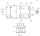
- FIG. 3 is a circuit diagram of the induction heating apparatus in one embodiment.
- the induction heating apparatus 10 in one embodiment may include a rectifying circuit 202, smoothing circuits LI, C1, an inverter circuit 204, a working coil 132, a controller 2, and a driving circuit 22.
- the rectifying circuit 202 may include a plurality of diode elements D1, D2, D3, D4.
- the rectifying circuit 202 may be a bridge diode circuit, as illustrated in FIG.3 , and may be another circuit depending on embodiments.
- the rectifying circuit 202 may rectify AC voltage supplied by a power supplying device 20 and output voltage having a pulse waveform.
- the smoothing circuits LI, C1 may smooth the voltage rectified by the rectifying circuit 202 and output DC link voltage.
- the smoothing circuits LI, C1 may include a first inductor L1 and a DC link capacitor C1.
- the inverter circuit 204 may include a first switching element SW1, a second switching element SW2, a third switching element SW3, and a fourth switching element SW4.
- the inverter circuit 204 of the induction heating apparatus 10 in one embodiment may be implemented as a full-bridge circuit including four switching elements SW1, SW2, SW3, SW4. In another embodiment, the inverter circuit 204 may be implemented as a half-bridge circuit including two switching elements (i.e., a first switching element SW1 and a second switching element SW2 in FIG. 3 ).
- the first switching element SW1, the second switching element SW2, the third switching element SW3 and the fourth switching element SW4 may be respectively turned on and turned off by a first switching signal S1, a second switching signal S2, a third switching signal S3 and a fourth switching signal S4.
- Each of the switching elements SW1, SW2, SW3, SW4 may be turned on when each of the switching signals S1, S2, S3, S4 is at a high level, and turned off when each of the switching signals S1, S2, S3, S4 is at a low level.
- each of the switching elements SW1, SW2, SW3, SW4 is an IGBT element, for example.
- each of the switching elements SW1, SW2, SW3, SW4 may be another type of switching element (e.g., a BJT or an FET and the like), depending on embodiments.
- any of the switching elements SW1, SW2, SW3, SW4 may be turned on and turned off complementarily.
- the second switching element SW2 may be turned off (turned on) while the first switching element SW1 is turned on (turned off).
- the switching elements that are turned on and turned off complementarily are referred to as 'complementary' switching elements.
- any of the switching elements SW1, SW2, SW3, SW4 may be turned on and turned off identically.
- the first switching element SW1 and the third switching element SW3 may be turned on and turned off with the same timing.
- the switching elements that are turned on and turned off with the same timing are referred to as switching elements' belonging to the same group'.
- the first switching element SW1 and the third switching element SW3 are referred to as switching elements belonging to a first group, i.e., a high side
- the second switching element SW2 and the fourth switching element SW4 are referred to as switching elements belonging to a second group, i.e., a low side.
- the inverter circuit 204 is implemented as a half-bridge circuit, i.e., a circuit only including the first switching element SW1 and the second switching element SW2 in another embodiment, the first switching element SW1 may be a switching element belonging to the first group, and the second switching element SW2 may be a switching element belonging to the second group.
- DC link voltage input to the inverter circuit 204 may be converted into alternating current as a result of the turn-on and turn-off operations, i.e., a switching operation, of the switching elements SW1, SW2, SW3, SW4 included in the inverter circuit 204.
- the alternating current converted by the inverter circuit 204 may be supplied to the working coil 132. As a resonance phenomenon occurs in the working coil 132, eddy current may flow in a container, and the container may be heated.
- each of the first switching element S1, the second switching element S2, the third switching element S3 and the fourth switching element S4 may be a pulse width modulation (PWM) signal having a predetermined duty cycle.
- PWM pulse width modulation
- the working coil 132 When the alternating current output from the inverter circuit 204 is supplied to the working coil 132, the working coil 132 may be driven. As a result of the driving of the working coil 132, a container placed over the working coil 132 may be heated while eddy current flows in the container. During the driving of the working coil 132, magnitude of thermal energy supplied to the container may vary depending on magnitude of power actually generated as a result of the driving of the working coil, i.e., an actual output power value of the working coil.
- the induction heating apparatus 10 When the induction heating apparatus 10 is powered on as a result of manipulation of the interface of the induction heating apparatus 10 by the user, the induction heating apparatus may be put on standby for driving as power is supplied to the induction heating apparatus from an input power supply 20. Then the user may place a container over a working coil of the induction heating apparatus and set a power level for the container, to give the working coil an instruction to initiate heating. When the instruction to initiate heating is given by the user, a power value required of the working coil 132, i.e., a required power value of the working coil 132 may be determined based on the power level set by the user.
- the controller 2 may determine a frequency, i.e., a heating frequency, corresponding to the required power value of the working coil 132, and supply a control signal corresponding to the determined heating frequency to the driving circuit 22. Accordingly, the switching signals S1, S2, S3, S4 may be output from the driving circuit 22, and as the switching signals S1, S2, S3, S4 are respectively input to the switching elements SW1, SW2, SW3, SW4, the working coil 132 may be driven. As a result of the driving of the working coil 132, the container may be heated while eddy current flows in the container.
- a frequency i.e., a heating frequency
- the controller 2 may determine a heating frequency that is a frequency corresponding to a power level of a heating zone set by the user. For example, when the user sets a power level of a heating zone, the controller 2 may gradually decrease a driving frequency of the inverter circuit 204, in a state in which the driving frequency of the inverter circuit 204 is set to a predetermined reference frequency, until an output power value of the working coil 132 matches a required power value corresponding to the power level set by the user. The controller 2 may determine a frequency at a time when the output power value of the working coil 132 matches the required power value as a heating frequency.
- the controller 2 may supply a control signal corresponding to the determined heating frequency to the driving circuit 22.
- the driving circuit 22 may output switching signals S1, S2, S3, S4 that have a duty ratio corresponding to the heating frequency determined by the controller 2, based on the control signal output from the controller 2.
- switching signals S1, S2, S3, S4 alternating current may be supplied to the working coil 132 while the switching elements SW1, SW2, SW3, SW4 are turned on and turned off complementarily.
- the controller 2 may perform a noise suppressing operation for suppressing an initial driving noise before the heating frequency is determined.
- a process in which the controller 2 of the induction heating apparatus 10 performs a noise suppressing operation and a process in which a heating frequency of the inverter circuit 204 is determined are specifically described.
- FIG. 4 is a graph showing a relationship between a driving frequency of an inverter circuit and an output power value of a working coil in one embodiment.
- FR denotes a resonance frequency of the inverter circuit 204.
- the driving frequency of the inverter circuit 204 may be determined as a value greater than the resonance frequency FR.
- PR denotes a required power value corresponding to a power level set for a heating zone
- FH denotes a driving frequency, i.e., a heating frequency, of the inverter circuit 204 when an output power value of the working coil 132 matches the required power value PR.
- the controller 2 may perform a noise suppressing operation.
- the controller 2 may set a driving frequency of the inverter circuit 204 to a predetermined first driving frequency F1.
- the first driving frequency F1 may be set to 120 kHz.
- the first driving frequency F1 may be set to different values depending on embodiments.
- an output power value P1 of the working coil 132 may be much lower than the required power value PR. Accordingly, a container may hardly be heated. It means that a peak-to-peak value of current output from the inverter circuit 204 is very low when the driving frequency of the inverter circuit 204 is set to the first driving frequency F1. When the driving frequency of the inverter circuit 204 is set to the first driving frequency F1, noise, caused by the driving of the working coil 132, may be minimized.
- the controller 2 may supply switching signals S1, S2, S3, S4 to the inverter circuit 204. Then the controller 2 may gradually decrease the driving frequency of the inverter circuit 204 by a predetermined unit size (e.g., 1 kHz) until the driving frequency of the inverter circuit 204 reaches to a second driving frequency F2.
- a predetermined unit size e.g. 1 kHz
- the second driving frequency F2 may be set to 60 kHz.
- the second driving frequency F2 may be set to different values depending on embodiments.
- an output power value P2 of the working coil 132 may be much lower than the required power value PR. Accordingly, the container may hardly be heated. It means that a peak-to-peak value of current output from the inverter circuit 204 is very low when the driving frequency of the inverter circuit 204 is set to the second driving frequency F2. Accordingly, although the driving frequency of the inverter circuit 204 decreases to the second driving frequency F2, noise, caused by the driving of the working coil 132, may still be minimized.
- the noise suppressing operation for suppressing an initial driving noise of the working coil 132 may be performed by decreasing the driving frequency of the inverter circuit 204 from the first driving frequency F1 to the second driving frequency F2.
- the controller 2 may determine a heating frequency corresponding to the power level that is input by the user to heat the container.
- the controller 2 may gradually decrease the driving frequency of the inverter circuit 204 by a predetermined unit size (e.g., 1 kHz) while comparing the output power value of the working coil 132 with the required power value PR in the state in which the driving frequency of the inverter circuit 204 is set to the second driving frequency F2.
- the controller 2 may determine a driving frequency at a time when the output power value of the working coil 132 matches the required power value PR as a heating frequency FH.
- the controller 2 may supply a control signal corresponding to the heating frequency FH to the driving circuit 22.
- the driving circuit 22 may supply switching signals S1, S2, S3, S4 corresponding to the heating frequency FH to the inverter circuit 204, and the working coil 132 may output power having a value the same as the required power value PR to heat the container using current supplied by the inverter circuit 204 .
- the noise suppressing operation performed by the controller 2 may include below-described control of a duty cycle of a switching signal as well as the above-described control of a driving frequency of the inverter circuit 204.
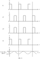
- FIG. 5 is a view showing a waveform of each of the switching signals and a waveform of current supplied to the working coil when duty cycles of the switching signals input to switching elements belonging to a first group are set to 0.05, in one embodiment.
- FIG. 6 is a view showing a waveform of each of the switching signals and a waveform of current supplied to the working coil when the duty cycles of the switching signals input to the switching elements belonging to the first group are set to 0.25, in one embodiment.
- FIG. 7 is a view showing a waveform of each of the switching signals and a waveform of current supplied to the working coil when the duty cycles of the switching signals input to the switching elements belonging to the first group are set to 0.5, in one embodiment.
- FIGS. 5 to 7 show a waveform of each of the switching signals S1, S2, S3, S4 output by the driving circuit 22. Additionally, FIGS. 5 to 7 show a waveform of current supplied to the working coil 132 when each of the switching signals S1, S2, S3, S4 is supplied to each of the switching elements SW1, SW2, SW3, SW4 of the inverter circuit 204.
- the controller 2 may perform a noise suppressing operation.
- the controller 2 may adjust duty cycles of the switching signals S1, S3 input to some of the switching elements SW1, SW2, SW3, SW4 included in the inverter circuit 204, e.g., the switching elements SW1 and SW3 belonging to the first group.
- the duty cycles of the switching signals S1, S3 input to the switching elements SW1 and SW3 belonging to the first group are adjusted, is described.
- duty cycles of the switching signals S2, S4 input to the switching elements SW2, SW4 belonging to the second group may be adjusted.
- a duty cycle of a switching signal is defined as a ratio (T1/T12) of on-time T1 to a total of on-time T1 and off-time T2 of the switching signal, i.e., a single cycle time of the switching signal.
- the controller 2 may set duty cycles of the switching signals S1, S3, input to the switching elements SW1 and SW3 belonging to the first group, to a predetermined first reference duty cycle, e.g., 0.05 (see FIG. 5 ). Then the controller 2 may increase the duty cycles of the switching signals S1, S3 input to the switching elements SW1 and SW3 belonging to the first group by a predetermined unit size (e.g., 0.01) until the duty cycles of the switching signals S1, S3 input to the switching elements SW1 and SW3 belonging to the first group increase to a second reference duty cycle (e.g., 0.5).
- the first reference duty cycle may be set to different values depending on embodiments.
- FIG. 6 shows wave forms of the switching signals when the duty cycles of the switching signals S1, S3 input to the switching elements SW1 and SW3 belonging to the first group increase to 0.25
- FIG. 7 shows wave forms of the switching signals when the duty cycles of the switching signals S1, S3 input to the switching elements SW1 and SW3 belonging to the first group increase to the second reference duty cycle (e.g. 0.5).
- the second reference duty cycle may be set to different values depending on embodiments.
- the duty cycles of the switching signals S2, S4 input to the switching elements SW2 and SW4 belonging to the second group may be fixed to the second reference duty cycle (e.g., 0.5).
- the duty cycles of the switching signals S2, S4 input to the switching elements SW2 and SW4 belonging to the second group may be set to different values depending on embodiments.
- a range (a peak-to-peak value) of alternating current supplied to the working coil 132 may gradually increase, as the duty cycles of the switching signals S1, S3 input to the switching elements SW1and SW3 belonging to the first group gradually increase from the first reference duty cycle (e.g., 0.05) to the second reference duty cycle (e.g., 0.5).
- the peak-to-peak value of the alternating current supplied to the working coil 132 may gradually increase to IA1-IA2, IA3-IA4, and IA5-IA6 respectively.
- alternating current having a peak-to-peak value may not be instantaneously supplied to the working coil 132 during an initial driving process of the working coil 132, and the peak-to-peak value of the current supplied to the working coil 132 may gradually increase, unlike that of the related art. Accordingly, during the initial driving process of the working coil 132, the peak-to-peak value of the current supplied to the working coil 132 may be prevented from increasing excessively and instantly, and an initial driving noise may not be made.
- FIG. 8 is a view showing a waveform of each switching signal and a waveform of current supplied to the working coil when the duty cycle of the switching signal input to each switching element is set to 0.05, in one embodiment.
- FIG. 9 is a view showing a waveform of each switching signal and a waveform of current supplied to the working coil when the duty cycle of the switching signal input to each switching element is set to 0.25, in one embodiment.
- FIG. 10 is a view showing a waveform of each switching signal and a waveform of current supplied to the working coil when the duty cycle of the switching signal input to each switching element is set to 0.5, in one embodiment.
- FIGS. 8 to 10 show a waveform of each of the switching signals S1, S2, S3, S4 output by the driving circuit 22. Additionally, FIGS. 8 to 10 show a waveform of current supplied to the working coil 132 when each of the switching signals S1, S2, S3, S4 is supplied to each of the switching elements SW1, SW2, SW3, SW4 of the inverter circuit 204.
- the controller 2 may adjust the duty cycle of the switching signal S1, S2, S3, S4 input to each of the switching elements SW1, SW2, SW3, SW4 included in the inverter circuit 204, as illustrated in FIGS. 8 to 10 .
- the controller 2 may set the duty cycle of the switching signal S1, S2, S3, S4, input to each of the switching elements SW1, SW2, SW3, SW4, to a predetermined first reference duty cycle, e.g., 0.05 (see FIG. 8 ). Then the controller 2 may increase the duty cycle of the switching signal S1, S2, S3, S4 input to each of the switching elements SW1, SW2, SW3, SW4 by a predetermined unit size (e.g., 0.01) until the duty cycle of the switching signal S1, S2, S3, S4 input to each of the switching elements SW1, SW2, SW3, SW4 increases to a second reference duty cycle (e.g., 0.5).
- the first reference duty cycle may be set to different values depending on embodiments.
- FIG. 9 shows waveforms of the switching signals when the duty cycle of the switching signal S1, S2, S3, S4 input to each of the switching elements SW1, SW2, SW3, SW4 increases to 0.25
- FIG. 10 shows waveforms of the switching signals when the duty cycle of the switching signal S1, S2, S3, S4 input to each of the switching elements SW1, SW2, SW3, SW4 increases to the second reference duty cycle (e.g., 0.5).
- a range (a peak-to-peak value) of alternating current supplied to the working coil 132 may gradually increase as the duty cycle of the switching signal S1, S2, S3, S4 input to each of the switching elements SW1, SW2, SW3, SW4 gradually increases from the first reference duty cycle (e.g., 0.05) to the second reference duty cycle (e.g., 0.5).
- the peak-to-peak value of the alternating current supplied to the working coil 132 may gradually increase to IA7-IA8, IA9-IA10 and IA11-IA12 respectively.
- alternating current having a peak-to-peak value may not be instantaneously supplied to the working coil 132 during an initial driving process of the working coil 132, and the peak-to-peak value of the current supplied to the working coil 132 may gradually increase, unlike that of the related art. Accordingly, during the initial driving process of the working coil 132, the peak-to-peak value of the current supplied to the working coil 132 may be prevented from increasing excessively and instantly, and an initial driving noise may not be made.
- FIG. 11 is a flow chart showing a method for controlling an induction heating apparatus in one embodiment.
- a controller 2 of an induction heating apparatus 10 may receive an input power level of a heating zone formed on an upper plate of the induction heating apparatus 10 (1102). When the power level of the heating zone is input, a required power value of a working coil corresponding to the heating zone may be determined.
- the controller 2 may adjust a duty cycle of a switching signal input to a switching element included in an inverter circuit 204 and a driving frequency of the inverter circuit 204, and perform a noise suppressing operation (1104).
- the noise suppressing operation performed by the controller 2 may include setting duty cycles of switching signals, input to switching elements belonging to a first group, to a predetermined first reference duty cycle, setting a driving frequency of the inverter circuit 204 to a predetermined first reference frequency, supplying a switching signal to each of the switching elements included in the inverter circuit 204, based on the first reference duty cycle and the first reference frequency, increasing the duty cycles of the switching signals, supplied to the switching elements belonging to the first group, to a predetermined second reference duty cycle, and decreasing the driving frequency of the inverter circuit 204 to a predetermined second reference frequency.
- duty cycles of switching signals input to switching elements belonging to a second group may be set to a predetermined third reference duty cycle.
- the third reference duty cycle may be set to a duty cycle the same as the second reference duty cycle.
- the noise suppressing operation performed by the controller 2 may include setting a duty cycle of a switching signal, input to each of the switching elements included in the inverter circuit 204, to a predetermined first reference duty cycle, setting a driving frequency of the inverter circuit 204 to a predetermined first reference frequency, supplying a switching signal to each of the switching elements included in the inverter circuit 204, based on the first reference duty cycle and the first reference frequency, increasing a duty cycle of a switching signal supplied to each of the switching elements included in the inverter circuit 204 to a predetermined second reference duty cycle, and decreasing the driving frequency of the inverter circuit 204 to a predetermined second reference frequency.
- the controller 2 may determine a heating frequency corresponding to the power level previously input (1106).
- determining a heating frequency corresponding to the power level (1106) may include comparing an output power value of the working coil 132 with the required power value while decreasing the driving frequency of the inverter circuit 204, and determining a driving frequency at a time when the output power value matches the required power value as the heating frequency.
- the controller 2 may drive the working coil 132 by supplying a switching signal to each switching element included in the inverter circuit 204, based on the determined heating frequency (1108).
- FIG. 12 is a flow chart showing a method for controlling an induction heating apparatus in another embodiment.
- the user may input a power level of the heating zone, in which the container to be heated is placed, through a manipulation zone 118 of the induction heating apparatus 10. Accordingly, the controller 2 may receive the input power level of the heating zone (1202). When the power level of the heating zone is input, the controller 2 may calculate an output power value corresponding to the input power level, and determine the calculated output power value as a required power value of a working coil 132 corresponding to the heating zone.
- the controller 2 may perform a noise suppressing operation including steps 1204 to 1214, to suppress initial driving noise that is generated before the working coil 132 starts to heat the container.
- the controller 12 may set duty cycles of switching signals input to switching elements belonging to a first group to a first reference duty cycle (1204). For example, the controller 2 may set the duty cycles of the switching signals S1, S3, input to the switching elements SW1, SW3 belonging to the first group, to a predetermined first reference duty cycle (e.g., 0.05), in the circuit illustrated in FIG. 3 .
- a predetermined first reference duty cycle e.g., 0.05
- the controller 2 may set a driving frequency of the inverter circuit 204 to a predetermined first reference frequency (1206).
- the controller 2 may set the driving frequency of the inverter circuit 204 to the predetermined first reference frequency (e.g., 120 kHz), in the circuit illustrated in FIG. 3 .
- the controller 2 may supply a switching signal to each of the switching elements included in the inverter circuit, based on the first reference duty cycle set in step 1204 and the first reference frequency set in step 1206 (1208). Accordingly, alternating current generated from the inverter circuit may be supplied to the working coil.
- the controller 2 may determine whether the duty cycles of the switching signals input to the switching elements belonging to the first group are the same as a predetermined second reference duty cycle (e.g., 0.5) (1210).
- a predetermined second reference duty cycle e.g., 0.5
- the controller 2 may increase the duty cycles of the switching signals input to the switching elements belonging to the first group by a predetermined unit size (e.g., 0.01) (1212). As a result of repetition of step 1210 and step 1212, the duty cycles of the switching signals input to the switching elements belonging to the first group may gradually increase from the first reference duty cycle to the second reference duty cycle.
- a predetermined unit size e.g., 0.01
- FIG. 12 shows an embodiment in which the duty cycles of the switching signals input to the switching elements belonging to the first group gradually increase from the first reference duty cycle to the second reference duty cycle.
- duty cycles of switching signals input to all the switching elements included in the inverter circuit 204 may gradually increase from the first reference duty cycle to the second reference duty cycle.
- the controller 2 may determine whether the driving frequency of the inverter circuit is the same as a predetermined second reference frequency (e.g., 60 kHz) (1214).
- a predetermined second reference frequency e.g. 60 kHz
- the controller 2 may decrease the driving frequency of the inverter circuit by a predetermined unit size (e.g., 1 kHz) (1216). As a result of repetition of step 1214 and step 1216, the driving frequency of the inverter circuit may gradually decrease from the first reference frequency to the second reference frequency.
- a predetermined unit size e.g. 1 kHz
- the noise suppressing operation may end.
- the controller 2 may determine a heating frequency corresponding to the power level input in step 1202 (1218). For example, the controller 2 may compare the output power value of the working coil 132 with the required power value while decreasing the driving frequency of the inverter circuit 204 by a predetermined unit size (e.g., 1 kHz) from the second reference frequency (e.g., 60 kHz). The controller 2 may determine a driving frequency at a time when the output power value of the working coil 132 matches the required power value as a frequency for heating the container, i.e., a heating frequency.
- a predetermined unit size e.g. 1 kHz
- the second reference frequency e.g. 60 kHz
- the controller 2 may supply a switching signal to each of the switching elements included in the inverter circuit, based on the heating frequency (1220).
- a duty cycle of a switching signal S1, S2, S3, S4 supplied to each of the switching elements may be set to the same duty cycle. Accordingly, while alternating current output from the inverter circuit is supplied to the working coil 132, the working coil 132 may output power having the same value as the required power value, and the container may be heated.
- the driving frequency of the inverter circuit may be adjusted after the duty cycles of the switching signals input to the inverter circuit is adjusted.
- the duty cycles of the switching signals may be adjusted after the driving frequency of the inverter circuit is adjusted.
- the duty cycles of the switching signals and the driving frequency of the inverter circuit may be adjusted at the same time.
- FIG. 13 is a graph showing changes in a driving frequency of an inverter circuit and a duty cycle of a switching signal when the working coil is driven at a high power level in one embodiment.
- data 1301 indicates a driving frequency of the inverter circuit
- data 1302 indicates a duty cycle of a switching signal input to the switching elements of the inverter circuit.
- the working coil may be driven at a high power level (e.g., a power level of 4 or more among power levels of 1 to 9).
- a high power level e.g., a power level of 4 or more among power levels of 1 to 9.
- a first section A1 is a section in which the driving of the working coil is started according to an instruction to initiate heating input by the user.
- the driving frequency of the inverter circuit is set to a predetermined first reference frequency FR1 (e.g., 120 kHz).
- the duty cycle of the switching signal input to the inverter circuit in the first section A1 increases from a predetermined first reference duty cycle DR1 (e.g., 10%) to a second reference duty cycle DR2 (e.g., 50%). That is, the noise suppressing operation is performed in the first section A1 to suppress noise generated during the initial driving of the working coil.
- the driving frequency of the inverter circuit decreases from the first reference frequency FR1 to a predetermined second reference frequency FR2 (e.g., 80 kHz).
- the controller 2 determines the heating frequency FH corresponding to the power level input by the user. Also, in the third section A3, the controller 2 may perform a container detection operation for determining whether a heatable container exists above the working coil based on the resonance current value of the working coil.
- the driving frequency of the inverter circuit decreases from the second reference frequency FR2 to the heating frequency FH (e.g., 40 kHz). Accordingly, the output power value of the working coil gradually increases.
- FH heating frequency
- the inverter circuit is driven at the heating frequency FH. Accordingly, the container is heated to correspond to the power level set by the user.
- the duty cycle of the switching signal input to the inverter circuit in the second section A2 to the fifth section A5 is maintained as the second reference duty cycle DR2.
- noise generated during the initial driving of the working coil is reduced compared to the related art by the noise suppressing operation performed in the first section A1.
- the driving frequency of the inverter circuit is gradually adjusted to the heating frequency FH from the first reference frequency FR1 and the second reference frequency FR2, noise due to a sudden change in the driving frequency does not occur.
- FIG. 14 is a graph showing changes in a driving frequency of an inverter circuit and a duty cycle of a switching signal when the working coil is driven at a low power level in one embodiment.
- data 1401 and 1403 indicate driving frequencies of the inverter circuit
- data 1402 and 1404 indicate duty cycles of switching signals input to the switching elements of the inverter circuit.
- the working coil may be driven at a low power level (e.g., a power level of 3 or less among power levels of 1 to 9).
- a low power level e.g., a power level of 3 or less among power levels of 1 to 9.
- the working coil is discontinuously driven until heating is finished, that is, in an on/off manner.
- the driving of the working coil is controlled so that the on sections (ON1, ON2) in which the working coil is driven and the off sections (OFF1, OFF2) in which the working coil is not driven appear alternately.
- the controller 2 may control the driving of the working coil so that the average value of the output power values of the working coils accumulated in each of the on sections ON1 and ON2 respectively correspond to the required power value.
- the power level values belonging to the high power level and the power level values belonging to the low power level may vary according to embodiments.
- the first on section ON1 includes the first section A1 to the fourth section A4.
- the first section A1 is a section in which the driving of the working coil is started according to an instruction to initiate heating input by the user.
- the driving frequency of the inverter circuit is set to a predetermined first reference frequency FR1 (e.g., 120 kHz).
- the duty cycle of the switching signal input to the inverter circuit in the first section A1 is increases from a predetermined first reference duty cycle DR1 (e.g., 10%) to a second reference duty cycle DR2 (e.g., 50%). That is, the noise suppressing operation is performed in the first section A1 to suppress noise generated during the initial driving of the working coil.
- a predetermined first reference duty cycle DR1 e.g. 10%
- a second reference duty cycle DR2 e.g. 50%
- the driving frequency of the inverter circuit decreases from the first reference frequency FR1 to the second predetermined reference frequency FR2.
- the controller 2 determines the heating frequency FH corresponding to the power level input by the user.
- the heating frequency FH e.g., 50 kHz
- the controller 2 may perform a container detection operation for determining whether a heatable container exists above the working coil based on the resonance current value of the working coil.
- the driving frequency of the inverter circuit is maintained at the heating frequency FH, that is, the second reference frequency FR2.
- the duty cycle of the switching signal input to the inverter circuit in the second section A2 to the fourth section A4 is maintained as the second reference duty cycle DR2.
- the second on section ON2 includes a first section A1 to a fourth section A4.
- the driving process of the working coil in the first section A1 to the fourth section A4 included in the second on section ON2 is as same as the driving process of the working coil in the first section A1 to the fourth section included in the first on section ON1.
- the working coil is driven so that the on section and the off section appear alternately even after the second off section OFF2.
- the noise suppressing operation is performed in the first section A1 whenever each of the ON sections ON1 and ON2 starts. Therefore, whenever the ON section starts, noise generated due to the initial driving of the working coil is reduced compared to the related art.
- the driving frequency of the inverter circuit is gradually adjusted from the first reference frequency FR1 to the heating frequency FH, noise due to a sudden change in the driving frequency does not occur.
Landscapes
- Physics & Mathematics (AREA)
- Electromagnetism (AREA)
- General Induction Heating (AREA)
Applications Claiming Priority (2)
| Application Number | Priority Date | Filing Date | Title |
|---|---|---|---|
| KR20210008193 | 2021-01-20 | ||
| KR1020220006854A KR102941295B1 (ko) | 2021-01-20 | 2022-01-17 | 유도 가열 장치 및 유도 가열 장치의 제어 방법 |
Publications (2)
| Publication Number | Publication Date |
|---|---|
| EP4033858A1 true EP4033858A1 (de) | 2022-07-27 |
| EP4033858B1 EP4033858B1 (de) | 2023-12-06 |
Family
ID=80113251
Family Applications (1)
| Application Number | Title | Priority Date | Filing Date |
|---|---|---|---|
| EP22152397.0A Active EP4033858B1 (de) | 2021-01-20 | 2022-01-20 | Induktionsheizgerät und vorrichtung zur steuerung davon |
Country Status (2)
| Country | Link |
|---|---|
| US (1) | US12538391B2 (de) |
| EP (1) | EP4033858B1 (de) |
Citations (4)
| Publication number | Priority date | Publication date | Assignee | Title |
|---|---|---|---|---|
| US3898410A (en) * | 1972-06-16 | 1975-08-05 | Environment One Corp | AC to RF converter circuit for induction cooking unit |
| US4112287A (en) * | 1976-11-04 | 1978-09-05 | White-Westinghouse Corporation | Central oscillator for induction range using triac burner controls |
| GB2348750A (en) * | 1999-04-09 | 2000-10-11 | Jaeger Regulation | Induction cooking hob |
| US20140197160A1 (en) * | 2013-01-14 | 2014-07-17 | General Electric Company | Systems and methods for protecting switching elements in an induction heating system |
Family Cites Families (13)
| Publication number | Priority date | Publication date | Assignee | Title |
|---|---|---|---|---|
| JPH0612706B2 (ja) | 1984-02-17 | 1994-02-16 | 三洋電機株式会社 | 電磁誘導加熱装置 |
| JP3095283B2 (ja) | 1992-03-24 | 2000-10-03 | 株式会社クラレ | 情報信号記録媒体の基板製造装置 |
| US6727482B2 (en) | 2001-01-12 | 2004-04-27 | Nicholas Bassill | Apparatus and method for inductive heating |
| JP3977666B2 (ja) | 2002-02-28 | 2007-09-19 | 株式会社東芝 | インバータ調理器 |
| US7772530B2 (en) | 2004-10-30 | 2010-08-10 | Inductotherm Corp. | Induction heat treatment of workpieces |
| WO2006129795A1 (ja) * | 2005-06-02 | 2006-12-07 | Matsushita Electric Industrial Co., Ltd. | 誘導加熱装置 |
| DE102005050038A1 (de) | 2005-10-14 | 2007-05-24 | E.G.O. Elektro-Gerätebau GmbH | Verfahren zum Betrieb einer Induktionsheizeinrichtung |
| DE102009047185B4 (de) | 2009-11-26 | 2012-10-31 | E.G.O. Elektro-Gerätebau GmbH | Verfahren und Induktionsheizeinrichtung zum Ermitteln einer Temperatur eines mittels einer Induktionsheizspule erwärmten Kochgefäßbodens |
| KR20180002247A (ko) | 2016-06-29 | 2018-01-08 | (주)쿠첸 | 전기 레인지 및 전기 레인지의 제어 방법 |
| KR102629987B1 (ko) | 2016-09-01 | 2024-01-29 | 삼성전자주식회사 | 조리 장치 및 그 제어 방법 |
| KR102142411B1 (ko) | 2019-01-31 | 2020-08-07 | (주)쿠첸 | 주파수 간섭에 의한 소음을 감소시킨 조리 기기 |
| KR102762405B1 (ko) | 2019-05-07 | 2025-02-03 | 엘지전자 주식회사 | 간섭 소음 제거 기능 및 출력 제어 기능이 개선된 유도 가열 장치 |
| KR102201189B1 (ko) | 2019-09-05 | 2021-01-08 | 엘지전자 주식회사 | 유도 가열 장치 |
-
2022
- 2022-01-20 EP EP22152397.0A patent/EP4033858B1/de active Active
- 2022-01-20 US US17/579,761 patent/US12538391B2/en active Active
Patent Citations (4)
| Publication number | Priority date | Publication date | Assignee | Title |
|---|---|---|---|---|
| US3898410A (en) * | 1972-06-16 | 1975-08-05 | Environment One Corp | AC to RF converter circuit for induction cooking unit |
| US4112287A (en) * | 1976-11-04 | 1978-09-05 | White-Westinghouse Corporation | Central oscillator for induction range using triac burner controls |
| GB2348750A (en) * | 1999-04-09 | 2000-10-11 | Jaeger Regulation | Induction cooking hob |
| US20140197160A1 (en) * | 2013-01-14 | 2014-07-17 | General Electric Company | Systems and methods for protecting switching elements in an induction heating system |
Also Published As
| Publication number | Publication date |
|---|---|
| EP4033858B1 (de) | 2023-12-06 |
| US20220232673A1 (en) | 2022-07-21 |
| US12538391B2 (en) | 2026-01-27 |
Similar Documents
| Publication | Publication Date | Title |
|---|---|---|
| US11943858B2 (en) | Induction heating apparatus and method of controlling the same | |
| EP3908078A1 (de) | Induktionserwärmungsvorrichtung und verfahren zur steuerung davon | |
| EP3908079A1 (de) | Induktionserwärmungsvorrichtung und verfahren zur steuerung davon | |
| US20230141390A1 (en) | Induction heating device and control method thereof | |
| EP4044770B1 (de) | Induktionsheizvorrichtung und verfahren zur steuerung einer induktionsheizvorrichtung | |
| EP3908077B1 (de) | Induktionserwärmungsvorrichtung und verfahren zur steuerung davon | |
| EP4033858A1 (de) | Induktionsheizgerät und vorrichtung zur steuerung davon | |
| KR102782751B1 (ko) | 유도 가열 장치 | |
| EP4266829B1 (de) | Induktionsheizvorrichtung und verfahren zur steuerung davon | |
| US12513788B2 (en) | Induction heating apparatus and method for controlling induction heating apparatus | |
| KR102941295B1 (ko) | 유도 가열 장치 및 유도 가열 장치의 제어 방법 | |
| EP4048026A1 (de) | Induktionsheizgerät und verfahren zur steuerung davon | |
| KR102954824B1 (ko) | 유도 가열 장치 및 유도 가열 장치의 제어 방법 | |
| EP4040918B1 (de) | Induktionsheizgerät und vorrichtung zur steuerung davon | |
| EP4250874A1 (de) | Induktionsheizvorrichtung | |
| EP4061095A1 (de) | Induktionsheizgerät und verfahren zur steuerung davon | |
| KR20250034826A (ko) | 유도 가열 장치 및 유도 가열 장치의 제어 방법 |
Legal Events
| Date | Code | Title | Description |
|---|---|---|---|
| PUAI | Public reference made under article 153(3) epc to a published international application that has entered the european phase |
Free format text: ORIGINAL CODE: 0009012 |
|
| STAA | Information on the status of an ep patent application or granted ep patent |
Free format text: STATUS: REQUEST FOR EXAMINATION WAS MADE |
|
| 17P | Request for examination filed |
Effective date: 20220120 |
|
| AK | Designated contracting states |
Kind code of ref document: A1 Designated state(s): AL AT BE BG CH CY CZ DE DK EE ES FI FR GB GR HR HU IE IS IT LI LT LU LV MC MK MT NL NO PL PT RO RS SE SI SK SM TR |
|
| RBV | Designated contracting states (corrected) |
Designated state(s): AL AT BE BG CH CY CZ DE DK EE ES FI FR GB GR HR HU IE IS IT LI LT LU LV MC MK MT NL NO PL PT RO RS SE SI SK SM TR |
|
| GRAP | Despatch of communication of intention to grant a patent |
Free format text: ORIGINAL CODE: EPIDOSNIGR1 |
|
| STAA | Information on the status of an ep patent application or granted ep patent |
Free format text: STATUS: GRANT OF PATENT IS INTENDED |
|
| INTG | Intention to grant announced |
Effective date: 20230622 |
|
| GRAS | Grant fee paid |
Free format text: ORIGINAL CODE: EPIDOSNIGR3 |
|
| GRAA | (expected) grant |
Free format text: ORIGINAL CODE: 0009210 |
|
| STAA | Information on the status of an ep patent application or granted ep patent |
Free format text: STATUS: THE PATENT HAS BEEN GRANTED |
|
| AK | Designated contracting states |
Kind code of ref document: B1 Designated state(s): AL AT BE BG CH CY CZ DE DK EE ES FI FR GB GR HR HU IE IS IT LI LT LU LV MC MK MT NL NO PL PT RO RS SE SI SK SM TR |
|
| REG | Reference to a national code |
Ref country code: GB Ref legal event code: FG4D |
|
| REG | Reference to a national code |
Ref country code: CH Ref legal event code: EP |
|
| REG | Reference to a national code |
Ref country code: DE Ref legal event code: R096 Ref document number: 602022001177 Country of ref document: DE |
|
| REG | Reference to a national code |
Ref country code: IE Ref legal event code: FG4D |
|
| REG | Reference to a national code |
Ref country code: LT Ref legal event code: MG9D |
|
| PG25 | Lapsed in a contracting state [announced via postgrant information from national office to epo] |
Ref country code: GR Free format text: LAPSE BECAUSE OF FAILURE TO SUBMIT A TRANSLATION OF THE DESCRIPTION OR TO PAY THE FEE WITHIN THE PRESCRIBED TIME-LIMIT Effective date: 20240307 |
|
| REG | Reference to a national code |
Ref country code: NL Ref legal event code: MP Effective date: 20231206 |
|
| PG25 | Lapsed in a contracting state [announced via postgrant information from national office to epo] |
Ref country code: LT Free format text: LAPSE BECAUSE OF FAILURE TO SUBMIT A TRANSLATION OF THE DESCRIPTION OR TO PAY THE FEE WITHIN THE PRESCRIBED TIME-LIMIT Effective date: 20231206 |
|
| PG25 | Lapsed in a contracting state [announced via postgrant information from national office to epo] |
Ref country code: ES Free format text: LAPSE BECAUSE OF FAILURE TO SUBMIT A TRANSLATION OF THE DESCRIPTION OR TO PAY THE FEE WITHIN THE PRESCRIBED TIME-LIMIT Effective date: 20231206 |
|
| PG25 | Lapsed in a contracting state [announced via postgrant information from national office to epo] |
Ref country code: LT Free format text: LAPSE BECAUSE OF FAILURE TO SUBMIT A TRANSLATION OF THE DESCRIPTION OR TO PAY THE FEE WITHIN THE PRESCRIBED TIME-LIMIT Effective date: 20231206 Ref country code: GR Free format text: LAPSE BECAUSE OF FAILURE TO SUBMIT A TRANSLATION OF THE DESCRIPTION OR TO PAY THE FEE WITHIN THE PRESCRIBED TIME-LIMIT Effective date: 20240307 Ref country code: ES Free format text: LAPSE BECAUSE OF FAILURE TO SUBMIT A TRANSLATION OF THE DESCRIPTION OR TO PAY THE FEE WITHIN THE PRESCRIBED TIME-LIMIT Effective date: 20231206 Ref country code: BG Free format text: LAPSE BECAUSE OF FAILURE TO SUBMIT A TRANSLATION OF THE DESCRIPTION OR TO PAY THE FEE WITHIN THE PRESCRIBED TIME-LIMIT Effective date: 20240306 |
|
| REG | Reference to a national code |
Ref country code: AT Ref legal event code: MK05 Ref document number: 1639573 Country of ref document: AT Kind code of ref document: T Effective date: 20231206 |
|
| PG25 | Lapsed in a contracting state [announced via postgrant information from national office to epo] |
Ref country code: NL Free format text: LAPSE BECAUSE OF FAILURE TO SUBMIT A TRANSLATION OF THE DESCRIPTION OR TO PAY THE FEE WITHIN THE PRESCRIBED TIME-LIMIT Effective date: 20231206 |
|
| PG25 | Lapsed in a contracting state [announced via postgrant information from national office to epo] |
Ref country code: SE Free format text: LAPSE BECAUSE OF FAILURE TO SUBMIT A TRANSLATION OF THE DESCRIPTION OR TO PAY THE FEE WITHIN THE PRESCRIBED TIME-LIMIT Effective date: 20231206 Ref country code: RS Free format text: LAPSE BECAUSE OF FAILURE TO SUBMIT A TRANSLATION OF THE DESCRIPTION OR TO PAY THE FEE WITHIN THE PRESCRIBED TIME-LIMIT Effective date: 20231206 Ref country code: NO Free format text: LAPSE BECAUSE OF FAILURE TO SUBMIT A TRANSLATION OF THE DESCRIPTION OR TO PAY THE FEE WITHIN THE PRESCRIBED TIME-LIMIT Effective date: 20240306 Ref country code: NL Free format text: LAPSE BECAUSE OF FAILURE TO SUBMIT A TRANSLATION OF THE DESCRIPTION OR TO PAY THE FEE WITHIN THE PRESCRIBED TIME-LIMIT Effective date: 20231206 Ref country code: LV Free format text: LAPSE BECAUSE OF FAILURE TO SUBMIT A TRANSLATION OF THE DESCRIPTION OR TO PAY THE FEE WITHIN THE PRESCRIBED TIME-LIMIT Effective date: 20231206 Ref country code: HR Free format text: LAPSE BECAUSE OF FAILURE TO SUBMIT A TRANSLATION OF THE DESCRIPTION OR TO PAY THE FEE WITHIN THE PRESCRIBED TIME-LIMIT Effective date: 20231206 |
|
| PG25 | Lapsed in a contracting state [announced via postgrant information from national office to epo] |
Ref country code: IS Free format text: LAPSE BECAUSE OF FAILURE TO SUBMIT A TRANSLATION OF THE DESCRIPTION OR TO PAY THE FEE WITHIN THE PRESCRIBED TIME-LIMIT Effective date: 20240406 |
|
| PG25 | Lapsed in a contracting state [announced via postgrant information from national office to epo] |
Ref country code: AT Free format text: LAPSE BECAUSE OF FAILURE TO SUBMIT A TRANSLATION OF THE DESCRIPTION OR TO PAY THE FEE WITHIN THE PRESCRIBED TIME-LIMIT Effective date: 20231206 Ref country code: CZ Free format text: LAPSE BECAUSE OF FAILURE TO SUBMIT A TRANSLATION OF THE DESCRIPTION OR TO PAY THE FEE WITHIN THE PRESCRIBED TIME-LIMIT Effective date: 20231206 |
|
| PG25 | Lapsed in a contracting state [announced via postgrant information from national office to epo] |
Ref country code: SK Free format text: LAPSE BECAUSE OF FAILURE TO SUBMIT A TRANSLATION OF THE DESCRIPTION OR TO PAY THE FEE WITHIN THE PRESCRIBED TIME-LIMIT Effective date: 20231206 |
|
| PG25 | Lapsed in a contracting state [announced via postgrant information from national office to epo] |
Ref country code: SM Free format text: LAPSE BECAUSE OF FAILURE TO SUBMIT A TRANSLATION OF THE DESCRIPTION OR TO PAY THE FEE WITHIN THE PRESCRIBED TIME-LIMIT Effective date: 20231206 Ref country code: SK Free format text: LAPSE BECAUSE OF FAILURE TO SUBMIT A TRANSLATION OF THE DESCRIPTION OR TO PAY THE FEE WITHIN THE PRESCRIBED TIME-LIMIT Effective date: 20231206 Ref country code: RO Free format text: LAPSE BECAUSE OF FAILURE TO SUBMIT A TRANSLATION OF THE DESCRIPTION OR TO PAY THE FEE WITHIN THE PRESCRIBED TIME-LIMIT Effective date: 20231206 Ref country code: IS Free format text: LAPSE BECAUSE OF FAILURE TO SUBMIT A TRANSLATION OF THE DESCRIPTION OR TO PAY THE FEE WITHIN THE PRESCRIBED TIME-LIMIT Effective date: 20240406 Ref country code: EE Free format text: LAPSE BECAUSE OF FAILURE TO SUBMIT A TRANSLATION OF THE DESCRIPTION OR TO PAY THE FEE WITHIN THE PRESCRIBED TIME-LIMIT Effective date: 20231206 Ref country code: CZ Free format text: LAPSE BECAUSE OF FAILURE TO SUBMIT A TRANSLATION OF THE DESCRIPTION OR TO PAY THE FEE WITHIN THE PRESCRIBED TIME-LIMIT Effective date: 20231206 Ref country code: AT Free format text: LAPSE BECAUSE OF FAILURE TO SUBMIT A TRANSLATION OF THE DESCRIPTION OR TO PAY THE FEE WITHIN THE PRESCRIBED TIME-LIMIT Effective date: 20231206 |
|
| PG25 | Lapsed in a contracting state [announced via postgrant information from national office to epo] |
Ref country code: PL Free format text: LAPSE BECAUSE OF FAILURE TO SUBMIT A TRANSLATION OF THE DESCRIPTION OR TO PAY THE FEE WITHIN THE PRESCRIBED TIME-LIMIT Effective date: 20231206 Ref country code: PT Free format text: LAPSE BECAUSE OF FAILURE TO SUBMIT A TRANSLATION OF THE DESCRIPTION OR TO PAY THE FEE WITHIN THE PRESCRIBED TIME-LIMIT Effective date: 20240408 |
|
| PG25 | Lapsed in a contracting state [announced via postgrant information from national office to epo] |
Ref country code: PT Free format text: LAPSE BECAUSE OF FAILURE TO SUBMIT A TRANSLATION OF THE DESCRIPTION OR TO PAY THE FEE WITHIN THE PRESCRIBED TIME-LIMIT Effective date: 20240408 Ref country code: PL Free format text: LAPSE BECAUSE OF FAILURE TO SUBMIT A TRANSLATION OF THE DESCRIPTION OR TO PAY THE FEE WITHIN THE PRESCRIBED TIME-LIMIT Effective date: 20231206 |
|
| REG | Reference to a national code |
Ref country code: DE Ref legal event code: R026 Ref document number: 602022001177 Country of ref document: DE |
|
| PLBI | Opposition filed |
Free format text: ORIGINAL CODE: 0009260 |
|
| PG25 | Lapsed in a contracting state [announced via postgrant information from national office to epo] |
Ref country code: LU Free format text: LAPSE BECAUSE OF NON-PAYMENT OF DUE FEES Effective date: 20240120 |
|
| PLAX | Notice of opposition and request to file observation + time limit sent |
Free format text: ORIGINAL CODE: EPIDOSNOBS2 |
|
| PG25 | Lapsed in a contracting state [announced via postgrant information from national office to epo] |
Ref country code: LU Free format text: LAPSE BECAUSE OF NON-PAYMENT OF DUE FEES Effective date: 20240120 Ref country code: MC Free format text: LAPSE BECAUSE OF FAILURE TO SUBMIT A TRANSLATION OF THE DESCRIPTION OR TO PAY THE FEE WITHIN THE PRESCRIBED TIME-LIMIT Effective date: 20231206 |
|
| PG25 | Lapsed in a contracting state [announced via postgrant information from national office to epo] |
Ref country code: DK Free format text: LAPSE BECAUSE OF FAILURE TO SUBMIT A TRANSLATION OF THE DESCRIPTION OR TO PAY THE FEE WITHIN THE PRESCRIBED TIME-LIMIT Effective date: 20231206 |
|
| PG25 | Lapsed in a contracting state [announced via postgrant information from national office to epo] |
Ref country code: BE Free format text: LAPSE BECAUSE OF NON-PAYMENT OF DUE FEES Effective date: 20240131 |
|
| 26 | Opposition filed |
Opponent name: ELECTROLUX ROTHENBURG GMBH FACTORY AND DEVELOPMENT Effective date: 20240906 |
|
| PG25 | Lapsed in a contracting state [announced via postgrant information from national office to epo] |
Ref country code: SI Free format text: LAPSE BECAUSE OF FAILURE TO SUBMIT A TRANSLATION OF THE DESCRIPTION OR TO PAY THE FEE WITHIN THE PRESCRIBED TIME-LIMIT Effective date: 20231206 |
|
| PG25 | Lapsed in a contracting state [announced via postgrant information from national office to epo] |
Ref country code: SI Free format text: LAPSE BECAUSE OF FAILURE TO SUBMIT A TRANSLATION OF THE DESCRIPTION OR TO PAY THE FEE WITHIN THE PRESCRIBED TIME-LIMIT Effective date: 20231206 Ref country code: DK Free format text: LAPSE BECAUSE OF FAILURE TO SUBMIT A TRANSLATION OF THE DESCRIPTION OR TO PAY THE FEE WITHIN THE PRESCRIBED TIME-LIMIT Effective date: 20231206 Ref country code: BE Free format text: LAPSE BECAUSE OF NON-PAYMENT OF DUE FEES Effective date: 20240131 |
|
| REG | Reference to a national code |
Ref country code: BE Ref legal event code: MM Effective date: 20240131 |
|
| PLBB | Reply of patent proprietor to notice(s) of opposition received |
Free format text: ORIGINAL CODE: EPIDOSNOBS3 |
|
| PG25 | Lapsed in a contracting state [announced via postgrant information from national office to epo] |
Ref country code: FR Free format text: LAPSE BECAUSE OF NON-PAYMENT OF DUE FEES Effective date: 20240206 |
|
| PG25 | Lapsed in a contracting state [announced via postgrant information from national office to epo] |
Ref country code: IE Free format text: LAPSE BECAUSE OF NON-PAYMENT OF DUE FEES Effective date: 20240120 |
|
| PG25 | Lapsed in a contracting state [announced via postgrant information from national office to epo] |
Ref country code: IE Free format text: LAPSE BECAUSE OF NON-PAYMENT OF DUE FEES Effective date: 20240120 Ref country code: FR Free format text: LAPSE BECAUSE OF NON-PAYMENT OF DUE FEES Effective date: 20240206 |
|
| PG25 | Lapsed in a contracting state [announced via postgrant information from national office to epo] |
Ref country code: CY Free format text: LAPSE BECAUSE OF FAILURE TO SUBMIT A TRANSLATION OF THE DESCRIPTION OR TO PAY THE FEE WITHIN THE PRESCRIBED TIME-LIMIT; INVALID AB INITIO Effective date: 20220120 |
|
| REG | Reference to a national code |
Ref country code: CH Ref legal event code: PL |
|
| PG25 | Lapsed in a contracting state [announced via postgrant information from national office to epo] |
Ref country code: FI Free format text: LAPSE BECAUSE OF FAILURE TO SUBMIT A TRANSLATION OF THE DESCRIPTION OR TO PAY THE FEE WITHIN THE PRESCRIBED TIME-LIMIT Effective date: 20231207 |
|
| PG25 | Lapsed in a contracting state [announced via postgrant information from national office to epo] |
Ref country code: CH Free format text: LAPSE BECAUSE OF NON-PAYMENT OF DUE FEES Effective date: 20250131 |
|
| PG25 | Lapsed in a contracting state [announced via postgrant information from national office to epo] |
Ref country code: TR Free format text: LAPSE BECAUSE OF FAILURE TO SUBMIT A TRANSLATION OF THE DESCRIPTION OR TO PAY THE FEE WITHIN THE PRESCRIBED TIME-LIMIT Effective date: 20231206 |
|
| RDAF | Communication despatched that patent is revoked |
Free format text: ORIGINAL CODE: EPIDOSNREV1 |
|
| PGFP | Annual fee paid to national office [announced via postgrant information from national office to epo] |
Ref country code: DE Payment date: 20251208 Year of fee payment: 5 |
|
| PGFP | Annual fee paid to national office [announced via postgrant information from national office to epo] |
Ref country code: IT Payment date: 20251209 Year of fee payment: 5 |
|
| RDAG | Patent revoked |
Free format text: ORIGINAL CODE: 0009271 |
|
| STAA | Information on the status of an ep patent application or granted ep patent |
Free format text: STATUS: PATENT REVOKED |