EP4034443B1 - Procédé de détermination d'une circonférence de roue de véhicule et véhicule à moteur - Google Patents
Procédé de détermination d'une circonférence de roue de véhicule et véhicule à moteur Download PDFInfo
- Publication number
- EP4034443B1 EP4034443B1 EP20739900.7A EP20739900A EP4034443B1 EP 4034443 B1 EP4034443 B1 EP 4034443B1 EP 20739900 A EP20739900 A EP 20739900A EP 4034443 B1 EP4034443 B1 EP 4034443B1
- Authority
- EP
- European Patent Office
- Prior art keywords
- speed
- wheel
- circumference
- value
- determined
- Prior art date
- Legal status (The legal status is an assumption and is not a legal conclusion. Google has not performed a legal analysis and makes no representation as to the accuracy of the status listed.)
- Active
Links
Images




Classifications
-
- B—PERFORMING OPERATIONS; TRANSPORTING
- B60—VEHICLES IN GENERAL
- B60W—CONJOINT CONTROL OF VEHICLE SUB-UNITS OF DIFFERENT TYPE OR DIFFERENT FUNCTION; CONTROL SYSTEMS SPECIALLY ADAPTED FOR HYBRID VEHICLES; ROAD VEHICLE DRIVE CONTROL SYSTEMS FOR PURPOSES NOT RELATED TO THE CONTROL OF A PARTICULAR SUB-UNIT
- B60W40/00—Estimation or calculation of non-directly measurable driving parameters for road vehicle drive control systems not related to the control of a particular sub unit, e.g. by using mathematical models
- B60W40/12—Estimation or calculation of non-directly measurable driving parameters for road vehicle drive control systems not related to the control of a particular sub unit, e.g. by using mathematical models related to parameters of the vehicle itself, e.g. tyre models
-
- B—PERFORMING OPERATIONS; TRANSPORTING
- B60—VEHICLES IN GENERAL
- B60C—VEHICLE TYRES; TYRE INFLATION; TYRE CHANGING; CONNECTING VALVES TO INFLATABLE ELASTIC BODIES IN GENERAL; DEVICES OR ARRANGEMENTS RELATED TO TYRES
- B60C23/00—Devices for measuring, signalling, controlling, or distributing tyre pressure or temperature, specially adapted for mounting on vehicles; Arrangement of tyre inflating devices on vehicles, e.g. of pumps or of tanks; Tyre cooling arrangements
- B60C23/06—Signalling devices actuated by deformation of the tyre, e.g. tyre mounted deformation sensors or indirect determination of tyre deformation based on wheel speed, wheel-centre to ground distance or inclination of wheel axle
- B60C23/061—Signalling devices actuated by deformation of the tyre, e.g. tyre mounted deformation sensors or indirect determination of tyre deformation based on wheel speed, wheel-centre to ground distance or inclination of wheel axle by monitoring wheel speed
-
- B—PERFORMING OPERATIONS; TRANSPORTING
- B60—VEHICLES IN GENERAL
- B60T—VEHICLE BRAKE CONTROL SYSTEMS OR PARTS THEREOF; BRAKE CONTROL SYSTEMS OR PARTS THEREOF, IN GENERAL; ARRANGEMENT OF BRAKING ELEMENTS ON VEHICLES IN GENERAL; PORTABLE DEVICES FOR PREVENTING UNWANTED MOVEMENT OF VEHICLES; VEHICLE MODIFICATIONS TO FACILITATE COOLING OF BRAKES
- B60T8/00—Arrangements for adjusting wheel-braking force to meet varying vehicular or ground-surface conditions, e.g. limiting or varying distribution of braking force
- B60T8/17—Using electrical or electronic regulation means to control braking
- B60T8/172—Determining control parameters used in the regulation, e.g. by calculations involving measured or detected parameters
-
- B—PERFORMING OPERATIONS; TRANSPORTING
- B60—VEHICLES IN GENERAL
- B60T—VEHICLE BRAKE CONTROL SYSTEMS OR PARTS THEREOF; BRAKE CONTROL SYSTEMS OR PARTS THEREOF, IN GENERAL; ARRANGEMENT OF BRAKING ELEMENTS ON VEHICLES IN GENERAL; PORTABLE DEVICES FOR PREVENTING UNWANTED MOVEMENT OF VEHICLES; VEHICLE MODIFICATIONS TO FACILITATE COOLING OF BRAKES
- B60T2210/00—Detection or estimation of road or environment conditions; Detection or estimation of road shapes
- B60T2210/30—Environment conditions or position therewithin
- B60T2210/36—Global Positioning System [GPS]
-
- B—PERFORMING OPERATIONS; TRANSPORTING
- B60—VEHICLES IN GENERAL
- B60T—VEHICLE BRAKE CONTROL SYSTEMS OR PARTS THEREOF; BRAKE CONTROL SYSTEMS OR PARTS THEREOF, IN GENERAL; ARRANGEMENT OF BRAKING ELEMENTS ON VEHICLES IN GENERAL; PORTABLE DEVICES FOR PREVENTING UNWANTED MOVEMENT OF VEHICLES; VEHICLE MODIFICATIONS TO FACILITATE COOLING OF BRAKES
- B60T2240/00—Monitoring, detecting wheel/tyre behaviour; counteracting thereof
- B60T2240/07—Tyre tolerance compensation
-
- B—PERFORMING OPERATIONS; TRANSPORTING
- B60—VEHICLES IN GENERAL
- B60W—CONJOINT CONTROL OF VEHICLE SUB-UNITS OF DIFFERENT TYPE OR DIFFERENT FUNCTION; CONTROL SYSTEMS SPECIALLY ADAPTED FOR HYBRID VEHICLES; ROAD VEHICLE DRIVE CONTROL SYSTEMS FOR PURPOSES NOT RELATED TO THE CONTROL OF A PARTICULAR SUB-UNIT
- B60W2520/00—Input parameters relating to overall vehicle dynamics
- B60W2520/10—Longitudinal speed
-
- B—PERFORMING OPERATIONS; TRANSPORTING
- B60—VEHICLES IN GENERAL
- B60W—CONJOINT CONTROL OF VEHICLE SUB-UNITS OF DIFFERENT TYPE OR DIFFERENT FUNCTION; CONTROL SYSTEMS SPECIALLY ADAPTED FOR HYBRID VEHICLES; ROAD VEHICLE DRIVE CONTROL SYSTEMS FOR PURPOSES NOT RELATED TO THE CONTROL OF A PARTICULAR SUB-UNIT
- B60W2520/00—Input parameters relating to overall vehicle dynamics
- B60W2520/28—Wheel speed
-
- B—PERFORMING OPERATIONS; TRANSPORTING
- B60—VEHICLES IN GENERAL
- B60W—CONJOINT CONTROL OF VEHICLE SUB-UNITS OF DIFFERENT TYPE OR DIFFERENT FUNCTION; CONTROL SYSTEMS SPECIALLY ADAPTED FOR HYBRID VEHICLES; ROAD VEHICLE DRIVE CONTROL SYSTEMS FOR PURPOSES NOT RELATED TO THE CONTROL OF A PARTICULAR SUB-UNIT
- B60W2556/00—Input parameters relating to data
- B60W2556/45—External transmission of data to or from the vehicle
- B60W2556/50—External transmission of data to or from the vehicle of positioning data, e.g. GPS [Global Positioning System] data
-
- B—PERFORMING OPERATIONS; TRANSPORTING
- B60—VEHICLES IN GENERAL
- B60W—CONJOINT CONTROL OF VEHICLE SUB-UNITS OF DIFFERENT TYPE OR DIFFERENT FUNCTION; CONTROL SYSTEMS SPECIALLY ADAPTED FOR HYBRID VEHICLES; ROAD VEHICLE DRIVE CONTROL SYSTEMS FOR PURPOSES NOT RELATED TO THE CONTROL OF A PARTICULAR SUB-UNIT
- B60W2720/00—Output or target parameters relating to overall vehicle dynamics
- B60W2720/28—Wheel speed
Definitions
- the invention relates to a method for determining at least one circumference value characterizing a circumference of a wheel of a vehicle according to the preamble of patent claim 1. Furthermore, the invention relates to a motor vehicle.
- the DE 10 2006 058 567 A1 discloses a method for determining an updated wheel circumference of at least one wheel arranged on a vehicle.
- at least one wheel circumference is assigned to the wheel in a control unit.
- the wheel speed is determined in the method by means of the control unit.
- a reference speed of the vehicle and/or the wheel is determined that is independent of the determined wheel speed.
- the deviation of the at least one wheel speed from the reference speed is determined.
- the updated wheel circumference of the wheel is determined.
- a passive solution to the sensor synchronization problem 2010
- a method for synchronizing sensor data is known in which a past time of an event measured by a sensor can be estimated based on a later registration of the event by the sensor.
- the object of the present invention is to provide a method and a motor vehicle so that a circumference of a wheel can be determined particularly precisely.
- a first aspect of the invention relates to a method for determining at least one circumference value characterizing a circumference of a wheel of a vehicle.
- the circumference itself is determined as part of the method.
- the circumference or the circumference value is estimated, for example, as part of the method.
- the method is carried out when the vehicle is traveling. When or while the vehicle is traveling, the vehicle is supported in the vertical direction downwards, for example on a ground via the wheel, also referred to as the vehicle wheel, with the wheel directly or immediately touching the ground during the journey and rolling along the ground. During the journey, the vehicle is driven along the ground.
- a rotational speed of the wheel is detected, in particular by means of a sensor of the vehicle.
- the rotational speed is preferably greater than 1.
- the rotational speed of the wheel is detected during a particularly predeterminable or predetermined period of time, wherein it is preferably provided that the rotational speed varies during the period of time.
- the rotational speed is greater than 0 for at least part of the period of time. It has proven to be particularly advantageous if the rotational speed is greater than 0 for the entire period of time.
- a rotational speed sensor is used as the sensor, which is also referred to as a wheel rotational speed sensor.
- the wheel comprises, for example, a rim and a tire which is arranged on the rim or mounted on the rim.
- the circumference, in particular an outer circumference, of the tire is determined as the circumference.
- the circumference value characterizes, for example, the circumference, in particular the outer circumference, of the tire.
- the circumference characterized by the circumference value is the effective rolling circumference, which changes or can change during the journey, especially depending on the speed at which the vehicle is driven.
- the effective rolling circumference can differ from the physical circumference because, for example, the wheel or tire has a micro-slip, particularly with respect to a road surface on which the tire rolls during the journey, and thus spins minimally.
- the effective rolling circumference, also known as the effective circumference therefore only takes into account the distance actually covered by one rotation of the wheel or tire.
- the method calculates a wheel speed of the wheel as a function of the detected speed, in particular by means of an electronic computing device.
- the electronic computing device is preferably part or a component of the vehicle.
- the speed is detected or processed in units of 1 per minute.
- the wheel speed of the wheel is calculated, for example, as a function of the speed in such a way that the speed, in particular in units of 1 per minute, is compared with a base value, in particular in the unit meter, and multiplied by ⁇ and divided by 60. This results in the wheel speed being calculated in the unit meter per second.
- the base value is stored, for example, in a storage device, in particular an electronic storage device, in particular an electronic computing device, and is retrieved in particular from the storage device.
- the base value is, for example, a predetermined and/or empirically determined value or was previously determined by the method according to the invention.
- the wheel speed is a first speed or is also referred to as the first speed.
- a reference speed of the vehicle is determined using a navigation system of the vehicle on a satellite basis.
- the reference speed is also referred to as a second speed or the reference speed has a second speed. Since the reference speed is determined, in particular recorded, using a satellite based method using the vehicle's navigation system, the reference speed is also referred to as the navigation speed.
- the feature that the navigation speed (reference speed) is determined using a satellite based method is to be understood in particular to mean that the reference speed is determined, in particular recorded and/or calculated, using the navigation system, also referred to as the navigation device, with the aid of satellites. It has proven to be particularly advantageous if the navigation speed is calculated using the navigation system via the Doppler effect.
- the method provides that the circumference value or the circumference is determined, in particular estimated, as a function of the, in particular calculated, wheel speed and as a function of the, in particular determined, reference speed.
- the base value is also referred to as the nominal value and characterizes a so-called initial circumference of the wheel, whereby the initial circumference is used as a basis to determine the circumference or the The method is used to determine, in particular to estimate, the circumference value as the actual circumference or actual circumference value of the wheel, in particular of the tire.
- the initial circumference is also referred to as the nominal circumference, in particular as the nominal wheel or tire circumference.
- At least one dynamic value is determined, in particular calculated, in particular by means of the electronic computing device.
- the dynamic value characterizes a dynamic of at least one of the speeds.
- the determination of the circumference value or the circumference is carried out as a function of the dynamic value.
- the feature that the dynamic value characterizes a dynamic of the at least one speed is to be understood in particular as meaning that the dynamic value characterizes, i.e. describes or defines, a change or variation in the at least one speed, in particular during the vehicle's travel.
- the dynamics characterized by the dynamic value is to be understood as a change, change or variation in the at least one speed.
- the reference speed (navigation speed) is preferably used as the at least one speed.
- the invention is based in particular on the knowledge that any difference between the reference speed and the wheel speed, i.e. any deviation of the wheel speed from the reference speed or vice versa, can only be determined particularly precisely if the at least one speed on the basis of which the circumference value is determined varies sufficiently strongly, in particular during the previously mentioned time interval.
- the mentioned strong variation is only required once, for example, for the synchronization of the navigation and wheel speed.
- the variation is of no importance for the estimation itself.
- the estimation can also be carried out with a constant speed.
- the circumference value can be determined particularly precisely on the basis of any difference between the reference speed and the wheel speed, given that this difference can be determined particularly precisely by taking into account the dynamics of at least one speed.
- the invention provides that several speed values characterizing the at least one speed are determined.
- the speed values are determined, for example, at respective points in time, in particular during the journey.
- a regression line is determined for the speed values that characterize at least one speed and the dynamic value is determined as a mean value of the squared residuals using the regression line.
- a further embodiment is characterized in that the determination of the circumference value is carried out as a function of the dynamic value, in particular if and only if the mean value is greater than a particularly predeterminable or predetermined threshold value.
- the threshold value is greater than 0. This embodiment is based on the finding that the mean value of the quadratic residuals is a particularly good measure of the dynamics of the at least one speed. If the mean value is less than or equal to the threshold value, it can be concluded that the dynamics of the at least one speed are insufficient to be able to determine, in particular estimate, the circumference of the wheel, in particular the tire, with sufficient accuracy.
- the mean value exceeds the threshold value, an attempt can then be made to determine two speeds, in particular in the form of the wheel speed and the navigation speed, or the probability that the speeds can be synchronized particularly precisely, is high, so that a basis is then created for the circumference value or the circumference to be determined, in particular estimated, particularly precisely.
- the speed values are stored in a first buffer, in particular in a first ring buffer.
- a first buffer in particular in a first ring buffer.
- several second speed values characterizing the other speed are determined. If the at least one speed is the reference or navigation speed, the first values characterize the reference speed. Then the other speed is the wheel speed, so that the second speed values characterize the wheel speed.
- the first speed values are values of or for the reference speed, the second speed values are values of or for the wheel speed.
- a further embodiment of the invention provides that the second speed values, which characterize the other speed in each case, are stored in a second buffer, in particular in a second ring buffer.
- the respective buffer is, for example, part of the aforementioned, in particular electronic, storage device.
- the respective buffer is, for example, an electronic memory, which can be part of the aforementioned, electronic computing device.
- At least one shift also referred to as a shifting step, carried out.
- a shift is carried out, which takes place, for example, in a so-called shift step of the method.
- the stored first speed values and the stored second speed values are cyclically shifted against one another by one time step, with at least one difference, in particular in terms of value or amount, between the speeds and/or at least one ratio of the speeds being determined as a function of the shift.
- the circumference value is determined, in particular estimated, as a function of the determined difference or as a function of the determined ratio.
- ratios are calculated from the respective speed values for each shift, and from the ratios, for example, a mean value and a standard deviation of the ratios are calculated. As a function of the mean value and/or the standard deviation, the circumference value is then determined, in particular estimated, for example.
- the circumference value is later determined in a Kalman filter as soon as synchronization has taken place.
- the first speed values are first contents of the first buffer
- the second speed values are second contents of the second buffer.
- the difference is also referred to as latency and is calculated, for example, so that the difference is determined by a latency calculation.
- the contents also referred to as buffer contents
- the buffer contents are cyclically shifted against each other by one time step, in particular in order to minimize a target function.
- the buffer contents are cyclically shifted against each other by one time step, whereby a particularly predefinable or predetermined target function is minimized.
- the buffer contents are cyclically shifted against each other by one time step in such a way that a particular predetermined or predefinable target function is minimized.
- the shift or the shift step is preferably carried out several times in succession, so that several shifts are carried out.
- the or all second speed values are divided by the corresponding first speed values or vice versa.
- each first speed value is assigned a point in time, in particular precisely.
- the respective point in time to which the respective first speed value is assigned is assigned one of the second speed values, in particular precisely, so that the first speed value and the second speed value, which are assigned to the same point in time, correspond to one another and are therefore divided. It is particularly advantageous if the navigation speed or the speed values characterizing the navigation speed is or are divided by the wheel speed or by the speed values characterizing the wheel speed.
- Division values result from the division.
- a mean value or the average value is calculated from the resulting division values.
- a standard deviation or the standard deviation is calculated from the resulting division values.
- the aforementioned objective function represents the course of the calculated standard deviations as a function of a time shift, in particular between the first speed values and the second speed values.
- a system comprising the first speed values and thereby determining at least one speed, in particular over time and thus temporally, characterizing first signal and a second signal comprising the second speed values and thereby characterizing the other speed, in particular over time and thus temporally, are synchronized, in particular temporally.
- This ensures with a high degree of probability that both the first speed value assigned to the respective point in time and the second speed value assigned to the respective point in time actually characterize or describe the respective speed at the respective associated point in time.
- This embodiment is based on the knowledge that the signals can only be determined, in particular recorded or provided, with a time delay.
- the respective first speed value and the respective second speed value which actually characterize the respective speed at the same point in time, are actually determined one after the other.
- the reference speed can only be determined with a delay compared to the wheel speed. This time delay can be at least almost canceled out or compensated for by the synchronization.
- the respective first speed value and the respective second speed value are assigned to the same point in time, i.e. related to the same point in time.
- the respective first speed value and the respective second speed value are defined or determined for, in particular, a specific point in time.
- any difference also referred to as a delay difference
- a delay difference between the signals is at least almost ignored when determining the circumference
- the actual scope can be determined particularly precisely.
- a second aspect of the invention relates to a motor vehicle, preferably designed as a motor vehicle, in particular a passenger car, which is designed to carry out a method according to the invention in accordance with the first aspect of the invention.
- Advantages and advantageous embodiments of the first aspect of the invention are to be regarded as advantages and advantageous embodiments of the second aspect of the invention and vice versa.
- the invention also includes further developments of the motor vehicle according to the invention, which have features as have already been described in connection with the further developments of the method according to the invention. For this reason, the corresponding further developments of the motor vehicle according to the invention are not described again here.
- the motor vehicle according to the invention is preferably designed as a motor vehicle, in particular as a passenger car or truck, or as a passenger bus or motorcycle.
- the invention also includes combinations of the features of the described embodiments.
- the exemplary embodiment explained below is a preferred embodiment of the invention.
- the components of the embodiment described each represent individual features of the invention that are to be considered independently of one another and which also develop the invention independently of one another. Therefore, the disclosure should also include combinations of the features of the embodiment other than those shown. Furthermore, the embodiment described can also be supplemented by other features of the invention already described.
- the circumference U itself of the wheel 10, also referred to as the vehicle wheel, is determined, in particular estimated.
- the circumference U which is characterized by the circumference value, is to be understood as the effective rolling circumference, which changes or can change during the journey, in particular depending on the speed at which the vehicle is driven.
- the effective rolling circumference can differ from the physical circumference because, for example, the wheel 10 has a micro-slip, in particular with respect to a road surface on which the wheel 10 rolls during the journey, and thus spins minimally.
- the effective rolling circumference also referred to as the effective circumference, therefore only takes into account the distance actually covered by one revolution of the wheel 10.
- the vehicle which is designed as a motor vehicle, in particular as a passenger car, for example, and which is preferably designed as a motor vehicle, has the wheel 10 in its fully manufactured state.
- the wheel 10 is a ground contact element by means of which the vehicle is or can be supported on a ground 12 in its fully manufactured state in the vertical direction of the vehicle.
- the wheel 10 touches the ground 12 directly. If the vehicle is driven along the ground 12, in particular in a forward direction of travel, while the vehicle is supported on the ground 12 in the vertical direction of the vehicle downwards via the wheel 10, the wheel 10 rolls along the ground 12.
- the wheel 10 has a rim 14 and a tire 16 formed separately from the rim 14, which is arranged on the rim 14, i.e. mounted on the rim 14. and is thus attached to the rim 14.
- the circumference U is an outer circumference of the wheel 10, in particular of the tire 16.
- the wheel 10 can be rotated about an axis of rotation 17 relative to a structure of the vehicle, which is designed, for example, as a self-supporting body, wherein the circumference U extends in the circumferential direction of the wheel 10 completely around the wheel 10 and in a plane which runs perpendicular to the axis of rotation 17.
- the wheel 10, in particular the tire 16 has a radius R which is a or the outer radius of the wheel 10, in particular of the tire 16.
- D denotes the diameter or a diameter, in particular the outer diameter, of the wheel 10, in particular of the tire 16.
- the rotational speed of the wheel 10 is detected, in particular while driving, by means of a sensor of the vehicle.
- a wheel speed of the wheel 10 is calculated as a function of the detected rotational speed.
- the wheel speed is a first speed or is also referred to as the first speed.
- the wheel 10 is a left rear wheel, which is also referred to as HL.
- the wheel speed is denoted by v HL .
- the diameter D in the unit meter is multiplied by the speed n in the unit 1 per minute and by ⁇ and divided by 60. This results in the wheel speed v HL in the unit meter per second.
- the method uses a satellite-based navigation system to determine a reference speed of the vehicle, also referred to as the navigation speed.
- the navigation speed is also determined in meters per second.
- the method also provides for the circumference value or the circumference U to be determined as a function of the calculated wheel speed and as a function of the determined navigation speed.
- the navigation speed is also referred to as the second speed or the navigation speed is a second speed.
- a dynamic value is determined, in particular calculated, in particular by means of the electronic computing device.
- the dynamic value characterizes or describes a dynamic, that is to say a variation or change in at least one of the speeds.
- the determination of the circumference value or the circumference U is carried out depending on the dynamic value.
- the circumference of the tire 16 is used as the respective circumference and thus, for example, as the circumference U, wherein the circumference U of the tire 16 is also referred to as the tire circumference.
- the determined or estimated tire circumference is used, for example, to determine a speed of the vehicle that is driven at the speed along the ground 12 and/or to operate, in particular to control or regulate, at least one driver assistance system of the motor vehicle.
- a nominal tire diameter of a nominal tire circumference is used, for example, as the diameter D on the basis of which the wheel speed is determined.
- the method is a circumference estimate of the wheel 10, in particular of the tire 16, wherein this circumference estimate, for example designed as a tire circumference estimate, is based on the speed also referred to as the wheel speed and thus, for example, on the sensor designed as a wheel speed sensor, on the nominal tire circumference and on the determination, in particular on a recording of the navigation speed.
- the determination, in particular the recording, of the navigation speed is carried out, for example, by means of a navigation control unit of the navigation system, so that the method is based on a speed measurement of the navigation control unit.
- tire or wheel circumferences can fluctuate by more than 1 percent during the journey.
- An accurate determination, in particular an estimate, of the circumference U should compensate for such fluctuations in order to enable a reliable speed calculation. This is now possible using the method illustrated in the figure.
- Known approaches to determining, in particular estimating, wheel circumferences, in particular tire circumferences are based on the use of inertial sensors.
- a relationship is used between the wheel speeds of wheels on an axle, in particular a rear axle, the track width of the axle, in particular the rear axle, and the yaw rate generated when cornering.
- ratios of the wheel circumferences are determined when driving straight ahead. With known wheel circumference ratios, the estimate only needs to be carried out for one of the wheels, for example.
- the yaw rate is equated to the ratio between the wheel speed difference and the track width.
- correction factors for the wheel speeds are then determined with which the established equation is valid.
- the track width is assumed in the process to be a known constant value. In reality, however, it depends on the tires mounted or the use of track plates. In addition, the above equation only holds at low driving dynamics, which does not allow the use of the application at higher speeds.
- correction factors for the wheel speeds are determined. Since the tire circumferences are directly related to the wheel speeds, the estimated correction factors can be applied to the nominal tire circumference to obtain the desired tire circumferences.
- correction factors are determined, in particular estimated, by means of which, for example, in particular all speed-related variables such as the tire circumferences should or can be corrected.
- the navigation speed is assumed to be an accurate speed measurement of the vehicle, preferably designed as a motor vehicle, if the satellite reception is good.
- correction factors are determined with which the corrected wheel speeds are equal to the navigation speed, in particular when driving straight ahead.
- tire circumference ratios are first determined with respect to a reference wheel. determined, through which the remaining correction factors can be calculated from the correction factor of the reference wheel. For example, the left rear wheel or wheel 10 is used as the reference wheel.
- the wheel signal is also referred to as the first signal and includes, for example, several first speed values, which are also referred to as wheel speed values and characterize the wheel speed.
- the navigation signal is also referred to as the second signal, for example and comprises several second speed values, which are also referred to as navigation speed values and characterize the navigation speed.
- Fig. 1 shows a diagram with time plotted on the abscissa 18. Speed is plotted on the ordinate 20, particularly in meters per second.
- a Fig. 1 The graph shown in the diagram 22 illustrates the wheel speed over time, and a graph shown in the Fig. 1 The graph shown in the diagram 24 illustrates the navigation speed over time.
- Fig. 1 Circles Renewal or update points at which the navigation speed is determined again.
- a Fig. 1 The curve 26 shown in the diagram represents a reference speed.
- the speed signals also known as Fig.
- the signals have an offset, particularly in their respective signal level, whereby the offset is an offset between the wheel speed and the navigation speed.
- This offset in the signal level between the wheel speed and the navigation speed corresponds, for example, to a correction factor or the correction factor being sought.
- the signals are synchronized in such a way that exactly one of the navigation speed values and exactly one of the wheel speed values are assigned to a respective point in time of a time interval for which or in which, for example, the wheel speed is determined. This is carried out for several and preferably all points in time of the particularly predefinable or predefined time interval. After synchronization, the delay mentioned has already been eliminated. The offset is now completely caused by the correction factor being sought.
- Synchronization also known as speed synchronization
- a successfully performed synchronization should be validated after the navigation speed update and discarded and re-established if necessary.
- Fig. 3 It is illustrated that for the synchronization of the signals, the wheel speed values and the navigation speed values are stored in respective ring buffers.
- a curve 28 illustrates the wheel speed
- Fig. 3 Circles illustrate the navigation speed. Since the navigation speed is delayed in time compared to the wheel speed, the entries in the ring buffer in which the wheel speed is entered include both the same part or the same distance as the buffer in which the navigation speed values are entered, as well as a preceding part or a preceding distance that corresponds to the maximum possible delay of the navigation speed compared to the wheel speed, also known as latency.
- the same distance or the same part is in Fig. 3 is designated by A, and the preceding section or part is in Fig. 3 marked with B.
- the ring buffers are only filled when driving straight ahead or when driving straight ahead, for example to eliminate any effects of the installation position of the GNSS receiver, also known as the GNSS antenna. It is also advantageous to limit the road gradient and minimum or maximum vehicle speed and acceleration and to exclude slip or chassis control interventions.
- the quality of the GNS reception should be checked based on the number of satellites used and the GDUP value.
- both ring buffers also referred to simply as buffers
- the respective speed values belong to respective, consecutive points in time
- the respective speed values and thus the respective signal form a respective speed curve.
- This ensures, for example, that at least one of the speed curves, in particular the speed curve of the navigation speed, has sufficient dynamics. If this is not the case, a latency calculation, i.e. a determination of any difference between the signals, cannot be carried out clearly.
- the navigation speed and the wheel speed differ from one another not only in their time axes, i.e. not only in their time delay, but also in the correction factor sought, which is perceived here as a scaling.
- a speed difference i.e. a difference or a difference between the speeds
- the system is underdetermined:
- a speed difference i.e. a difference or a difference between the speeds, can be explained both by the previously mentioned delay I and by a correction factor-dependent offset s.
- Circles illustrate the navigation speed, and the wheel speed is in Fig. 4 shown by filled dots.
- the temporal delay I also referred to as latency
- the offset s refers to any difference in amount or value between the speed values.
- the procedure checks the dynamics, also known as speed dynamics.
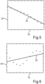
- the speed dynamics i.e. to check whether the dynamics are sufficiently large, the navigation speed values a regression line is determined, and then the mean value of the squared residuals is determined.
- This mean value is also referred to as the MRS value and is, for example, the dynamic value mentioned above. If, for example, the MRS value is below a predefined threshold value, the dynamics are considered to be low. In particular, the dynamics are then considered to be too low to carry out a synchronization attempt to synchronize the speeds. If such a synchronization attempt or the synchronization of the speeds is not carried out, an estimation of the circumference U is not started.
- the synchronization of the speeds is carried out depending on the dynamic value and, for example, when the dynamic value exceeds the threshold value.
- the dynamic value or the exceeding of the threshold value by the dynamic value is a basis or a prerequisite for carrying out the synchronization of the speeds.
- the synchronization of the speed is a basis or prerequisite for determining or estimating the circumference U, so that, in particular indirectly, the dynamic value or the exceeding of the threshold value by the dynamic value is the basis or prerequisite for determining or estimating the circumference value, and thus the circumference U. If the dynamic value and thus the dynamics are sufficiently high, the speeds can then be synchronized and the circumference U can be determined, in particular estimated, with sufficient accuracy.
- This is in Fig. 5 shown.
- Circles illustrate the navigation speed values, and the regression line determined for the navigation speed values is in Fig. 5 is designated as 30.
- the MRS value characterizes, for example, a scatter of the navigation speed values and is, according to Fig. 5 for example 0.06.
- the effects of the temporal latency I and the offset s on the speed difference, i.e. on the difference between the navigation speed and the wheel speed, and the latency or delay I can be determined unambiguously, which, for example, is Fig. 6 is illustrated. Also in Fig. 6 The circles illustrate the navigation speed values. In Fig. 6 The regression line determined for the navigation speed values is also labeled 30 and according to Fig. 6 the MRS value is 1.73.
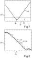
- Fig. 7 shows a diagram on whose abscissa 32 the temporal shift or the temporal difference between the wheel speed and the navigation speed is plotted.
- the ordinate 34 shows the standard deviation.
- the plotted curve 36 in the diagram illustrates the objective function, and a dashed line 38 illustrates a threshold value of the maximum standard deviation.
- the minimum of the objective function is designated m.
- the temporal shift corresponds to the latency sought.
- all navigation speed values are divided by the corresponding wheel speed values. This results in division values from which a mean value and the standard deviation are calculated.
- the objective function represents the course of the calculated standard deviation as a function of the temporal shift.
- the latency calculation is classified as successful if the standard deviation for the shift at which the objective function reaches its minimum value, i.e. its minimum M, is below the threshold value (line 38).
- the mean value of ratios between the navigation and wheel speeds corresponds to a rough estimate of the tire circumference correction factor and is referred to as the scaling factor.
- the wheel speed is corrected with the scaling factor, it approximately corresponds to the synchronized navigation speed, as can be seen from Fig. 8
- the scaled wheel speed is calculated by multiplying the wheel speed shown with the scaling factor, which at least essentially corresponds to the navigation speed.
- the scaled wheel speed is in Fig. 8 marked 22'.
- the navigation speed is also protected. So that the synchronized navigation speed can be used for the safety-relevant calculation, it should be protected. For the protection, a validation is carried out against the wheel speed, which is already protected. Before this, the wheel speed should be corrected with the scaling factor already calculated. As long as the navigation speed is within a tolerance band around the scaled wheel speed, it can also be considered protected. If the navigation speed leaves the tolerance band several times in consecutive update cycles, the protection should be blocked and the estimated latency should be discarded. In this case, the synchronization attempt starts again from the beginning in the next cycle.
- the navigation speed is also referred to as v nav .
- the correction factor also referred to as K HL.
- K HL K HL ⁇ v HL .
- the circumference of the reference wheel at the start of the estimation also known as the tire circumference, is therefore assumed to be equal to the nominal tire circumference.
- the estimation runs throughout the entire journey. However, the estimated correction factor is only used once the filter has converged. The filter convergence is assessed based on the estimated variance of the correction factor (element [0][0] of the covariance matrix).
- a so-called status function maps the variance values on a scale from 0 to 99.
- the smaller the variance the higher the status value and thus the more accurate the estimate.
- S* a predefined threshold value
- Typical signal curves of the correction factor, its variance and the status function are shown in Fig. 12 recognizable.
- Fig. 12 shows diagrams with time plotted on the abscissa 38.
- the correction factor is illustrated by a curve 40, a variance of the correction factor by a curve 42 and the status function by a curve 44.
- the threshold value of the status function is, for example, 80.
- Fig. 13 shows a diagram on whose abscissa 46 the speed is plotted, particularly in the unit of kilometers per hour.
- the correction factor is plotted on the ordinate 48, which is different for different speed ranges GB. It is therefore advantageous to estimate the circumference U or the circumference value separately in different speed ranges.
- Fig. 13 For example, eight different speed ranges GB are used. The respective limits of the speed ranges GB can be chosen almost freely.
- the resulting speed ranges GB do not necessarily have to be equidistant, as in Fig. 13 shown as an example. Preferably, however, the entire speed range should be completely covered.
- a first fallback level designated E1
- E2 contains the mean value of the estimated correction factors of all speed ranges in which the status function has reached the threshold value S*.
- a second fallback level designated E2.1
- a third fallback level designated E2.2
- the fallback levels E2.1 and E2.2 contain a mean value of the estimated correction factors of the speed ranges 1 to 4 and 5 to 8, respectively, in which the status function has reached the threshold value S*.
- the number of speed ranges GB and the number of fallback levels can be increased.
- a number of speed ranges as a power of two is recommended.
- Fig. 10 shows a diagram on whose abscissa 50 the speed is plotted in kilometers per hour. On the ordinate 52 the correction factor is plotted.
- Fig. 10 Results of a high-precision correction factor estimation with a receiver having a refresh rate of 50 Hertz. In this estimation, 64 speed ranges GB were defined. Such estimates can be successfully used for reference determination.
Landscapes
- Engineering & Computer Science (AREA)
- Mechanical Engineering (AREA)
- Transportation (AREA)
- Physics & Mathematics (AREA)
- Automation & Control Theory (AREA)
- Mathematical Physics (AREA)
- Control Of Driving Devices And Active Controlling Of Vehicle (AREA)
- Navigation (AREA)
Claims (8)
- Procédé destiné à déterminer au moins une valeur de la circonférence caractérisant une circonférence (U) d'une roue (10) d'un véhicule, dans lequel :- une vitesse de rotation de la roue (10) est détectée ;- une vitesse de roue (22) de la roue (10) est calculée en tant que première vitesse en fonction de la vitesse de rotation ;- une vitesse de référence (24) du véhicule est déterminée par satellite en tant que seconde vitesse au moyen d'un système de navigation du véhicule ; et- la valeur de la circonférence est déterminée en fonction de la vitesse de roue (22) et de la vitesse de référence (24) ;dans lequel au moins une valeur de dynamique est déterminée, laquelle caractérise une dynamique d'au moins une des vitesses, dans lequel la détermination de la valeur de la circonférence est effectuée en fonction de la valeur de dynamique,caractérisé en ce queplusieurs valeurs de vitesse caractérisant la au moins une vitesse sont déterminées, dans lequel pour les valeurs de vitesse qui caractérisent la au moins une vitesse, une droite de régression (30) est déterminée et, à l'aide des droites de régression, la valeur de dynamique est déterminée en tant que valeur moyenne des résidus quadratiques.
- Procédé selon la revendication 1,
caractérisé en ce que
la détermination de la valeur de la circonférence est effectuée en fonction de la valeur de dynamique lorsque la valeur moyenne est supérieure à une valeur seuil. - Procédé selon l'une quelconque des revendications précédentes,
caractérisé en ce que
les valeurs de vitesse sont enregistrées dans une première mémoire tampon, en particulier dans une première mémoire tampon circulaire. - Procédé selon l'une quelconque des revendications précédentes,
caractérisé en ce que
plusieurs secondes valeurs de vitesse caractérisant l'autre vitesse sont déterminées. - Procédé selon les revendications 3 et 4,
caractérisé en ce que
les secondes valeurs de vitesse qui caractérisent l'autre vitesse sont enregistrées dans une seconde mémoire tampon, en particulier dans une seconde mémoire tampon circulaire. - Procédé selon la revendication 5,
caractérisé en ce que
au moins un déplacement est effectué, lors duquel les premières données de vitesse enregistrées et les secondes données de vitesse enregistrées sont déplacées d'une unité temporelle les unes par rapport aux autres de manière cyclique, dans lequel en fonction du déplacement, au moins une différence entre les vitesses et/ou au moins un rapport des vitesses est déterminé(e), et dans lequel en fonction de la différence déterminée et/ou en fonction du rapport déterminé, la valeur de la circonférence est déterminée. - Procédé selon l'une quelconque des revendications 4 à 6,
caractérisé en ce que
un premier signal (22) comprenant les premières valeurs de vitesse et caractérisant de ce fait la au moins une vitesse et un second signal (24) comprenant les secondes valeurs de vitesse et caractérisant de ce fait l'autre vitesse sont synchronisés. - Véhicule à moteur qui est réalisé pour effectuer un procédé selon l'une quelconque des revendications précédentes.
Applications Claiming Priority (2)
| Application Number | Priority Date | Filing Date | Title |
|---|---|---|---|
| DE102019125655.0A DE102019125655A1 (de) | 2019-09-24 | 2019-09-24 | Verfahren zum Ermitteln eines Umfangs eines Fahrzeugrads sowie Kraftfahrzeug |
| PCT/EP2020/068601 WO2021058155A1 (fr) | 2019-09-24 | 2020-07-02 | Procédé de détermination d'une circonférence de roue de véhicule et véhicule à moteur |
Publications (2)
| Publication Number | Publication Date |
|---|---|
| EP4034443A1 EP4034443A1 (fr) | 2022-08-03 |
| EP4034443B1 true EP4034443B1 (fr) | 2024-10-02 |
Family
ID=71607931
Family Applications (1)
| Application Number | Title | Priority Date | Filing Date |
|---|---|---|---|
| EP20739900.7A Active EP4034443B1 (fr) | 2019-09-24 | 2020-07-02 | Procédé de détermination d'une circonférence de roue de véhicule et véhicule à moteur |
Country Status (3)
| Country | Link |
|---|---|
| EP (1) | EP4034443B1 (fr) |
| DE (1) | DE102019125655A1 (fr) |
| WO (1) | WO2021058155A1 (fr) |
Families Citing this family (5)
| Publication number | Priority date | Publication date | Assignee | Title |
|---|---|---|---|---|
| DE102018222152A1 (de) * | 2018-12-18 | 2020-06-18 | Robert Bosch Gmbh | Verfahren und Vorrichtung zum Ermitteln eines dynamischen Reifenumfangs eines Fortbewegungsmittels |
| DE102021211202A1 (de) | 2021-10-05 | 2023-04-06 | Continental Automotive Technologies GmbH | Reifenumfangsbestimmung mit Kalmanfilter |
| DE102023208663B4 (de) | 2023-09-07 | 2025-03-27 | Volkswagen Aktiengesellschaft | Verfahren zur Bestimmung des Reifenumfangs mindestens eines Fahrzeugrads eines Fahrzeugs |
| CN118876992B (zh) * | 2024-09-29 | 2025-02-11 | 易控智驾科技有限公司 | 无人驾驶车辆实际车速的检测方法、装置和无人驾驶车辆 |
| US20260116393A1 (en) | 2024-10-28 | 2026-04-30 | GM Global Technology Operations LLC | Systems and method configured to limit suspension travel and wheel pivot based on detected wheel diameter |
Family Cites Families (4)
| Publication number | Priority date | Publication date | Assignee | Title |
|---|---|---|---|---|
| DE102006058567A1 (de) * | 2006-12-12 | 2008-06-26 | Siemens Ag | Verfahren und Anordnung zur Ermittlung eines aktualisierten Radumfanges zumindest eines an einem Fahrzeug angeordneten Rades |
| DE102012000213B4 (de) * | 2012-01-07 | 2021-09-23 | Volkswagen Aktiengesellschaft | Verfahren und Vorrichtung zur Bestimmung des Umfangs eines Kraftfahrzeugrades |
| DE102016005470A1 (de) * | 2016-05-03 | 2017-02-09 | Daimler Ag | Verfahren zum Betrieb eines Fahrzeuges |
| DE102017007216A1 (de) * | 2017-07-29 | 2018-03-15 | Daimler Ag | Verfahren zum Schätzen von Achsparametern eines Fahrzeugs |
-
2019
- 2019-09-24 DE DE102019125655.0A patent/DE102019125655A1/de not_active Withdrawn
-
2020
- 2020-07-02 EP EP20739900.7A patent/EP4034443B1/fr active Active
- 2020-07-02 WO PCT/EP2020/068601 patent/WO2021058155A1/fr not_active Ceased
Also Published As
| Publication number | Publication date |
|---|---|
| WO2021058155A1 (fr) | 2021-04-01 |
| DE102019125655A1 (de) | 2021-03-25 |
| EP4034443A1 (fr) | 2022-08-03 |
Similar Documents
| Publication | Publication Date | Title |
|---|---|---|
| EP1692026B1 (fr) | Procede et systeme de surveillance d'un dispositif de mesure dispose dans un vehicule a roues | |
| EP1826530B1 (fr) | Procédé et dispositif destinés à la détection de la dimension d'une roue | |
| EP2755868B1 (fr) | Système capteur comportant une unité de modèle de véhicule | |
| DE102005033237B4 (de) | Verfahren zur Bestimmung und Korrektur von Fehlorientierungen und Offsets der Sensoren einer Inertial Measurement Unit in einem Landfahrzeug | |
| EP1885586B1 (fr) | Determination de l'angle de lacet actuel et de l'angle de derive actuel d'un vehicule routier | |
| DE102019125655A1 (de) | Verfahren zum Ermitteln eines Umfangs eines Fahrzeugrads sowie Kraftfahrzeug | |
| EP2303663B1 (fr) | Dispositif et procédé de détermination de l état de conduite d' un véhicule | |
| WO2019102036A1 (fr) | Procédé, dispositif de commande et système permettant de déterminer une profondeur d'une sculpture d'un pneu | |
| DE102016223902B4 (de) | Verfahren und System zur Bestimmung von Radumfängen und Spurweiten eines Fahrzeugs | |
| DE102016219379A1 (de) | Verfahren zur Ermittlung einer Orientierung eines Fahrzeugs | |
| EP4010234B1 (fr) | Procédé de détermination d'une vitesse locale d'une voiture | |
| WO2013072131A1 (fr) | Procédé permettant de déterminer le rayon de roulement dynamique d'un pneu | |
| EP1826099B1 (fr) | Procédé destiné à la détermination du rapport de direction d'un véhicule | |
| DE102006058567A1 (de) | Verfahren und Anordnung zur Ermittlung eines aktualisierten Radumfanges zumindest eines an einem Fahrzeug angeordneten Rades | |
| DE102006018978A1 (de) | Verfahren zur Bestimmung des Wankwinkels | |
| DE10221900A1 (de) | Verfahren und Vorrichtung zum Bestimmen der Krümmung einer Fahrspur eines Fahrzeugs | |
| DE102018116512A1 (de) | Neue odometrische Berechnungen für eine Eigenbewegung eines Kraftfahrzeugs auf Basis einer Abschätzung von Steifigkeitskoeffizienten | |
| DE10247994B4 (de) | Verfahren und Vorrichtung zur Fahrdynamikregelung | |
| WO2008092730A2 (fr) | Procédé et dispositif pour déterminer un décalage de signal d'un capteur de taux de roulis | |
| EP0979763B1 (fr) | Méthode de détermination du rayon de courbure d'une rue | |
| DE10340053A1 (de) | Bestimmung der Geschwindigkeit über Grund bei fahrdynamischen Anwendungen im Kraftfahrzeug | |
| DE102004055070B4 (de) | Hubkorrektur bei der fahrzeug-basierten Vermessung von Oberflächenprofilen von Fahrbahnen | |
| DE102017010384A1 (de) | Verfahren zur Ermittlung einer Eigenbewegung | |
| DE102004004805A9 (de) | System zum Kompensieren von bei Fahrzeugdynamik-Steuerungen verwendeten Fahrzeugrad-Geschwindigkeiten | |
| DE102017006056A1 (de) | Verfahren zur Ermittlung einer Eigenbewegung eines Fahrzeugs |
Legal Events
| Date | Code | Title | Description |
|---|---|---|---|
| STAA | Information on the status of an ep patent application or granted ep patent |
Free format text: STATUS: UNKNOWN |
|
| STAA | Information on the status of an ep patent application or granted ep patent |
Free format text: STATUS: THE INTERNATIONAL PUBLICATION HAS BEEN MADE |
|
| PUAI | Public reference made under article 153(3) epc to a published international application that has entered the european phase |
Free format text: ORIGINAL CODE: 0009012 |
|
| STAA | Information on the status of an ep patent application or granted ep patent |
Free format text: STATUS: REQUEST FOR EXAMINATION WAS MADE |
|
| 17P | Request for examination filed |
Effective date: 20220425 |
|
| AK | Designated contracting states |
Kind code of ref document: A1 Designated state(s): AL AT BE BG CH CY CZ DE DK EE ES FI FR GB GR HR HU IE IS IT LI LT LU LV MC MK MT NL NO PL PT RO RS SE SI SK SM TR |
|
| DAV | Request for validation of the european patent (deleted) | ||
| DAX | Request for extension of the european patent (deleted) | ||
| P01 | Opt-out of the competence of the unified patent court (upc) registered |
Effective date: 20230529 |
|
| GRAP | Despatch of communication of intention to grant a patent |
Free format text: ORIGINAL CODE: EPIDOSNIGR1 |
|
| STAA | Information on the status of an ep patent application or granted ep patent |
Free format text: STATUS: GRANT OF PATENT IS INTENDED |
|
| GRAS | Grant fee paid |
Free format text: ORIGINAL CODE: EPIDOSNIGR3 |
|
| INTG | Intention to grant announced |
Effective date: 20240730 |
|
| GRAA | (expected) grant |
Free format text: ORIGINAL CODE: 0009210 |
|
| STAA | Information on the status of an ep patent application or granted ep patent |
Free format text: STATUS: THE PATENT HAS BEEN GRANTED |
|
| AK | Designated contracting states |
Kind code of ref document: B1 Designated state(s): AL AT BE BG CH CY CZ DE DK EE ES FI FR GB GR HR HU IE IS IT LI LT LU LV MC MK MT NL NO PL PT RO RS SE SI SK SM TR |
|
| REG | Reference to a national code |
Ref country code: GB Ref legal event code: FG4D Free format text: NOT ENGLISH |
|
| REG | Reference to a national code |
Ref country code: CH Ref legal event code: EP |
|
| REG | Reference to a national code |
Ref country code: DE Ref legal event code: R096 Ref document number: 502020009376 Country of ref document: DE |
|
| REG | Reference to a national code |
Ref country code: IE Ref legal event code: FG4D Free format text: LANGUAGE OF EP DOCUMENT: GERMAN |
|
| REG | Reference to a national code |
Ref country code: LT Ref legal event code: MG9D |
|
| REG | Reference to a national code |
Ref country code: NL Ref legal event code: MP Effective date: 20241002 |
|
| PG25 | Lapsed in a contracting state [announced via postgrant information from national office to epo] |
Ref country code: NL Free format text: LAPSE BECAUSE OF FAILURE TO SUBMIT A TRANSLATION OF THE DESCRIPTION OR TO PAY THE FEE WITHIN THE PRESCRIBED TIME-LIMIT Effective date: 20241002 |
|
| PG25 | Lapsed in a contracting state [announced via postgrant information from national office to epo] |
Ref country code: NL Free format text: LAPSE BECAUSE OF FAILURE TO SUBMIT A TRANSLATION OF THE DESCRIPTION OR TO PAY THE FEE WITHIN THE PRESCRIBED TIME-LIMIT Effective date: 20241002 |
|
| PG25 | Lapsed in a contracting state [announced via postgrant information from national office to epo] |
Ref country code: PT Free format text: LAPSE BECAUSE OF FAILURE TO SUBMIT A TRANSLATION OF THE DESCRIPTION OR TO PAY THE FEE WITHIN THE PRESCRIBED TIME-LIMIT Effective date: 20250203 Ref country code: HR Free format text: LAPSE BECAUSE OF FAILURE TO SUBMIT A TRANSLATION OF THE DESCRIPTION OR TO PAY THE FEE WITHIN THE PRESCRIBED TIME-LIMIT Effective date: 20241002 Ref country code: IS Free format text: LAPSE BECAUSE OF FAILURE TO SUBMIT A TRANSLATION OF THE DESCRIPTION OR TO PAY THE FEE WITHIN THE PRESCRIBED TIME-LIMIT Effective date: 20250202 |
|
| PG25 | Lapsed in a contracting state [announced via postgrant information from national office to epo] |
Ref country code: FI Free format text: LAPSE BECAUSE OF FAILURE TO SUBMIT A TRANSLATION OF THE DESCRIPTION OR TO PAY THE FEE WITHIN THE PRESCRIBED TIME-LIMIT Effective date: 20241002 |
|
| PG25 | Lapsed in a contracting state [announced via postgrant information from national office to epo] |
Ref country code: BG Free format text: LAPSE BECAUSE OF FAILURE TO SUBMIT A TRANSLATION OF THE DESCRIPTION OR TO PAY THE FEE WITHIN THE PRESCRIBED TIME-LIMIT Effective date: 20241002 |
|
| PG25 | Lapsed in a contracting state [announced via postgrant information from national office to epo] |
Ref country code: ES Free format text: LAPSE BECAUSE OF FAILURE TO SUBMIT A TRANSLATION OF THE DESCRIPTION OR TO PAY THE FEE WITHIN THE PRESCRIBED TIME-LIMIT Effective date: 20241002 |
|
| PG25 | Lapsed in a contracting state [announced via postgrant information from national office to epo] |
Ref country code: NO Free format text: LAPSE BECAUSE OF FAILURE TO SUBMIT A TRANSLATION OF THE DESCRIPTION OR TO PAY THE FEE WITHIN THE PRESCRIBED TIME-LIMIT Effective date: 20250102 |
|
| PG25 | Lapsed in a contracting state [announced via postgrant information from national office to epo] |
Ref country code: LV Free format text: LAPSE BECAUSE OF FAILURE TO SUBMIT A TRANSLATION OF THE DESCRIPTION OR TO PAY THE FEE WITHIN THE PRESCRIBED TIME-LIMIT Effective date: 20241002 Ref country code: GR Free format text: LAPSE BECAUSE OF FAILURE TO SUBMIT A TRANSLATION OF THE DESCRIPTION OR TO PAY THE FEE WITHIN THE PRESCRIBED TIME-LIMIT Effective date: 20250103 |
|
| PG25 | Lapsed in a contracting state [announced via postgrant information from national office to epo] |
Ref country code: PL Free format text: LAPSE BECAUSE OF FAILURE TO SUBMIT A TRANSLATION OF THE DESCRIPTION OR TO PAY THE FEE WITHIN THE PRESCRIBED TIME-LIMIT Effective date: 20241002 Ref country code: CZ Free format text: LAPSE BECAUSE OF FAILURE TO SUBMIT A TRANSLATION OF THE DESCRIPTION OR TO PAY THE FEE WITHIN THE PRESCRIBED TIME-LIMIT Effective date: 20241002 |
|
| PG25 | Lapsed in a contracting state [announced via postgrant information from national office to epo] |
Ref country code: RS Free format text: LAPSE BECAUSE OF FAILURE TO SUBMIT A TRANSLATION OF THE DESCRIPTION OR TO PAY THE FEE WITHIN THE PRESCRIBED TIME-LIMIT Effective date: 20250102 |
|
| PG25 | Lapsed in a contracting state [announced via postgrant information from national office to epo] |
Ref country code: SM Free format text: LAPSE BECAUSE OF FAILURE TO SUBMIT A TRANSLATION OF THE DESCRIPTION OR TO PAY THE FEE WITHIN THE PRESCRIBED TIME-LIMIT Effective date: 20241002 |
|
| REG | Reference to a national code |
Ref country code: DE Ref legal event code: R097 Ref document number: 502020009376 Country of ref document: DE |
|
| PG25 | Lapsed in a contracting state [announced via postgrant information from national office to epo] |
Ref country code: DK Free format text: LAPSE BECAUSE OF FAILURE TO SUBMIT A TRANSLATION OF THE DESCRIPTION OR TO PAY THE FEE WITHIN THE PRESCRIBED TIME-LIMIT Effective date: 20241002 |
|
| PG25 | Lapsed in a contracting state [announced via postgrant information from national office to epo] |
Ref country code: EE Free format text: LAPSE BECAUSE OF FAILURE TO SUBMIT A TRANSLATION OF THE DESCRIPTION OR TO PAY THE FEE WITHIN THE PRESCRIBED TIME-LIMIT Effective date: 20241002 |
|
| PG25 | Lapsed in a contracting state [announced via postgrant information from national office to epo] |
Ref country code: RO Free format text: LAPSE BECAUSE OF FAILURE TO SUBMIT A TRANSLATION OF THE DESCRIPTION OR TO PAY THE FEE WITHIN THE PRESCRIBED TIME-LIMIT Effective date: 20241002 |
|
| PG25 | Lapsed in a contracting state [announced via postgrant information from national office to epo] |
Ref country code: SK Free format text: LAPSE BECAUSE OF FAILURE TO SUBMIT A TRANSLATION OF THE DESCRIPTION OR TO PAY THE FEE WITHIN THE PRESCRIBED TIME-LIMIT Effective date: 20241002 |
|
| PG25 | Lapsed in a contracting state [announced via postgrant information from national office to epo] |
Ref country code: IT Free format text: LAPSE BECAUSE OF FAILURE TO SUBMIT A TRANSLATION OF THE DESCRIPTION OR TO PAY THE FEE WITHIN THE PRESCRIBED TIME-LIMIT Effective date: 20241002 |
|
| PLBE | No opposition filed within time limit |
Free format text: ORIGINAL CODE: 0009261 |
|
| STAA | Information on the status of an ep patent application or granted ep patent |
Free format text: STATUS: NO OPPOSITION FILED WITHIN TIME LIMIT |
|
| PG25 | Lapsed in a contracting state [announced via postgrant information from national office to epo] |
Ref country code: SE Free format text: LAPSE BECAUSE OF FAILURE TO SUBMIT A TRANSLATION OF THE DESCRIPTION OR TO PAY THE FEE WITHIN THE PRESCRIBED TIME-LIMIT Effective date: 20241002 |
|
| 26N | No opposition filed |
Effective date: 20250703 |
|
| PGFP | Annual fee paid to national office [announced via postgrant information from national office to epo] |
Ref country code: DE Payment date: 20250731 Year of fee payment: 6 |
|
| PGFP | Annual fee paid to national office [announced via postgrant information from national office to epo] |
Ref country code: GB Payment date: 20250725 Year of fee payment: 6 |
|
| PGFP | Annual fee paid to national office [announced via postgrant information from national office to epo] |
Ref country code: FR Payment date: 20250729 Year of fee payment: 6 |
|
| REG | Reference to a national code |
Ref country code: CH Ref legal event code: H13 Free format text: ST27 STATUS EVENT CODE: U-0-0-H10-H13 (AS PROVIDED BY THE NATIONAL OFFICE) Effective date: 20260224 |
|
| PG25 | Lapsed in a contracting state [announced via postgrant information from national office to epo] |
Ref country code: LU Free format text: LAPSE BECAUSE OF NON-PAYMENT OF DUE FEES Effective date: 20250702 |
|
| REG | Reference to a national code |
Ref country code: BE Ref legal event code: MM Effective date: 20250731 |
|
| PG25 | Lapsed in a contracting state [announced via postgrant information from national office to epo] |
Ref country code: BE Free format text: LAPSE BECAUSE OF NON-PAYMENT OF DUE FEES Effective date: 20250731 |
|
| PG25 | Lapsed in a contracting state [announced via postgrant information from national office to epo] |
Ref country code: CH Free format text: LAPSE BECAUSE OF NON-PAYMENT OF DUE FEES Effective date: 20250731 |
|
| PG25 | Lapsed in a contracting state [announced via postgrant information from national office to epo] |
Ref country code: LT Free format text: LAPSE BECAUSE OF FAILURE TO SUBMIT A TRANSLATION OF THE DESCRIPTION OR TO PAY THE FEE WITHIN THE PRESCRIBED TIME-LIMIT Effective date: 20241002 |
|
| PG25 | Lapsed in a contracting state [announced via postgrant information from national office to epo] |
Ref country code: IE Free format text: LAPSE BECAUSE OF NON-PAYMENT OF DUE FEES Effective date: 20250702 |
|
| PG25 | Lapsed in a contracting state [announced via postgrant information from national office to epo] |
Ref country code: MC Free format text: LAPSE BECAUSE OF FAILURE TO SUBMIT A TRANSLATION OF THE DESCRIPTION OR TO PAY THE FEE WITHIN THE PRESCRIBED TIME-LIMIT Effective date: 20241002 |
|
| PG25 | Lapsed in a contracting state [announced via postgrant information from national office to epo] |
Ref country code: CY Free format text: LAPSE BECAUSE OF FAILURE TO SUBMIT A TRANSLATION OF THE DESCRIPTION OR TO PAY THE FEE WITHIN THE PRESCRIBED TIME-LIMIT Effective date: 20241002 |