EP4034447B1 - Ensemble comprenant une partie de boîtier allongée ayant la forme d'un corps creux et un élément en forme de tige fixé en son sein - Google Patents
Ensemble comprenant une partie de boîtier allongée ayant la forme d'un corps creux et un élément en forme de tige fixé en son sein Download PDFInfo
- Publication number
- EP4034447B1 EP4034447B1 EP20771446.0A EP20771446A EP4034447B1 EP 4034447 B1 EP4034447 B1 EP 4034447B1 EP 20771446 A EP20771446 A EP 20771446A EP 4034447 B1 EP4034447 B1 EP 4034447B1
- Authority
- EP
- European Patent Office
- Prior art keywords
- shaped
- rod
- housing part
- shaped component
- bolt
- Prior art date
- Legal status (The legal status is an assumption and is not a legal conclusion. Google has not performed a legal analysis and makes no representation as to the accuracy of the status listed.)
- Active
Links
Images

Classifications
-
- B—PERFORMING OPERATIONS; TRANSPORTING
- B61—RAILWAYS
- B61G—COUPLINGS; DRAUGHT AND BUFFING APPLIANCES
- B61G9/00—Draw-gear
- B61G9/20—Details; Accessories
- B61G9/24—Linkages between draw-bar and framework
-
- B—PERFORMING OPERATIONS; TRANSPORTING
- B61—RAILWAYS
- B61G—COUPLINGS; DRAUGHT AND BUFFING APPLIANCES
- B61G7/00—Details or accessories
- B61G7/10—Mounting of the couplings on the vehicle
Definitions
- the invention relates to an arrangement with an elongated, hollow body-shaped housing part and a rod-shaped component according to the preamble of claim 1.
- the rod-shaped component is inserted in its longitudinal direction into the housing part and fixed to the housing part, the rod-shaped component and the housing part having openings for the positive reception of a generally bolt-shaped driving device to be inserted in the transverse direction of the rod-shaped component.
- two components here the elongated, hollow body-shaped housing part and the rod-shaped component, have to be coupled with easily detachable connections in order to transmit forces acting in the longitudinal direction of the rod-shaped component.
- positive power transmissions are generally preferred.
- the elongated, hollow body-shaped housing part can be at least a section of a base frame of the rail vehicle and the rod-shaped component can be a coupling rod.
- transverse wedges For the positive connection of an elongated, hollow body-shaped housing part and a rod-shaped component, it is also known to use transverse wedges. In contrast to a cylindrical bolt made of solid material, such transverse wedges are insensitive to dimensional and storage deviations of the components, as they can create a preload over a certain working range.
- the disadvantage of using transverse wedges is that each transverse wedge only transmits forces in one direction and is therefore only effective against a fixed stop or in a double arrangement.
- tolerance against dimensional deviations or plasticization when driving in the transverse wedges in conjunction with flat wedge angles requires correspondingly long nominal projections of the transverse wedges on both sides of the elongated, hollow body-shaped housing part.
- the invention is based on the object of further developing an arrangement of the type mentioned in such a way that the rod-shaped component is fixed with as little play as possible within the elongated, hollow body-shaped Housing part is realized, taking into account dimensional tolerances of the components involved.
- a load is transferred from the rod-shaped component via one of the beams in each load direction in a form-fitting manner to the elongated, hollow body-shaped housing part.
- the bars of the bolt-shaped driving device running in the transverse direction of the rod-shaped component and the elongated, hollow-body-shaped component are preferably interlocked.
- This arrangement enables a single, continuous opening in both the elongated, hollow-body-shaped housing part and in the rod-shaped component, which is each loaded outwards, while in a non-interlaced arrangement the beams are either in the elongated, hollow-body-shaped housing part or in the rod-shaped component
- An intermediate bridge would have to be provided, which would be loaded on both sides. This would require a multiple length of the arrangement.
- a pressure piece of the first beam provided for contact with contact surfaces of the rod-shaped component forms a main body of the first beam and end-side cylindrical functional surface sections of the first beam the housing part a first load path for transmitting longitudinal forces acting on the rod-shaped component in a first direction and a pressure piece of the second beam provided for contact with contact surfaces of the rod-shaped component, a main body of the second beam and end-side cylindrical functional surface sections of the second beam to the housing part a second Load path for transmitting longitudinal forces acting on the rod-shaped component in a second direction opposite the first direction, the wedge-shaped contact surfaces of the beams adjoining the housing part on the end-side, cylindrical functional surface sections in the insertion direction of the bolt-shaped driving device.
- the bolt-shaped driving device can have a drive at one of its ends for moving the beams in the transverse direction of the rod-shaped component.
- the drive can in particular be designed as a cover that can be screwed against the housing part. Screwing the cover into the associated opening of the housing part then causes the bolt-shaped driving device to move in the transverse direction of the rod-shaped component until the bolt-shaped driving device reaches its tensioned operating position while engaging in the openings of the housing part.
- the wedge-shaped contact surfaces of the housing part can be limited in their area of action by a transition to the functional surface sections running in the transverse direction of the rod-shaped component in such a way that in a final phase of a transverse movement of the bolt-shaped Driving device in its operating position no longer changes relative position of the bar.
- each beam is connected to its pressure piece via an elastic element.
- the elastic elements are designed as rubber layers inserted or vulcanized between the respective beams and the pressure pieces assigned to them.
- the pressure pieces are made in one piece with the associated beams.
- the end contact surfaces of the bars can be provided for direct contact with the material of the housing part, so that in this case the bars engage directly in the intended opening edge sections of the housing part.
- the end contact surfaces of the beams can rest on an intermediate piece which is inserted into one of the opening edge sections of the housing part.
- Such an intermediate piece can in particular be designed as a socket with a cylindrical fit in the opening of the housing part.
- the bolt-shaped driving device to engage at one end directly into an opening edge section of the housing part, for example at its drive end, and to engage at its other end in a socket which is inserted into the associated opening edge section of the housing part.
- a socket in only one of the opening edge sections of the elongated hollow body-shaped housing part
- wedge-shaped contact surfaces that engage directly on the housing part can be designed in such a way that the cylindrical area is already reached at the end before the wedge-shaped contact surfaces come into engagement with the socket.
- prestressing forces and the contact surfaces between the pressure pieces of the beams and the rod-shaped component can be designed in such a way that the bolt-shaped driving device can be displaced in a plane perpendicular to the longitudinal direction of the rod-shaped component, i.e. H. Transverse mobility of the rod-shaped component in the housing is made possible after assembly.
- the rod-shaped component is preferably designed as a coupling rod and the housing part as part of a base frame of the rail vehicle.
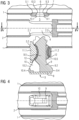
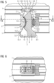
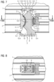
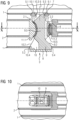
- Figure 1 shows an arrangement with an elongated, hollow body-shaped housing part 1 and a rod-shaped component 2, which is inserted into the housing part 1 in its longitudinal direction.
- the elongated, hollow body-shaped housing part 1 would be identified with a base frame and the rod-shaped component 2 with a coupling rod of such a vehicle.
- the Rod-shaped component 2 is fixed in its operating position in the housing part 1 with the aid of a bolt-shaped driving device 3 which is cylindrical in cross section at its two outer ends.
- the rod-shaped component 2 has a through opening 4, which is assigned to a central part of the bolt-shaped driving device 3.
- the elongated, hollow body-shaped housing part 1 has a continuous opening 5 with opening edge sections 5.1, 5.2.
- opening edge sections 5.1, 5.2 are designed in their position and extent such that the bolt-shaped driving device 3 can be inserted into the openings 4, 5 along an axis 6 in the transverse direction of the rod-shaped component 2, namely while exercising a Prestressing in the longitudinal direction of the rod-shaped component 2.
- a bushing 7 is inserted into the opening edge section 5.1, so that the bolt-shaped driving device 3 does not interact directly with the material of the housing part 1, but via the bushing 7.
- the bolt-shaped driving device 3 has two interlocked beams 9, 10 aligned in the transverse direction of the rod-shaped component 2. Each of these beams 9, 10 is associated with a pressure piece 11, which is connected to a main body of the respective beam 9, 10 via an elastic rubber layer 12, for example by vulcanization.
- the pressure pieces 11 rest directly on assigned contact surfaces of the rod-shaped component 2 to form a positive connection.
- the rubber layers 12 enable any dimensional tolerances of the components involved to be compensated for.
- Both ends of the beams 9, 10 each show wedge-shaped contact surfaces 9.1, 9.2 or 10.1, 10.2 for interaction with the elongated, hollow body-shaped housing part 1.
- the wedge-shaped contact surfaces 9.1, 10.1 lie on the side of the bolt-shaped driving device 3 opposite the cover 8 Inside of socket 7.
- functional surface sections 9.3, 10.3 of the beams 9, 10 adjacent to the wedge-shaped contact surfaces 9.1, 10.1 of the socket 7 are, in contrast, cylindrical.
- the functional surface sections 9.4, 10. 4 of the beams 9, 10 adjoining the cover 8 are also cylindrical and lie against an inside of the opening edge section 5.2 in the operating position of the bolt-shaped driving device 3.
- the wedge-shaped contact surfaces 9.2 and 10.2 adjoin these cylindrical functional surface sections 9.4, 10.4 in the direction of the opening edge section 5.1.
Landscapes
- Engineering & Computer Science (AREA)
- Mechanical Engineering (AREA)
- Mutual Connection Of Rods And Tubes (AREA)
- Clamps And Clips (AREA)
Claims (12)
- Dispositif comprenant une partie (1) de boîtier oblongue en forme de corps creux et une pièce (2) en forme de barre, qui est engagée dans sa direction longitudinale dans la partie (1) du boîtier et qui est immobilisée sur la partie (1) du boîtier, dans lequel la pièce (2) en forme de barre et la partie (1) de boîtier ont des ouvertures (4, 5) de réception à complémentarité de forme d'un système (3) d'entraîneur à insérer dans la direction transversale de la pièce (2) en forme de barre et d'une manière générale en forme d'axe,
caractérisé en ce que
le système (3) d'entraîneur d'une manière générale en forme d'axe est subdivisé dans sa direction transversale en deux poutrelles (9, 10), dans lequel les surfaces (9.1, 9.2, 10.1, 10.2) de contact des poutrelles (9, 10) avec la partie (1) du boîtier sont constituées en forme de coins, de manière à ce qu'une insertion du système (3) d'entraîneur en forme d'axe dans la direction transversale de la pièce (2) en forme de barre provoque une précontrainte du système (3) d'entraîneur en forme d'axe dans la direction longitudinale de la pièce (2) en forme de barre. - Dispositif suivant la revendication 1,
caractérisé en ce que
les poutrelles (9, 10) du système (3) d'entraîneur en forme d'axe s'entrelacent. - Dispositif suivant la revendication 1 ou 2,
caractérisé en ce qu'une pièce (11.1) de pression, prévue pour s'appliquer à des surfaces (2.1) de contact de la pièce (2) en forme de barre, de la première poutrelle (9)un corps (9.5) principal de la première poutrelle (9) et des parties (9.3, 9.4) de surface fonctionnelle cylindriques du côté de l'extrémité de la première poutrelle (9) forment, par rapport à la partie (1) du boîtier,un premier chemin de charge, pour la transmission dans un premier sens de forces longitudinales s'appliquant à la pièce (2) en forme de barre, ainsi qu'une pièce (11.2) de pression, prévue pour s'appliquer à des surfaces (2.2) de contact de la pièce (2) en forme de barre, de la deuxième poutrelle (10),un corps (10.5) principal de la deuxième poutrelle (10) et des parties (10.3, 10.4) de surface fonctionnelle cylindriques, du côté de l'extrémité de la deuxième poutrelle (10), forment, par rapport à la partie (1) de boîtier, un deuxième chemin de charge pour la transmission de forces longitudinales dans un deuxième sens contraire au premier sens s'appliquant à la pièce (2) en forme de barre, dans lequel les surfaces (9.1, 9.2, 10.1, 10.2) de contact en forme de coins des poutrelles (9, 10) voisines, par rapport à la partie (1) du boîtier sont voisines des parties (9.3, 9.4, 10.3, 10.4) de surface fonctionnelle cylindriques du côté de l'extrémité dans la direction d'insertion du système (3) d'entraîneur en forme d'axe. - Dispositif suivant l'une des revendications 1 à 3,
caractérisé en ce que
le système (3) d'entraîneur en forme d'axe a, à l'une de ses extrémités, un entraînement pour le déplacement des poutrelles (9, 10) dans la direction transversale de la pièce (2) en forme de barre. - Dispositif suivant la revendication 4,
caractérisé en ce que
l'entraînement est réalisé en couvercle (8) pouvant se visser sur la partie du boîtier. - Dispositif suivant l'une des revendications 1 à 5,
caractérisé en ce que
les surfaces (9.1, 10.1) de contact en forme de coins de la partie du boîtier sont délimitées dans leur domaine d'action sur les parties (9.3, 10.3) de surface fonctionnelle s'étendant dans la direction transversale de la pièce (2) en forme d'axe, de manière à ce qu'il ne se produise plus de modification relative de position de ses poutrelles (9, 10) dans sa position de fonctionnement dans une dernière phase d'un mouvement transversal du système (3) d'entraîneur en forme d'axe. - Dispositif suivant l'une des revendications 1 à 6,
caractérisé en ce que
pour chaque poutrelle (9, 10) son corps (9.5, 10.5) principal est relié à sa pièce (11.1, 11.2) de pression par un élément (12) élastique. - Dispositif suivant l'une des revendications 1 à 7,
caractérisé en ce que
les parties (9.4, 10.4) de surface fonctionnelle du côté de l'extrémité des poutrelles (9, 10) sont prévues pour s'appliquer directement à du matériau de la partie (1) du boîtier. - Dispositif suivant l'une des revendications 1 à 8,
caractérisé en ce que
les parties (9.3, 10.3) de surface fonctionnelle du côté de l'extrémité des poutrelles (9, 10) sont prévues pour s'appliquer à une pièce intermédiaire, qui est insérée dans l'une des parties (5) de bord d'ouverture de la partie (1) du boîtier. - Dispositif suivant la revendication 9,
caractérisé en ce que
la pièce intermédiaire est constituée sous la forme d'une douille (7) à ajustement cylindrique dans la partie (1) du boîtier. - Dispositif suivant l'une des revendications 1 à 10,
caractérisé en ce que
des forces de précontraintes et les surfaces de contact sont appliquées entre les pièces (11.1, 11.2) de pression des poutrelles (9, 10) et la pièce (2) en forme de barre, de manière à rendre possible un déplacement du système (3) d'entraîneur en forme d'axe dans un plan perpendiculaire à la direction longitudinale de la pièce (2) en forme de barre. - Dispositif suivant l'une des revendications 1 à 11,
caractérisé en ce que
la pièce (2) en forme de barre est constituée sous la forme d'une barre d'accouplement d'un véhicule ferroviaire et la partie (1) de boîtier sous la forme d'une partie d'un châssis d'un véhicule ferroviaire.
Applications Claiming Priority (2)
| Application Number | Priority Date | Filing Date | Title |
|---|---|---|---|
| DE102019214569 | 2019-09-24 | ||
| PCT/EP2020/073671 WO2021058215A1 (fr) | 2019-09-24 | 2020-08-25 | Ensemble comprenant une partie de boîtier allongée ayant la forme d'un corps creux et un élément en forme de tige fixé en son sein |
Publications (3)
| Publication Number | Publication Date |
|---|---|
| EP4034447A1 EP4034447A1 (fr) | 2022-08-03 |
| EP4034447C0 EP4034447C0 (fr) | 2023-10-18 |
| EP4034447B1 true EP4034447B1 (fr) | 2023-10-18 |
Family
ID=72473494
Family Applications (1)
| Application Number | Title | Priority Date | Filing Date |
|---|---|---|---|
| EP20771446.0A Active EP4034447B1 (fr) | 2019-09-24 | 2020-08-25 | Ensemble comprenant une partie de boîtier allongée ayant la forme d'un corps creux et un élément en forme de tige fixé en son sein |
Country Status (3)
| Country | Link |
|---|---|
| EP (1) | EP4034447B1 (fr) |
| ES (1) | ES2968969T3 (fr) |
| WO (1) | WO2021058215A1 (fr) |
Family Cites Families (4)
| Publication number | Priority date | Publication date | Assignee | Title |
|---|---|---|---|---|
| AT290617B (de) * | 1967-01-12 | 1971-06-11 | Stabeg Appbau Gmbh | Lagerung einer selbsttätigen Mittel-Zugkupplung für Schienenfahrzeuge |
| CA2094838C (fr) * | 1992-07-14 | 1999-03-16 | Richard W. Dawson | Timon d'attelage |
| US5360124A (en) * | 1993-07-27 | 1994-11-01 | Mcconway & Torley Corporation | Slackless buff gear connection system with sliding yoke casting |
| CA2156657C (fr) * | 1994-11-02 | 1999-06-15 | Richard G. Beauclerc | Clavette a gravite pour dispositif d'attelage sans jeu de wagon de chemin de fer |
-
2020
- 2020-08-25 WO PCT/EP2020/073671 patent/WO2021058215A1/fr not_active Ceased
- 2020-08-25 EP EP20771446.0A patent/EP4034447B1/fr active Active
- 2020-08-25 ES ES20771446T patent/ES2968969T3/es active Active
Also Published As
| Publication number | Publication date |
|---|---|
| ES2968969T3 (es) | 2024-05-14 |
| EP4034447C0 (fr) | 2023-10-18 |
| EP4034447A1 (fr) | 2022-08-03 |
| WO2021058215A1 (fr) | 2021-04-01 |
Similar Documents
| Publication | Publication Date | Title |
|---|---|---|
| EP4191080A1 (fr) | Moyen de raccordement | |
| DE60108561T2 (de) | Wälzlagergleitführung | |
| DE102016110578B3 (de) | Strukturbauteil für ein Kraftfahrzeug mit Verstärkungselement | |
| EP2592965B1 (fr) | Tiroir avec deux panneaux latéraux et unpanneu arrière | |
| EP3087337B1 (fr) | Échangeur de chaleur à joint périphérique | |
| EP4034447B1 (fr) | Ensemble comprenant une partie de boîtier allongée ayant la forme d'un corps creux et un élément en forme de tige fixé en son sein | |
| EP1950470B1 (fr) | Dispositif de tiges de changement de vitesses | |
| EP1548196A1 (fr) | Elément de connection pour une liaison à haute résistance à la flexion entre éléments de construction | |
| EP3111108B1 (fr) | Maillon bloqué à rainure de dégagement | |
| EP0717204A1 (fr) | Goujon de sécurité, qui peut être inséré dans des trous passant dans des pièces jusqu'à une butée | |
| DE3248072A1 (de) | Durch kaltverformung an ihren laengs- oder querraendern mit nachbarplatten verbindbare platte | |
| DE102020111133A1 (de) | Profilstrebe, insbesondere für ein Kraftfahrzeug | |
| EP0745732A1 (fr) | Elément pour dalle en console empêchant un pont thermique | |
| AT506594B1 (de) | Verbindungselement | |
| EP4112415B1 (fr) | Dispositif d'accouplement pourvu de collier de serrage | |
| EP4112416B1 (fr) | Dispositif d'accouplement pourvu de blocs-ressorts monobloc | |
| EP0135716B1 (fr) | Dispositif de liaison entre les parties séparées d'un pieu batter armé | |
| DE10013144B4 (de) | Knebelverbindung | |
| EP0779408B1 (fr) | Fixation d'un montant d'échelle à une paumelle d'articulation pour échelle | |
| CH721046B1 (de) | Verbindungsvorrichtung zum Verbinden von Rinnenelementen und Entwässerungssystem | |
| DE10341323B4 (de) | Verbindung der Stirnseiten von zwei Hohlprofilen oder geschweißten Kastenprofilträgern (Verbindung 3-schnittig) | |
| DE102023201010A1 (de) | Kontaktierungsanordnung zum miteinander Koppeln einer elektrischen Maschine und einer Leistungselektronik, System für ein Fahrzeug und Fahrzeug | |
| EP4477933A1 (fr) | Système d'étanchéité pour segments de tuyau et procédé de fabrication d'un système d'étanchéité | |
| DE202013009743U1 (de) | Schienenverbindung | |
| DE102020111134A1 (de) | Profilstrebe, insbesondere für ein Kraftfahrzeug |
Legal Events
| Date | Code | Title | Description |
|---|---|---|---|
| STAA | Information on the status of an ep patent application or granted ep patent |
Free format text: STATUS: UNKNOWN |
|
| STAA | Information on the status of an ep patent application or granted ep patent |
Free format text: STATUS: THE INTERNATIONAL PUBLICATION HAS BEEN MADE |
|
| PUAI | Public reference made under article 153(3) epc to a published international application that has entered the european phase |
Free format text: ORIGINAL CODE: 0009012 |
|
| STAA | Information on the status of an ep patent application or granted ep patent |
Free format text: STATUS: REQUEST FOR EXAMINATION WAS MADE |
|
| 17P | Request for examination filed |
Effective date: 20220225 |
|
| AK | Designated contracting states |
Kind code of ref document: A1 Designated state(s): AL AT BE BG CH CY CZ DE DK EE ES FI FR GB GR HR HU IE IS IT LI LT LU LV MC MK MT NL NO PL PT RO RS SE SI SK SM TR |
|
| DAV | Request for validation of the european patent (deleted) | ||
| DAX | Request for extension of the european patent (deleted) | ||
| GRAP | Despatch of communication of intention to grant a patent |
Free format text: ORIGINAL CODE: EPIDOSNIGR1 |
|
| STAA | Information on the status of an ep patent application or granted ep patent |
Free format text: STATUS: GRANT OF PATENT IS INTENDED |
|
| INTG | Intention to grant announced |
Effective date: 20230510 |
|
| GRAS | Grant fee paid |
Free format text: ORIGINAL CODE: EPIDOSNIGR3 |
|
| GRAA | (expected) grant |
Free format text: ORIGINAL CODE: 0009210 |
|
| STAA | Information on the status of an ep patent application or granted ep patent |
Free format text: STATUS: THE PATENT HAS BEEN GRANTED |
|
| AK | Designated contracting states |
Kind code of ref document: B1 Designated state(s): AL AT BE BG CH CY CZ DE DK EE ES FI FR GB GR HR HU IE IS IT LI LT LU LV MC MK MT NL NO PL PT RO RS SE SI SK SM TR |
|
| REG | Reference to a national code |
Ref country code: GB Ref legal event code: FG4D Free format text: NOT ENGLISH |
|
| REG | Reference to a national code |
Ref country code: CH Ref legal event code: EP |
|
| REG | Reference to a national code |
Ref country code: IE Ref legal event code: FG4D Free format text: LANGUAGE OF EP DOCUMENT: GERMAN |
|
| REG | Reference to a national code |
Ref country code: DE Ref legal event code: R096 Ref document number: 502020005712 Country of ref document: DE |
|
| U01 | Request for unitary effect filed |
Effective date: 20231110 |
|
| U07 | Unitary effect registered |
Designated state(s): AT BE BG DE DK EE FI FR IT LT LU LV MT NL PT SE SI Effective date: 20231116 |
|
| PG25 | Lapsed in a contracting state [announced via postgrant information from national office to epo] |
Ref country code: GR Free format text: LAPSE BECAUSE OF FAILURE TO SUBMIT A TRANSLATION OF THE DESCRIPTION OR TO PAY THE FEE WITHIN THE PRESCRIBED TIME-LIMIT Effective date: 20240119 |
|
| PG25 | Lapsed in a contracting state [announced via postgrant information from national office to epo] |
Ref country code: IS Free format text: LAPSE BECAUSE OF FAILURE TO SUBMIT A TRANSLATION OF THE DESCRIPTION OR TO PAY THE FEE WITHIN THE PRESCRIBED TIME-LIMIT Effective date: 20240218 |
|
| PG25 | Lapsed in a contracting state [announced via postgrant information from national office to epo] |
Ref country code: IS Free format text: LAPSE BECAUSE OF FAILURE TO SUBMIT A TRANSLATION OF THE DESCRIPTION OR TO PAY THE FEE WITHIN THE PRESCRIBED TIME-LIMIT Effective date: 20240218 Ref country code: GR Free format text: LAPSE BECAUSE OF FAILURE TO SUBMIT A TRANSLATION OF THE DESCRIPTION OR TO PAY THE FEE WITHIN THE PRESCRIBED TIME-LIMIT Effective date: 20240119 |
|
| REG | Reference to a national code |
Ref country code: ES Ref legal event code: FG2A Ref document number: 2968969 Country of ref document: ES Kind code of ref document: T3 Effective date: 20240514 |
|
| PG25 | Lapsed in a contracting state [announced via postgrant information from national office to epo] |
Ref country code: RS Free format text: LAPSE BECAUSE OF FAILURE TO SUBMIT A TRANSLATION OF THE DESCRIPTION OR TO PAY THE FEE WITHIN THE PRESCRIBED TIME-LIMIT Effective date: 20231018 Ref country code: PL Free format text: LAPSE BECAUSE OF FAILURE TO SUBMIT A TRANSLATION OF THE DESCRIPTION OR TO PAY THE FEE WITHIN THE PRESCRIBED TIME-LIMIT Effective date: 20231018 Ref country code: NO Free format text: LAPSE BECAUSE OF FAILURE TO SUBMIT A TRANSLATION OF THE DESCRIPTION OR TO PAY THE FEE WITHIN THE PRESCRIBED TIME-LIMIT Effective date: 20240118 Ref country code: HR Free format text: LAPSE BECAUSE OF FAILURE TO SUBMIT A TRANSLATION OF THE DESCRIPTION OR TO PAY THE FEE WITHIN THE PRESCRIBED TIME-LIMIT Effective date: 20231018 |
|
| REG | Reference to a national code |
Ref country code: DE Ref legal event code: R097 Ref document number: 502020005712 Country of ref document: DE |
|
| PG25 | Lapsed in a contracting state [announced via postgrant information from national office to epo] |
Ref country code: CZ Free format text: LAPSE BECAUSE OF FAILURE TO SUBMIT A TRANSLATION OF THE DESCRIPTION OR TO PAY THE FEE WITHIN THE PRESCRIBED TIME-LIMIT Effective date: 20231018 |
|
| PG25 | Lapsed in a contracting state [announced via postgrant information from national office to epo] |
Ref country code: SK Free format text: LAPSE BECAUSE OF FAILURE TO SUBMIT A TRANSLATION OF THE DESCRIPTION OR TO PAY THE FEE WITHIN THE PRESCRIBED TIME-LIMIT Effective date: 20231018 |
|
| PG25 | Lapsed in a contracting state [announced via postgrant information from national office to epo] |
Ref country code: SM Free format text: LAPSE BECAUSE OF FAILURE TO SUBMIT A TRANSLATION OF THE DESCRIPTION OR TO PAY THE FEE WITHIN THE PRESCRIBED TIME-LIMIT Effective date: 20231018 Ref country code: SK Free format text: LAPSE BECAUSE OF FAILURE TO SUBMIT A TRANSLATION OF THE DESCRIPTION OR TO PAY THE FEE WITHIN THE PRESCRIBED TIME-LIMIT Effective date: 20231018 Ref country code: RO Free format text: LAPSE BECAUSE OF FAILURE TO SUBMIT A TRANSLATION OF THE DESCRIPTION OR TO PAY THE FEE WITHIN THE PRESCRIBED TIME-LIMIT Effective date: 20231018 Ref country code: CZ Free format text: LAPSE BECAUSE OF FAILURE TO SUBMIT A TRANSLATION OF THE DESCRIPTION OR TO PAY THE FEE WITHIN THE PRESCRIBED TIME-LIMIT Effective date: 20231018 |
|
| PLBE | No opposition filed within time limit |
Free format text: ORIGINAL CODE: 0009261 |
|
| STAA | Information on the status of an ep patent application or granted ep patent |
Free format text: STATUS: NO OPPOSITION FILED WITHIN TIME LIMIT |
|
| 26N | No opposition filed |
Effective date: 20240719 |
|
| U20 | Renewal fee for the european patent with unitary effect paid |
Year of fee payment: 5 Effective date: 20240819 |
|
| REG | Reference to a national code |
Ref country code: CH Ref legal event code: PL |
|
| PG25 | Lapsed in a contracting state [announced via postgrant information from national office to epo] |
Ref country code: MC Free format text: LAPSE BECAUSE OF FAILURE TO SUBMIT A TRANSLATION OF THE DESCRIPTION OR TO PAY THE FEE WITHIN THE PRESCRIBED TIME-LIMIT Effective date: 20231018 Ref country code: CH Free format text: LAPSE BECAUSE OF NON-PAYMENT OF DUE FEES Effective date: 20240831 |
|
| PG25 | Lapsed in a contracting state [announced via postgrant information from national office to epo] |
Ref country code: IE Free format text: LAPSE BECAUSE OF NON-PAYMENT OF DUE FEES Effective date: 20240825 |
|
| U20 | Renewal fee for the european patent with unitary effect paid |
Year of fee payment: 6 Effective date: 20250820 |
|
| PGFP | Annual fee paid to national office [announced via postgrant information from national office to epo] |
Ref country code: GB Payment date: 20250902 Year of fee payment: 6 |
|
| U1H | Name or address of the proprietor changed after the registration of the unitary effect |
Owner name: SIEMENS MOBILITY GMBH; DE |
|
| PG25 | Lapsed in a contracting state [announced via postgrant information from national office to epo] |
Ref country code: CY Free format text: LAPSE BECAUSE OF FAILURE TO SUBMIT A TRANSLATION OF THE DESCRIPTION OR TO PAY THE FEE WITHIN THE PRESCRIBED TIME-LIMIT; INVALID AB INITIO Effective date: 20200825 |
|
| PGFP | Annual fee paid to national office [announced via postgrant information from national office to epo] |
Ref country code: ES Payment date: 20251124 Year of fee payment: 6 |
|
| PG25 | Lapsed in a contracting state [announced via postgrant information from national office to epo] |
Ref country code: HU Free format text: LAPSE BECAUSE OF FAILURE TO SUBMIT A TRANSLATION OF THE DESCRIPTION OR TO PAY THE FEE WITHIN THE PRESCRIBED TIME-LIMIT; INVALID AB INITIO Effective date: 20200825 |