EP4034793B1 - Raccord de tuyau - Google Patents
Raccord de tuyau Download PDFInfo
- Publication number
- EP4034793B1 EP4034793B1 EP20838985.8A EP20838985A EP4034793B1 EP 4034793 B1 EP4034793 B1 EP 4034793B1 EP 20838985 A EP20838985 A EP 20838985A EP 4034793 B1 EP4034793 B1 EP 4034793B1
- Authority
- EP
- European Patent Office
- Prior art keywords
- coupling
- hose
- retaining
- head
- coupling element
- Prior art date
- Legal status (The legal status is an assumption and is not a legal conclusion. Google has not performed a legal analysis and makes no representation as to the accuracy of the status listed.)
- Active
Links
Images


Classifications
-
- F—MECHANICAL ENGINEERING; LIGHTING; HEATING; WEAPONS; BLASTING
- F16—ENGINEERING ELEMENTS AND UNITS; GENERAL MEASURES FOR PRODUCING AND MAINTAINING EFFECTIVE FUNCTIONING OF MACHINES OR INSTALLATIONS; THERMAL INSULATION IN GENERAL
- F16L—PIPES; JOINTS OR FITTINGS FOR PIPES; SUPPORTS FOR PIPES, CABLES OR PROTECTIVE TUBING; MEANS FOR THERMAL INSULATION IN GENERAL
- F16L27/00—Adjustable joints; Joints allowing movement
- F16L27/02—Universal joints, i.e. with mechanical connection allowing angular movement or adjustment of the axes of the parts in any direction
- F16L27/04—Universal joints, i.e. with mechanical connection allowing angular movement or adjustment of the axes of the parts in any direction with partly-spherical engaging surfaces
Definitions
- the invention relates to a hose coupling with a coupling element that is provided on a hose end of a flexible hose line, and with a coupling counter-element that can be releasably connected to the coupling element, with at least one fluid channel being guided in the coupling element and in the coupling counter-element, and wherein the fluid channels of the coupling element and of the counter-coupling element connected thereto are connected to one another in a liquid-tight manner in a holding position of the coupling element and counter-coupling element.
- hose lines are connected, for example, to the sanitary outlet fitting and/or the inlet-side water connection via a hose coupling of the type mentioned at the outset.
- the previously known hose couplings have a coupling element which can be releasably connected to a coupling counter-element via a screw connection.
- EP 3 112 737 A1 discloses a coupling assembly with coupling bodies and coupling clamp for pipes, one of the coupling bodies being insertable with a body part into a body part of the other coupling body with its front end through a front end of the female coupling body.
- a drainage device on flush-mounted cisterns is known, with a drain angle piece being arranged in a vertically displaceable manner in a cover box which is also laid under plaster below the cistern, with a seal being provided which, in all displacement positions, holds the vertical leg of the angle piece on a drain connection piece coming from the cistern seals, and further wherein the cover box has a vertically extending opening to allow displacement of the downstream end of the drain elbow.
- the solution to this problem according to the invention consists, in particular, in that the coupling element or the coupling counter-element has a coupling head which, in a pivoted position, can be inserted into a coupling head receptacle of the respective other element of the hose coupling, and that the coupling element and the coupling counter-element can be pivoted relative to one another between the pivoting position and the holding position, in which holding position the coupling head is held in the coupling head receptacle.
- the hose coupling according to the invention has a coupling element which is provided on a hose end of a flexible hose line.
- a coupling counter-element of the hose coupling can be releasably connected to this coupling element.
- At least one fluid channel is guided in the clutch element and in the clutch counter-element, with the fluid channels located in the clutch element or in the clutch counter-element being connected to one another in a liquid-tight manner when the clutch element and clutch counter-element are in a holding position.
- the coupling element or the coupling counter-element of the hose coupling according to the invention has a coupling head which, in a pivoted position, can be inserted into a coupling head receptacle of the respective other element of the hose coupling.
- the coupling element and the coupling counter-element can be pivoted relative to one another between the pivoted position and the holding position, in which holding position the coupling head is held in the coupling head receptacle. Since the coupling element with the hose coupling according to the invention the coupling counter-element can only be connected to one another by a pivoting movement into the holding position, and since a screw connection is not required to connect the coupling element and the coupling counter-element, the hose coupling according to the invention is characterized by the simple, quick and secure connection of its coupling element and its coupling -counter element off.
- the coupling head is designed as a ball head and the coupling head receptacle is designed as a preferably spherical joint socket.
- the liquid-tight connection of the hose coupling according to the invention in the area of its coupling element, or the coupling counter-element, is additionally promoted if the coupling head or the coupling head receptacle has at least one circumferential seal that is in sealing contact with the other element of the hose coupling.
- a circumferential groove can be provided in the coupling head receptacle, in which a sealing ring rests, which sealing ring bears sealingly on the coupling head of the hose coupling.
- a particularly advantageous embodiment in which a high degree of tightness is ensured in all pivoting positions of the coupling element and coupling counter-element, provides that the coupling head has a circumferential Seal wears which seal in the Holding position on a wall delimiting the coupling head receptacle is tight.
- a structurally simple and particularly advantageous embodiment according to the invention provides that the coupling element is designed in the form of a sleeve, and that the partial area of the coupling element facing the flexible hose line is designed as a connecting piece, onto which connecting piece the associated hose end of the hose line can be pushed.
- the connecting piece has a holding profile on its outer circumference. So that the elastic material of the flexible hose line can dig into the retaining profile in the area of the hose end, it is advantageous if the hose end pushed onto the connecting piece is surrounded by a pressed crimp or pinch sleeve. The hose end of the flexible hose line is held firmly and securely on the connecting piece of the coupling element by means of this pressed crimp or squeezing sleeve.
- the coupling element has an annular flange or annular shoulder on the outer circumference, which serves as a sliding stop when the associated hose end of the hose line is pushed on.
- a particularly simple and expedient embodiment according to the invention provides that the coupling element carries the ball head on its sleeve end region facing away from the connecting piece.
- a preferred development according to the invention provides that in the sleeve portion of the coupling element protruding beyond the hose end of the hose line, a retaining flange protrudes on the outer circumference, which in the retaining position at least partially engages behind a retaining wall, which retaining wall in the direction of insertion is arranged in front of the coupling receptacle. Since in this further developing embodiment the coupling element inserted into the coupling counter-element engages behind the retaining wall with its retaining flange projecting on the outer circumference, the coupling element is secured against unintentional axial withdrawal from the coupling counter-element.
- a retaining groove is provided in front of the coupling receptacle in the insertion direction, the groove wall of which facing away from the coupling head receptacle is designed as a retaining wall.
- the retaining flange can easily be restricted in the retaining groove until the retaining flange engages behind the groove wall designed as a retaining wall, if the retaining groove has a trapezoidal or conical cross-section, the greatest clear width of which is provided in the area of the groove opening.
- the coupling element In the holding position, the coupling element can be easily attached to the coupling counter-element and secured against unintentional pivoting out of the holding position if at least one securing device is assigned to the hose coupling, with the help of which the coupling element is held on the coupling counter-element against pivoting out of the holding position and is secured.
- the securing means can be designed as a cable tie, as a tape, as a Velcro strip, as a U-bolt or as a retaining clip.
- a particularly simple and advantageous embodiment according to the invention provides that at least one retaining eyelet is provided for the securing means on the coupling counterpart, and that the securing means wrapped around the hose line or the coupling element passes through the retaining eyelet.
- the hose line according to the invention can be advantageously used wherever fluids are guided in a flexible hose line, at least in sections.
- a preferred embodiment according to the invention provides that the hose coupling can be used in a sanitary water line. It can be advantageous if the hose coupling can be arranged at the water inlet or at the water inlet of a toilet cistern.
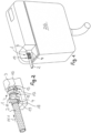
- a hose coupling 1 can be seen, which is provided at the hose end of a flexible hose line 2, which connects a water consumer or a water extraction point to a water supply.
- the hose coupling 1 has a coupling element 3 which is provided on the hose end of the flexible hose line 2 .
- the coupling element 3 can be releasably connected to a coupling counter-element 4 of the hose coupling 1 .
- At least one fluid channel 5, 6 is guided in the coupling element 3 and in the coupling counter-element 4, which fluid channels 5, 6 in the in the Figures 1, 2 and 7 to 9 shown holding position of the hose coupling 1 are liquid-tightly connected to each other.
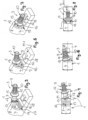
- the coupling element 3 has a coupling head 7, which is in the in the Figures 5 and 6 shown pivot position in a coupling head receptacle 8 on the coupling counter-element 4 can be used.
- the coupling element 3 and the coupling counter-element 4 are between the in Figure 5 and 6 pivot position shown and one in the Figures 7 to 9 shown holding position can be pivoted, in which holding position the coupling head 7 is held in the coupling head receptacle 8 and can be secured.
- the coupling element 3 is sleeve-shaped, with the of Flexible hose line 2 facing sleeve portion of the coupling element 3 is designed as a connecting piece 9, on which connecting piece 9 the associated hose end of the hose line 2 can be pushed.
- the coupling element 3 has a holding profile 10 on the outer circumference of the sleeve of its connecting piece 9 .
- the hose end of the hose line 2 can be attached to the connecting piece 9 by means of a enclosing hose end , pressed pinch or crimp sleeve 11 be secured.
- the coupling element 3 has an annular shoulder or annular flange 12 on the outer circumference, which serves as a sliding stop when the associated hose end of the hose line 2 is pushed on.
- the coupling element 3 has a ball head 13 on its sleeve end area facing away from the connecting piece 9, which is inserted into the as spherical socket designed coupling head recording 8 can be used.
- the coupling head 7 or the coupling head receptacle 8 can carry at least one circumferential seal which rests sealingly on the respective other element 8, 7 of the hose coupling 1.
- the coupling head 7 carries in a cross-sectional plane oriented transversely to the longitudinal axis of the coupling, preferably in the region of the equator of the Spherical shape of the ball head 13, a circumferential seal 14, which rests in the holding position on a wall of the coupling counter-element 4 that delimits the coupling head receptacle.
- a retaining flange 15 protrudes on the outer circumference, which in the retaining position at least partially engages behind a retaining wall 16, which retaining wall 16 is arranged in front of the coupling head receptacle 8 in the insertion direction Pf1 .
- a retaining groove 17 is provided in the insertion direction Pf1 in front of the coupling head receptacle 8 , while the groove wall facing away from the coupling head receptacle 8 is designed as a retaining wall 16 .
- the retaining groove 17 has a trapezoidal or conical cross-section, the greatest clear width of which is provided in the region of the groove opening.
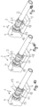
- At least one retaining eyelet 18 for a securing means is provided on the coupling counter-piece 4, with the aid of which the coupling element 3 can be held and secured on the coupling counter-element against swinging out of the holding position.
- the securing means can be threaded through the retaining eyelet in such a way that the securing means wrapped around the hose line 2 or the coupling element 3 passes through the retaining eyelet.
- a retaining clip 19 is provided on the coupling counter-element 4, which has a clip-in opening open at the top.
- FIG 10 shown embodiment of the hose coupling 1 also has a retaining clip 19, which is opposite to that in the Figures 1 and 2 shown embodiment, however, is simplified.
- a downwardly open retaining clip 20 is used as a securing means.
- the securing means is formed by a retaining clip 21 open at the side.
- a cable tie 22 is used as a securing means, which cable tie 22 passes through the retaining eyelet 18 and wraps around the hose line 2.
- the securing means is formed by an adhesive tape or tape 23 which can be releasably closed at least at its tape ends.
- the exemplary embodiment shown is the securing means in the form of a U-shaped bracket 24 , the free bracket ends of the U bracket 24 protruding in the hose line 2 being able to be connected and secured to one another by means of a screw connection 25 .
- the coupling element 3 can also be held magnetically on the counter-coupling element 4 .
- a Be attached magnet instead of the eyelet 18 a Be attached magnet, which interacts with a ferrule made of ferromagnetic material or with a ferromagnetic counterpart, which is attached to the hose line. Since these magnetically effective variants represent a relatively loose fixation compared to the attachment options presented above, this only makes sense for an application in which the hose coupling has to be removed regularly and at short intervals.
- the hose coupling 1 shown here can be used to advantage wherever fluids are to be guided, at least in sections, via a flexible hose line.
- the hose coupling 1 shown here can preferably be used in a sanitary water line.
- the hose coupling 1 can be arranged, for example, at the water inlet or water inlet of a toilet cistern 26 .
- the coupling counter-element is held immovably on the toilet cistern 26 , while the coupling element 2 of the hose coupling 1 is provided on the associated hose end of the flexible hose line 2 .
Landscapes
- Engineering & Computer Science (AREA)
- General Engineering & Computer Science (AREA)
- Mechanical Engineering (AREA)
- Quick-Acting Or Multi-Walled Pipe Joints (AREA)
Claims (15)
- Raccord de tuyau (1) avec un élément de raccord (3) qui est conçu pour pouvoir maintenir une extrémité de tuyau d'une conduite en tuyau flexible (2) et avec un élément de raccord homologue (4) qui peut être relié de façon détachable avec l'élément de raccord (3), au moins un canal de fluide (5, 6) étant guidé respectivement dans l'élément de raccord (3) et dans l'élément de raccord homologue (4) et les canaux de fluide (5, 6) de l'élément de raccord (3) ainsi que de l'élément de raccord homologue (4) étant reliés entre eux de façon étanche aux fluides dans une position de maintien de l'élément de raccord (3) et de l'élément de raccord homologue (4), dans lequel l'élément de raccord (3) ou l'élément de raccord homologue (4) présente une tête de raccord (7) qui peut être insérée, dans une position de pivotement, dans un réceptacle de tête de raccord de l'autre élément (4 ; 3) du raccord de tuyau (1), et l'élément de raccord (3) et l'élément de raccord homologue (4) peuvent pivoter l'un par rapport à l'autre entre la position de pivotement et la position de maintien, la tête de raccord (7) étant maintenue dans le réceptacle de tête de raccord (8) dans ladite position de maintien, caractérisé en ce que la tête de raccord (7) est configurée comme une tête sphérique et le réceptacle de tête de raccord (8) conformé comme une cavité articulaire.
- Raccord de tuyau selon la revendication 1, caractérisé en ce que le réceptacle de tête de raccord (8) est conformé comme une cavité articulaire sphérique.
- Raccord de tuyau selon la revendication 1 ou 2, caractérisé en ce que la tête de raccord (7) ou le réceptacle de tête de raccord (8) porte au moins un joint périphérique qui repose de façon étanche contre l'autre élément (8, 7) du raccord de tuyau (1).
- Raccord de tuyau selon une des revendications 1 à 3, caractérisé en ce que la tête de raccord (7) porte un joint périphérique (14) dans un plan transversal orienté transversalement par rapport à l'axe longitudinal de la tête de raccord, de préférence dans la région de l'équateur de la forme sphérique de la tête sphérique (13), lequel joint (14) repose de façon étanche, dans la position de maintien, contre une paroi délimitant le réceptacle de tête de raccord (8).
- Raccord de tuyau selon une des revendications 1 à 4, caractérisé en ce que l'élément de raccord (3) est configuré en forme de douille et que la région de l'élément de raccord orientée vers la conduite en tuyau flexible (2) est configurée comme un manchon de raccordement (9), l'extrémité de tuyau associée de la conduite en tuyau (2) pouvant glisser sur ledit manchon de raccordement (9).
- Raccord de tuyau selon la revendication 5, caractérisé en ce que l'élément de raccord (3) présente sur sa face périphérique extérieure une collerette annulaire (12) ou un épaulement annulaire qui fait office de butée de coulissement lors du coulissement de l'extrémité de tuyau associée de la conduite en tuyau (2).
- Raccord de tuyau selon la revendication 5 ou 6, caractérisé en ce que l'élément de raccord (3) porte la tête sphérique (13) sur sa région terminale en forme de douille opposée au manchon de raccordement (9).
- Raccord de tuyau selon une des revendications 5 à 7, caractérisé en ce que, dans la région en forme de douille de l'élément de raccord (3) saillant au-dessus de l'extrémité de tuyau de la conduite en tuyau (2), saille sur la face périphérique extérieure une collerette de maintien (15) qui, en position de maintien, vient en prise par derrière au moins en partie sur une paroi de maintien (16), laquelle paroi de maintien (16) est disposée.
- Raccord de tuyau selon la revendication 8, caractérisé en ce que devant le réceptacle de tête de raccord (9) dans la direction d'insertion (Pf1) est prévue une rainure de maintien (17) dont la paroi de rainure opposée au réceptacle de tête de raccord (8) est configurée comme une paroi de maintien (16).
- Raccord de tuyau selon la revendication 9, caractérisé en ce que la rainure de maintien (17) présente une section transversale trapézoïdale ou conique dont la plus grande largeur intérieure est prévue dans la région de l'ouverture de rainure.
- Raccord de tuyau selon une des revendications 1 à 10, caractérisé en ce qu'à ce raccord de tuyau (1) est associé au moins un moyen de sécurisation à l'aide duquel l'élément de raccord (3) peut être maintenu sur l'élément de raccord homologue (4) et sécurisé contre un pivotement hors de la position de maintien.
- Raccord de tuyau selon une des revendications 1 à 11, caractérisé en ce que le moyen de sécurisation est configuré comme un serre-câble (22), comme un ruban adhésif ou Tape (23), comme un ruban auto-agrippant, comme un étrier en U (24) ou comme une agrafe de maintien ou un clip de maintien (19, 20, 21).
- Raccord de tuyau selon la revendication 11 ou 12, caractérisé en ce que sur l'élément de raccord homologue (4) est prévu au moins un oeillet de maintien (18) pour le moyen de sécurisation et que le moyen de sécurisation entourant la conduite en tuyau (2) ou l'élément de raccord (3) traverse l'oeillet de maintien (18).
- Raccord de tuyau selon une des revendications 1 à 13, caractérisé en ce que ce raccord de tuyau (1) peut être utilisé dans une conduite d'eau sanitaire.
- Raccord de tuyau selon une des revendications 1 à 14, caractérisé en ce que ce raccord de tuyau (1) peut être agencé sur l'entrée d'eau ou la sortie d'eau d'une chasse d'eau de toilette (26).
Applications Claiming Priority (2)
| Application Number | Priority Date | Filing Date | Title |
|---|---|---|---|
| DE202020100810.2U DE202020100810U1 (de) | 2020-02-14 | 2020-02-14 | Schlauchkupplung |
| PCT/EP2020/087303 WO2021160328A1 (fr) | 2020-02-14 | 2020-12-18 | Raccord de tuyau |
Publications (2)
| Publication Number | Publication Date |
|---|---|
| EP4034793A1 EP4034793A1 (fr) | 2022-08-03 |
| EP4034793B1 true EP4034793B1 (fr) | 2023-06-07 |
Family
ID=74175791
Family Applications (1)
| Application Number | Title | Priority Date | Filing Date |
|---|---|---|---|
| EP20838985.8A Active EP4034793B1 (fr) | 2020-02-14 | 2020-12-18 | Raccord de tuyau |
Country Status (5)
| Country | Link |
|---|---|
| EP (1) | EP4034793B1 (fr) |
| CN (1) | CN114981580B (fr) |
| DE (1) | DE202020100810U1 (fr) |
| ES (1) | ES2955361T3 (fr) |
| WO (1) | WO2021160328A1 (fr) |
Family Cites Families (9)
| Publication number | Priority date | Publication date | Assignee | Title |
|---|---|---|---|---|
| CH386940A (de) * | 1961-09-14 | 1965-01-15 | Gebert & Cie Armaturen & Appar | Ablaufvorrichtung an Unterputz-Spülkasten |
| JPH10292886A (ja) * | 1997-04-18 | 1998-11-04 | Fushiman Kk | ボールジョイント |
| AU2010292369B9 (en) * | 2009-09-11 | 2015-03-19 | Victaulic Company | Flexible assembly for sprinklers |
| DE102010014686A1 (de) * | 2010-04-12 | 2011-10-13 | Röhrenwerk Kupferdreh Carl Hamm GmbH | Rohrkupplung für Hochdruckrohre |
| JP6706727B2 (ja) * | 2014-07-03 | 2020-06-10 | ダイセン株式会社 | 流体継手 |
| EP3112737B1 (fr) * | 2015-07-03 | 2019-09-04 | MANN+HUMMEL GmbH | Agencement de couplage avec des corps de couplage et patte de raccordement pour tuyaux |
| DE102015014816B4 (de) * | 2015-11-14 | 2018-01-18 | Audi Ag | Kupplungselement zum Verbinden fluidführender Leitungen sowie entsprechende Kupplungsanordnung |
| DE202018101119U1 (de) * | 2018-02-28 | 2019-05-31 | Neoperl Gmbh | Kugelgelenk |
| CN208429043U (zh) * | 2018-06-26 | 2019-01-25 | 郑州比克电池有限公司 | 一种电动汽车电池包模组线束固定支架 |
-
2020
- 2020-02-14 DE DE202020100810.2U patent/DE202020100810U1/de active Active
- 2020-12-18 CN CN202080091609.8A patent/CN114981580B/zh active Active
- 2020-12-18 ES ES20838985T patent/ES2955361T3/es active Active
- 2020-12-18 WO PCT/EP2020/087303 patent/WO2021160328A1/fr not_active Ceased
- 2020-12-18 EP EP20838985.8A patent/EP4034793B1/fr active Active
Also Published As
| Publication number | Publication date |
|---|---|
| WO2021160328A1 (fr) | 2021-08-19 |
| CN114981580A (zh) | 2022-08-30 |
| CN114981580B (zh) | 2025-02-07 |
| DE202020100810U1 (de) | 2021-05-17 |
| EP4034793A1 (fr) | 2022-08-03 |
| ES2955361T3 (es) | 2023-11-30 |
Similar Documents
| Publication | Publication Date | Title |
|---|---|---|
| DE69203429T2 (de) | Verbesserungen an Rohrverbindungen von koaxialen Rohren. | |
| EP2964992B1 (fr) | Raccord à emboîtement pour deux tubes et procédé de montage du raccord à emboîtement | |
| EP0787864B1 (fr) | Dispositif de sécurité sanitaire | |
| EP2384382B9 (fr) | Régulateur de débit | |
| DE9105229U1 (de) | Ventilvorrichtung für einen Katheter | |
| EP3169853B1 (fr) | Tuyau flexible | |
| EP2582889B1 (fr) | Robinetterie de distribution d'eau à rotule | |
| DE202013002188U1 (de) | Sanitäres Einbauteil, Innenschlauchanordnung für eine Sanitärarmatur und Sanitärarmatur | |
| DE202010009135U1 (de) | Dichtring, Durchflussmengenregler sowie Brausearmatur mit einem Durchflussmengenregler | |
| DE202020104394U1 (de) | Sanitärschnittstelle, Sanitärarmatur, Baukasten zur Herstellung einer Sanitärschnittstelle und Verwendung einer Sanitärschnittstelle | |
| EP1264127B1 (fr) | Robinet d'arret rotatif pour embout d'enfichage avec raccord coude | |
| EP3759285B9 (fr) | Joint sphérique | |
| EP2453157B1 (fr) | Système de raccord pour l'installation d'un appareil de conduite de l'eau | |
| EP1672265A1 (fr) | Dispositif de raccordement pour une conduite de fluide, notamment pour un robinet | |
| DE4205142C1 (fr) | ||
| EP4034793B1 (fr) | Raccord de tuyau | |
| EP2975311B1 (fr) | Raccord a vis pour tuyaux souples | |
| DE102010023962A1 (de) | Dichtring, Durchflussmengenregler sowie Brausearmatur mit einem Durchflussmengenregler | |
| DE102020103960B4 (de) | Verwendung einer Schlauchkupplung | |
| EP3205783B1 (fr) | Anti-refouleur sanitaire | |
| DE102012221675A1 (de) | Sanitärarmatur und Fluidleitung hierfür | |
| DE20303522U1 (de) | Absperrventil | |
| DE2426790A1 (de) | Schnellanschluss fuer wasserhaehne | |
| DE102014010521A1 (de) | Schlauchanschluss | |
| AT211115B (de) | Rohrverbinder für Flüssigkeitsrohrleitungen, insbesondere für Aluminium- oder Kunststoffrohre von fliegenden Bewässerungsrohrleitungen |
Legal Events
| Date | Code | Title | Description |
|---|---|---|---|
| STAA | Information on the status of an ep patent application or granted ep patent |
Free format text: STATUS: UNKNOWN |
|
| STAA | Information on the status of an ep patent application or granted ep patent |
Free format text: STATUS: THE INTERNATIONAL PUBLICATION HAS BEEN MADE |
|
| PUAI | Public reference made under article 153(3) epc to a published international application that has entered the european phase |
Free format text: ORIGINAL CODE: 0009012 |
|
| STAA | Information on the status of an ep patent application or granted ep patent |
Free format text: STATUS: REQUEST FOR EXAMINATION WAS MADE |
|
| 17P | Request for examination filed |
Effective date: 20220425 |
|
| AK | Designated contracting states |
Kind code of ref document: A1 Designated state(s): AL AT BE BG CH CY CZ DE DK EE ES FI FR GB GR HR HU IE IS IT LI LT LU LV MC MK MT NL NO PL PT RO RS SE SI SK SM TR |
|
| GRAP | Despatch of communication of intention to grant a patent |
Free format text: ORIGINAL CODE: EPIDOSNIGR1 |
|
| STAA | Information on the status of an ep patent application or granted ep patent |
Free format text: STATUS: GRANT OF PATENT IS INTENDED |
|
| INTG | Intention to grant announced |
Effective date: 20221025 |
|
| GRAS | Grant fee paid |
Free format text: ORIGINAL CODE: EPIDOSNIGR3 |
|
| DAV | Request for validation of the european patent (deleted) | ||
| DAX | Request for extension of the european patent (deleted) | ||
| GRAA | (expected) grant |
Free format text: ORIGINAL CODE: 0009210 |
|
| STAA | Information on the status of an ep patent application or granted ep patent |
Free format text: STATUS: THE PATENT HAS BEEN GRANTED |
|
| AK | Designated contracting states |
Kind code of ref document: B1 Designated state(s): AL AT BE BG CH CY CZ DE DK EE ES FI FR GB GR HR HU IE IS IT LI LT LU LV MC MK MT NL NO PL PT RO RS SE SI SK SM TR |
|
| REG | Reference to a national code |
Ref country code: GB Ref legal event code: FG4D Free format text: NOT ENGLISH |
|
| REG | Reference to a national code |
Ref country code: CH Ref legal event code: EP Ref country code: AT Ref legal event code: REF Ref document number: 1576023 Country of ref document: AT Kind code of ref document: T Effective date: 20230615 Ref country code: DE Ref legal event code: R096 Ref document number: 502020003747 Country of ref document: DE |
|
| REG | Reference to a national code |
Ref country code: LT Ref legal event code: MG9D |
|
| REG | Reference to a national code |
Ref country code: NL Ref legal event code: MP Effective date: 20230607 |
|
| PG25 | Lapsed in a contracting state [announced via postgrant information from national office to epo] |
Ref country code: SE Free format text: LAPSE BECAUSE OF FAILURE TO SUBMIT A TRANSLATION OF THE DESCRIPTION OR TO PAY THE FEE WITHIN THE PRESCRIBED TIME-LIMIT Effective date: 20230607 Ref country code: NO Free format text: LAPSE BECAUSE OF FAILURE TO SUBMIT A TRANSLATION OF THE DESCRIPTION OR TO PAY THE FEE WITHIN THE PRESCRIBED TIME-LIMIT Effective date: 20230907 |
|
| PG25 | Lapsed in a contracting state [announced via postgrant information from national office to epo] |
Ref country code: RS Free format text: LAPSE BECAUSE OF FAILURE TO SUBMIT A TRANSLATION OF THE DESCRIPTION OR TO PAY THE FEE WITHIN THE PRESCRIBED TIME-LIMIT Effective date: 20230607 Ref country code: NL Free format text: LAPSE BECAUSE OF FAILURE TO SUBMIT A TRANSLATION OF THE DESCRIPTION OR TO PAY THE FEE WITHIN THE PRESCRIBED TIME-LIMIT Effective date: 20230607 Ref country code: LV Free format text: LAPSE BECAUSE OF FAILURE TO SUBMIT A TRANSLATION OF THE DESCRIPTION OR TO PAY THE FEE WITHIN THE PRESCRIBED TIME-LIMIT Effective date: 20230607 Ref country code: LT Free format text: LAPSE BECAUSE OF FAILURE TO SUBMIT A TRANSLATION OF THE DESCRIPTION OR TO PAY THE FEE WITHIN THE PRESCRIBED TIME-LIMIT Effective date: 20230607 Ref country code: HR Free format text: LAPSE BECAUSE OF FAILURE TO SUBMIT A TRANSLATION OF THE DESCRIPTION OR TO PAY THE FEE WITHIN THE PRESCRIBED TIME-LIMIT Effective date: 20230607 Ref country code: GR Free format text: LAPSE BECAUSE OF FAILURE TO SUBMIT A TRANSLATION OF THE DESCRIPTION OR TO PAY THE FEE WITHIN THE PRESCRIBED TIME-LIMIT Effective date: 20230908 |
|
| REG | Reference to a national code |
Ref country code: ES Ref legal event code: FG2A Ref document number: 2955361 Country of ref document: ES Kind code of ref document: T3 Effective date: 20231130 |
|
| PG25 | Lapsed in a contracting state [announced via postgrant information from national office to epo] |
Ref country code: FI Free format text: LAPSE BECAUSE OF FAILURE TO SUBMIT A TRANSLATION OF THE DESCRIPTION OR TO PAY THE FEE WITHIN THE PRESCRIBED TIME-LIMIT Effective date: 20230607 |
|
| PG25 | Lapsed in a contracting state [announced via postgrant information from national office to epo] |
Ref country code: SK Free format text: LAPSE BECAUSE OF FAILURE TO SUBMIT A TRANSLATION OF THE DESCRIPTION OR TO PAY THE FEE WITHIN THE PRESCRIBED TIME-LIMIT Effective date: 20230607 |
|
| PG25 | Lapsed in a contracting state [announced via postgrant information from national office to epo] |
Ref country code: IS Free format text: LAPSE BECAUSE OF FAILURE TO SUBMIT A TRANSLATION OF THE DESCRIPTION OR TO PAY THE FEE WITHIN THE PRESCRIBED TIME-LIMIT Effective date: 20231007 |
|
| PG25 | Lapsed in a contracting state [announced via postgrant information from national office to epo] |
Ref country code: SM Free format text: LAPSE BECAUSE OF FAILURE TO SUBMIT A TRANSLATION OF THE DESCRIPTION OR TO PAY THE FEE WITHIN THE PRESCRIBED TIME-LIMIT Effective date: 20230607 Ref country code: SK Free format text: LAPSE BECAUSE OF FAILURE TO SUBMIT A TRANSLATION OF THE DESCRIPTION OR TO PAY THE FEE WITHIN THE PRESCRIBED TIME-LIMIT Effective date: 20230607 Ref country code: RO Free format text: LAPSE BECAUSE OF FAILURE TO SUBMIT A TRANSLATION OF THE DESCRIPTION OR TO PAY THE FEE WITHIN THE PRESCRIBED TIME-LIMIT Effective date: 20230607 Ref country code: PT Free format text: LAPSE BECAUSE OF FAILURE TO SUBMIT A TRANSLATION OF THE DESCRIPTION OR TO PAY THE FEE WITHIN THE PRESCRIBED TIME-LIMIT Effective date: 20231009 Ref country code: IS Free format text: LAPSE BECAUSE OF FAILURE TO SUBMIT A TRANSLATION OF THE DESCRIPTION OR TO PAY THE FEE WITHIN THE PRESCRIBED TIME-LIMIT Effective date: 20231007 Ref country code: EE Free format text: LAPSE BECAUSE OF FAILURE TO SUBMIT A TRANSLATION OF THE DESCRIPTION OR TO PAY THE FEE WITHIN THE PRESCRIBED TIME-LIMIT Effective date: 20230607 Ref country code: CZ Free format text: LAPSE BECAUSE OF FAILURE TO SUBMIT A TRANSLATION OF THE DESCRIPTION OR TO PAY THE FEE WITHIN THE PRESCRIBED TIME-LIMIT Effective date: 20230607 |
|
| PG25 | Lapsed in a contracting state [announced via postgrant information from national office to epo] |
Ref country code: PL Free format text: LAPSE BECAUSE OF FAILURE TO SUBMIT A TRANSLATION OF THE DESCRIPTION OR TO PAY THE FEE WITHIN THE PRESCRIBED TIME-LIMIT Effective date: 20230607 |
|
| REG | Reference to a national code |
Ref country code: DE Ref legal event code: R097 Ref document number: 502020003747 Country of ref document: DE |
|
| PLBE | No opposition filed within time limit |
Free format text: ORIGINAL CODE: 0009261 |
|
| STAA | Information on the status of an ep patent application or granted ep patent |
Free format text: STATUS: NO OPPOSITION FILED WITHIN TIME LIMIT |
|
| PG25 | Lapsed in a contracting state [announced via postgrant information from national office to epo] |
Ref country code: DK Free format text: LAPSE BECAUSE OF FAILURE TO SUBMIT A TRANSLATION OF THE DESCRIPTION OR TO PAY THE FEE WITHIN THE PRESCRIBED TIME-LIMIT Effective date: 20230607 |
|
| PG25 | Lapsed in a contracting state [announced via postgrant information from national office to epo] |
Ref country code: SI Free format text: LAPSE BECAUSE OF FAILURE TO SUBMIT A TRANSLATION OF THE DESCRIPTION OR TO PAY THE FEE WITHIN THE PRESCRIBED TIME-LIMIT Effective date: 20230607 |
|
| 26N | No opposition filed |
Effective date: 20240308 |
|
| PG25 | Lapsed in a contracting state [announced via postgrant information from national office to epo] |
Ref country code: SI Free format text: LAPSE BECAUSE OF FAILURE TO SUBMIT A TRANSLATION OF THE DESCRIPTION OR TO PAY THE FEE WITHIN THE PRESCRIBED TIME-LIMIT Effective date: 20230607 |
|
| REG | Reference to a national code |
Ref country code: CH Ref legal event code: PL |
|
| PG25 | Lapsed in a contracting state [announced via postgrant information from national office to epo] |
Ref country code: LU Free format text: LAPSE BECAUSE OF NON-PAYMENT OF DUE FEES Effective date: 20231218 |
|
| PG25 | Lapsed in a contracting state [announced via postgrant information from national office to epo] |
Ref country code: MC Free format text: LAPSE BECAUSE OF FAILURE TO SUBMIT A TRANSLATION OF THE DESCRIPTION OR TO PAY THE FEE WITHIN THE PRESCRIBED TIME-LIMIT Effective date: 20230607 |
|
| REG | Reference to a national code |
Ref country code: BE Ref legal event code: MM Effective date: 20231231 |
|
| PG25 | Lapsed in a contracting state [announced via postgrant information from national office to epo] |
Ref country code: MC Free format text: LAPSE BECAUSE OF FAILURE TO SUBMIT A TRANSLATION OF THE DESCRIPTION OR TO PAY THE FEE WITHIN THE PRESCRIBED TIME-LIMIT Effective date: 20230607 Ref country code: LU Free format text: LAPSE BECAUSE OF NON-PAYMENT OF DUE FEES Effective date: 20231218 |
|
| REG | Reference to a national code |
Ref country code: IE Ref legal event code: MM4A |
|
| PG25 | Lapsed in a contracting state [announced via postgrant information from national office to epo] |
Ref country code: IE Free format text: LAPSE BECAUSE OF NON-PAYMENT OF DUE FEES Effective date: 20231218 |
|
| PG25 | Lapsed in a contracting state [announced via postgrant information from national office to epo] |
Ref country code: BE Free format text: LAPSE BECAUSE OF NON-PAYMENT OF DUE FEES Effective date: 20231231 |
|
| PG25 | Lapsed in a contracting state [announced via postgrant information from national office to epo] |
Ref country code: FR Free format text: LAPSE BECAUSE OF NON-PAYMENT OF DUE FEES Effective date: 20231231 |
|
| PG25 | Lapsed in a contracting state [announced via postgrant information from national office to epo] |
Ref country code: CH Free format text: LAPSE BECAUSE OF NON-PAYMENT OF DUE FEES Effective date: 20231231 |
|
| PG25 | Lapsed in a contracting state [announced via postgrant information from national office to epo] |
Ref country code: IE Free format text: LAPSE BECAUSE OF NON-PAYMENT OF DUE FEES Effective date: 20231218 Ref country code: FR Free format text: LAPSE BECAUSE OF NON-PAYMENT OF DUE FEES Effective date: 20231231 Ref country code: CH Free format text: LAPSE BECAUSE OF NON-PAYMENT OF DUE FEES Effective date: 20231231 Ref country code: BE Free format text: LAPSE BECAUSE OF NON-PAYMENT OF DUE FEES Effective date: 20231231 |
|
| PG25 | Lapsed in a contracting state [announced via postgrant information from national office to epo] |
Ref country code: BG Free format text: LAPSE BECAUSE OF FAILURE TO SUBMIT A TRANSLATION OF THE DESCRIPTION OR TO PAY THE FEE WITHIN THE PRESCRIBED TIME-LIMIT Effective date: 20230607 |
|
| PG25 | Lapsed in a contracting state [announced via postgrant information from national office to epo] |
Ref country code: BG Free format text: LAPSE BECAUSE OF FAILURE TO SUBMIT A TRANSLATION OF THE DESCRIPTION OR TO PAY THE FEE WITHIN THE PRESCRIBED TIME-LIMIT Effective date: 20230607 |
|
| REG | Reference to a national code |
Ref country code: ES Ref legal event code: FD2A Effective date: 20250124 |
|
| PG25 | Lapsed in a contracting state [announced via postgrant information from national office to epo] |
Ref country code: ES Free format text: LAPSE BECAUSE OF NON-PAYMENT OF DUE FEES Effective date: 20231219 |
|
| PG25 | Lapsed in a contracting state [announced via postgrant information from national office to epo] |
Ref country code: CY Free format text: LAPSE BECAUSE OF FAILURE TO SUBMIT A TRANSLATION OF THE DESCRIPTION OR TO PAY THE FEE WITHIN THE PRESCRIBED TIME-LIMIT; INVALID AB INITIO Effective date: 20201218 |
|
| PG25 | Lapsed in a contracting state [announced via postgrant information from national office to epo] |
Ref country code: HU Free format text: LAPSE BECAUSE OF FAILURE TO SUBMIT A TRANSLATION OF THE DESCRIPTION OR TO PAY THE FEE WITHIN THE PRESCRIBED TIME-LIMIT; INVALID AB INITIO Effective date: 20201218 |
|
| GBPC | Gb: european patent ceased through non-payment of renewal fee |
Effective date: 20241218 |
|
| PG25 | Lapsed in a contracting state [announced via postgrant information from national office to epo] |
Ref country code: GB Free format text: LAPSE BECAUSE OF NON-PAYMENT OF DUE FEES Effective date: 20241218 |
|
| PGFP | Annual fee paid to national office [announced via postgrant information from national office to epo] |
Ref country code: AT Payment date: 20260113 Year of fee payment: 5 |
|
| PGFP | Annual fee paid to national office [announced via postgrant information from national office to epo] |
Ref country code: DE Payment date: 20260227 Year of fee payment: 6 |
|
| PGFP | Annual fee paid to national office [announced via postgrant information from national office to epo] |
Ref country code: IT Payment date: 20251231 Year of fee payment: 6 |