EP4034807B1 - Leuchte mit bereich zur flächigen lichtabgabe - Google Patents
Leuchte mit bereich zur flächigen lichtabgabe Download PDFInfo
- Publication number
- EP4034807B1 EP4034807B1 EP20745124.6A EP20745124A EP4034807B1 EP 4034807 B1 EP4034807 B1 EP 4034807B1 EP 20745124 A EP20745124 A EP 20745124A EP 4034807 B1 EP4034807 B1 EP 4034807B1
- Authority
- EP
- European Patent Office
- Prior art keywords
- light
- cover
- luminaire according
- luminaire
- lamp
- Prior art date
- Legal status (The legal status is an assumption and is not a legal conclusion. Google has not performed a legal analysis and makes no representation as to the accuracy of the status listed.)
- Active
Links
Images


Classifications
-
- F—MECHANICAL ENGINEERING; LIGHTING; HEATING; WEAPONS; BLASTING
- F21—LIGHTING
- F21S—NON-PORTABLE LIGHTING DEVICES; SYSTEMS THEREOF; VEHICLE LIGHTING DEVICES SPECIALLY ADAPTED FOR VEHICLE EXTERIORS
- F21S4/00—Lighting devices or systems using a string or strip of light sources
- F21S4/20—Lighting devices or systems using a string or strip of light sources with light sources held by or within elongate supports
- F21S4/28—Lighting devices or systems using a string or strip of light sources with light sources held by or within elongate supports rigid, e.g. LED bars
-
- F—MECHANICAL ENGINEERING; LIGHTING; HEATING; WEAPONS; BLASTING
- F21—LIGHTING
- F21V—FUNCTIONAL FEATURES OR DETAILS OF LIGHTING DEVICES OR SYSTEMS THEREOF; STRUCTURAL COMBINATIONS OF LIGHTING DEVICES WITH OTHER ARTICLES, NOT OTHERWISE PROVIDED FOR
- F21V13/00—Producing particular characteristics or distribution of the light emitted by means of a combination of elements specified in two or more of main groups F21V1/00 - F21V11/00
-
- F—MECHANICAL ENGINEERING; LIGHTING; HEATING; WEAPONS; BLASTING
- F21—LIGHTING
- F21S—NON-PORTABLE LIGHTING DEVICES; SYSTEMS THEREOF; VEHICLE LIGHTING DEVICES SPECIALLY ADAPTED FOR VEHICLE EXTERIORS
- F21S8/00—Lighting devices intended for fixed installation
- F21S8/04—Lighting devices intended for fixed installation intended only for mounting on a ceiling or the like overhead structures
-
- F—MECHANICAL ENGINEERING; LIGHTING; HEATING; WEAPONS; BLASTING
- F21—LIGHTING
- F21V—FUNCTIONAL FEATURES OR DETAILS OF LIGHTING DEVICES OR SYSTEMS THEREOF; STRUCTURAL COMBINATIONS OF LIGHTING DEVICES WITH OTHER ARTICLES, NOT OTHERWISE PROVIDED FOR
- F21V11/00—Screens not covered by groups F21V1/00, F21V3/00, F21V7/00 or F21V9/00
-
- F—MECHANICAL ENGINEERING; LIGHTING; HEATING; WEAPONS; BLASTING
- F21—LIGHTING
- F21V—FUNCTIONAL FEATURES OR DETAILS OF LIGHTING DEVICES OR SYSTEMS THEREOF; STRUCTURAL COMBINATIONS OF LIGHTING DEVICES WITH OTHER ARTICLES, NOT OTHERWISE PROVIDED FOR
- F21V17/00—Fastening of component parts of lighting devices, e.g. shades, globes, refractors, reflectors, filters, screens, grids or protective cages
- F21V17/10—Fastening of component parts of lighting devices, e.g. shades, globes, refractors, reflectors, filters, screens, grids or protective cages characterised by specific fastening means or way of fastening
- F21V17/16—Fastening of component parts of lighting devices, e.g. shades, globes, refractors, reflectors, filters, screens, grids or protective cages characterised by specific fastening means or way of fastening by deformation of parts; Snap action mounting
- F21V17/162—Fastening of component parts of lighting devices, e.g. shades, globes, refractors, reflectors, filters, screens, grids or protective cages characterised by specific fastening means or way of fastening by deformation of parts; Snap action mounting the parts being subjected to traction or compression, e.g. coil springs
-
- F—MECHANICAL ENGINEERING; LIGHTING; HEATING; WEAPONS; BLASTING
- F21—LIGHTING
- F21V—FUNCTIONAL FEATURES OR DETAILS OF LIGHTING DEVICES OR SYSTEMS THEREOF; STRUCTURAL COMBINATIONS OF LIGHTING DEVICES WITH OTHER ARTICLES, NOT OTHERWISE PROVIDED FOR
- F21V3/00—Globes; Bowls; Cover glasses
- F21V3/04—Globes; Bowls; Cover glasses characterised by materials, surface treatments or coatings
- F21V3/049—Patterns or structured surfaces for diffusing light, e.g. frosted surfaces
-
- F—MECHANICAL ENGINEERING; LIGHTING; HEATING; WEAPONS; BLASTING
- F21—LIGHTING
- F21V—FUNCTIONAL FEATURES OR DETAILS OF LIGHTING DEVICES OR SYSTEMS THEREOF; STRUCTURAL COMBINATIONS OF LIGHTING DEVICES WITH OTHER ARTICLES, NOT OTHERWISE PROVIDED FOR
- F21V5/00—Refractors for light sources
- F21V5/002—Refractors for light sources using microoptical elements for redirecting or diffusing light
- F21V5/005—Refractors for light sources using microoptical elements for redirecting or diffusing light using microprisms
-
- F—MECHANICAL ENGINEERING; LIGHTING; HEATING; WEAPONS; BLASTING
- F21—LIGHTING
- F21V—FUNCTIONAL FEATURES OR DETAILS OF LIGHTING DEVICES OR SYSTEMS THEREOF; STRUCTURAL COMBINATIONS OF LIGHTING DEVICES WITH OTHER ARTICLES, NOT OTHERWISE PROVIDED FOR
- F21V5/00—Refractors for light sources
- F21V5/008—Combination of two or more successive refractors along an optical axis
-
- F—MECHANICAL ENGINEERING; LIGHTING; HEATING; WEAPONS; BLASTING
- F21—LIGHTING
- F21V—FUNCTIONAL FEATURES OR DETAILS OF LIGHTING DEVICES OR SYSTEMS THEREOF; STRUCTURAL COMBINATIONS OF LIGHTING DEVICES WITH OTHER ARTICLES, NOT OTHERWISE PROVIDED FOR
- F21V5/00—Refractors for light sources
- F21V5/02—Refractors for light sources of prismatic shape
-
- G—PHYSICS
- G02—OPTICS
- G02B—OPTICAL ELEMENTS, SYSTEMS OR APPARATUS
- G02B5/00—Optical elements other than lenses
- G02B5/02—Diffusing elements; Afocal elements
- G02B5/0205—Diffusing elements; Afocal elements characterised by the diffusing properties
- G02B5/021—Diffusing elements; Afocal elements characterised by the diffusing properties the diffusion taking place at the element's surface, e.g. by means of surface roughening or microprismatic structures
-
- F—MECHANICAL ENGINEERING; LIGHTING; HEATING; WEAPONS; BLASTING
- F21—LIGHTING
- F21Y—INDEXING SCHEME ASSOCIATED WITH SUBCLASSES F21K, F21L, F21S and F21V, RELATING TO THE FORM OR THE KIND OF THE LIGHT SOURCES OR OF THE COLOUR OF THE LIGHT EMITTED
- F21Y2103/00—Elongate light sources, e.g. fluorescent tubes
- F21Y2103/10—Elongate light sources, e.g. fluorescent tubes comprising a linear array of point-like light-generating elements
-
- F—MECHANICAL ENGINEERING; LIGHTING; HEATING; WEAPONS; BLASTING
- F21—LIGHTING
- F21Y—INDEXING SCHEME ASSOCIATED WITH SUBCLASSES F21K, F21L, F21S and F21V, RELATING TO THE FORM OR THE KIND OF THE LIGHT SOURCES OR OF THE COLOUR OF THE LIGHT EMITTED
- F21Y2115/00—Light-generating elements of semiconductor light sources
- F21Y2115/10—Light-emitting diodes [LED]
Definitions
- the present invention relates to a luminaire according to the preamble of claim 1, which has lighting means, as well as a cover which forms at least one flat area for emitting light.
- the WO 02/44612 A2 describes a surface light, whereby the emitting surface can have light-scattering structures.
- an additional light equalization means can be arranged between the light sources and the emitting surface, which ensures additional scattering of the light and can be made of a film.
- Modern lights are often designed in such a way that they not only emit light in one way, but also emit another or additional light. While the primary light output serves to fulfil the task of the light in terms of its area of application, the additional light output is used to create a so-called accent light or to brighten an additional area in order to improve the overall appearance of the light itself and the illuminated area. The primary light output is then used, for example, to specifically illuminate a certain area below the light, e.g. for work purposes, or to specifically brighten areas below the light.
- a lamp which emits light in different ways in the sense of the above explanations is sold by the applicant under the name "ECOOS".
- ECOOS is a lamp which extends longitudinally and in which the light sources are enclosed by a roughly U-shaped cover.
- the underside of the cover is used to emit directed light to illuminate workstations or the like, while a smaller proportion of the light is also emitted via the side walls of the cover in order to improve the overall appearance of the lamp.
- Perforated aluminum reflectors are arranged in front of the side walls of the cover, the hole pattern of which allows some of the light to pass through, which is then emitted via the side walls of the cover.
- the aluminum reflectors reduce the proportion of light emitted via the side walls in such a way that there is no risk of glare. Furthermore, the fact that the reflectors are a certain distance from the side walls of the cover creates a so-called depth effect, so that the lamp as a whole appears to be a brilliant object. Despite everything, work spaces or communication areas can be efficiently illuminated with the help of this lamp, since a large part of the light generated by the lamps is emitted in the desired direction towards the underside.
- the lamp mentioned above is characterized by its particularly attractive light output and the resulting appearance.
- the use of the perforated aluminum reflectors responsible for the appearance is associated with certain disadvantages.
- the present invention is therefore based on the object of providing a novel possibility of achieving a light output for a luminaire that is comparable to that described above, but reducing the effort required for this.
- the light according to the invention is intended to at least partially produce a light output that produces the above-mentioned depth effect in an observer.
- the area of a light-emitting element intended for the corresponding light output consists of a transparent material and is provided with a structure on one side.
- a plate-shaped light-influencing element formed by a plastic film is arranged between the lighting means and the flat area for light output, which consists of a translucent material but is printed with a pattern.
- a lamp with lighting means and with a cover which forms at least one flat area for emitting light, wherein the flat area for emitting light consists of a transparent material and is provided with a structure on at least one side, and wherein a plate-shaped light-influencing element formed by a plastic film is arranged between the lighting means and the flat area for emitting light, which consists of a translucent material and is printed with a pattern.
- the film forming the light-influencing element is clamped into the cover in such a way that the light-influencing element is at a distance from the cover.
- the structure of the cover is preferably formed on the inside of the flat area for emitting light.
- the outside of this area of the cover is ideally completely smooth, which not only prevents the accumulation of dust and dirt, but also improves the appearance of the lamp.
- the light extends along a longitudinal axis and the structure of the cover is designed to be translationally invariant parallel to the longitudinal axis.
- the structure can be designed in a Fresnel-like manner or can be formed by a prism structure extending in the longitudinal direction. This can have triangular, in particular sawtooth-like, elevations in cross section.
- the plate-shaped light-influencing element, which is printed with the pattern, is formed according to the invention by a plastic film. Ideally, this has a certain thickness and thus inherent stability, so that it can be stored in a simple manner clamped into the cover according to the invention.
- the pattern with which the film is printed is preferably formed periodically in the longitudinal direction of the lamp. In a direction perpendicular to the longitudinal direction, however, the pattern can be provided to change.
- the cover of the lamp according to the invention is preferably U-shaped with two side walls and a bottom wall connecting the side wall, whereby both side walls form flat areas for emitting light and are designed as explained above in the sense of the present invention.
- the bottom surface of the cover is preferably also translucent. designed, but intended for the primary light emission of the luminaire.
- Various measures can be provided here to influence the light emitted, which ensure that the light emitted fulfills the lighting task of the luminaire.
- the solution according to the invention makes it possible to realize a luminaire which, in terms of its light emission properties, is at least equivalent to the previously known luminaire described above, although the positive appearance of the luminaire can be realized with significantly less effort and, in particular, also more cost-effectively.
- the lamp generally provided with the reference number 100 in the figures, is elongated and in the embodiment shown is designed as a pendant lamp. In a comparable manner, however, it would also be conceivable for the lamp 100 to be mounted on the ceiling.
- the central holding element of the lamp 100 is a longitudinally extending carrier 10, which serves to hold all other components of the lamp 100 and to which corresponding suspension elements 110 are also attached.
- the carrier 100 serves to hold the lamps required for generating light and any necessary operating equipment that converts a supply voltage fed to the lamp 100 into a voltage suitable for operating the lamps. This applies in particular to the preferred case in which LED boards extending in the longitudinal direction are used as lamps, which have a large number of LEDs arranged one behind the other.
- a cover 20 is attached to the carrier 10, which in cross section has the Figure 2 recognizable shape. It is therefore an approximately U-shaped cross-sectional shape that has a base surface 21 and two side walls 25. On its upper side facing the carrier 10, however, the cover 20 is additionally designed with inward-facing wall areas 23 that extend as far as the carrier 10. Overall, the cover 20 thus encloses an elongated rectangular receiving space in which the components of the lamp 100 responsible for generating and emitting light are arranged.
- the luminaire 100 is closed off by corresponding front elements 15, which are plugged onto the open end areas of the cover 20 and connected to it. This creates space inside the Cover 20 is completely enclosed so that the luminaire 100 can also meet the requirements of corresponding so-called protection classes, i.e. is appropriately protected against the ingress of dust, dirt and/or moisture.
- the cover 20 consists entirely of a translucent, preferably clear material. Accordingly, it is intended that light is emitted across all surfaces, so that - with regard to the longitudinal axis of the lamp 100 - light can be emitted across 360°.
- the main light emission should be via the floor surface 21, so that there is direct light emission towards the underside, which is used, for example, to illuminate work surfaces or workplaces or objects located below the lamp 100.
- the two upper wall areas 23 of the cover 20, on the other hand, serve to emit a small proportion of the light upwards, for example, towards the ceiling of a room in which the lamp 100 is mounted. This can slightly brighten the ceiling area above the lamp 100. This portion of the light emitted indirectly into the room is also directed onto the work surface via reflections on the room boundary surfaces and, as a supplement to the other light components, is largely responsible for a pleasant room atmosphere.
- a structure or the like can be provided on the surface of the wall sections 23 of the cover 20 facing the interior in order to achieve a better distribution of the light emitted upwards. Measures described in more detail below are also provided for the light emission towards the underside in order to influence the light in the desired manner.
- an optical element 40 is arranged within the space enclosed by the cover 20, which is formed, for example, from a light-scattering material and which serves to reflect the light of the Figure 2 schematically illustrated illuminants 18, 19 before being emitted, in particular via the bottom side 21 of the cover 20.
- the light-scattering element 40 has an approximately H-shaped cross-section with a Horizontal surface 41, from which two arms 42 extend obliquely downwards essentially to the lower corners of the cover 20.
- the element 40 is an integral part of the cover 20 produced by the extrusion process and thus connected to it at the lower ends, as Figure 2
- the various side walls 21, 23, 25 of the cover are made of a clear material
- the light-influencing element 40 is preferably made of a light-scattering material throughout.
- upwardly extending webs 43 are provided on the side areas of the horizontal surface 41.
- the light influencing element 40 then serves to resolve the individual LEDs 19 as individual light points. This is particularly important for the light emission via the base surface 21 of the cover 20, since the aim here is to achieve the most uniform possible illumination of the area to be illuminated and, furthermore, the LEDs should no longer be perceptible as individual light sources.
- a further plate-shaped element 45 is preferably arranged, which has a micropyramidal optic on one flat side.
- micropyramidal optics are already known per se and are used in lighting technology to influence the light emitted over a surface in such a way that it leaves the lamp over a predetermined angular range, which is selected in particular in such a way that no disturbing reflections or other glare effects occur.
- this micropyramidal optic also contributes to the fact that the individual LEDs 19 cannot be perceived as individual light sources.
- the micropyramidal optics are, as already mentioned, part of a separate plate-shaped element 45, which is inserted or pushed into the base area of the cover 20, whereby a diffusely scattering film (not shown) can be provided on this element 45.
- the micropyramidal optics could also be integrated into the base area 21 of the cover 20.
- the light emitted directly to the underside is influenced in succession by several components: H-shaped Diffuser 40 (diffuse scattering) - possibly MPO film (diffuse scattering) - plate 45 with micropyramid structure - clear bottom surface 21 of the cover 20.
- the present invention is particularly concerned with the light emission via the side walls 25 of the cover 20, which is intended to lead to an optimized appearance of the lamp 100.
- the focus is less on the aspect of illuminating a specific area outside the lamp 100, but rather it is desired that a rather small part of the light from the lighting means 18 is emitted laterally in such a way that the lamp 100 appears particularly appealing to an observer.
- the side walls 25 of the cover 20 preferably consist of a clear material, but have a structure which Figure 2 recognizable and in Figure 2a is shown enlarged in section.
- This Fresnel-like structure 26 consists of elevations facing the interior of the lamp 100, which are designed like prisms. In the embodiment shown, they have in particular a triangular, particularly preferably sawtooth-like cross-sectional shape in order to influence light rays passing through the corresponding side walls 25 accordingly.
- the structuring 26 is translationally invariant when viewed in the longitudinal direction, i.e. does not change in the longitudinal direction of the lamp 100.
- the light influencing elements 30 are provided in the form of foils, which are then as in Figure 2 shown in the cover 20 of the lamp 100.
- the films have a certain strength or thickness of, for example, about 0.5 mm, so that the resulting light-influencing element 30 has a corresponding inherent stability to enable clamping in the manner shown.
- the height of the light-influencing element 30 it can be provided that this extends straight from the lower corner area of the cover 20 obliquely upwards, as shown in Figure 2 with the solid lines.
- the height of the light influencing element 30 is chosen to be somewhat larger, so that the film is clamped in a curved pre-tensioned manner either convexly or concavely into the cover 20.
- the additional light-influencing element 30 has a certain distance from the side wall 25 of the cover 20 and, as already mentioned, is provided with a pattern 35.
- Figure 4 shows examples of various possible patterns 35, whereby these patterns 35 either do not change in the longitudinal direction, but are at least periodic or repeating.
- a change in the pattern 35 can certainly be provided, which takes into account in particular the fact that the lower areas of the light-influencing element 30 are further away from the light sources 18 and a somewhat smaller proportion of light will pass through here.
- the interaction between structuring 26 and printing pattern 35 is particularly efficient when both components have comparable size ratios.
- these sawtooth-like structures have dimensions in the range of approximately 1.5 mm, whereby even in the case of the Figure 4 shown patterns 35 the corresponding individual structures should be chosen in approximately the same order of magnitude.
- the optical elements 30 can be printed with the various patterns 35 in a very simple but nevertheless precise manner. Ultimately, this opens up the possibility of being able to provide different patterns in a simple manner.
- the dark areas of the pattern are not designed to completely block light, but rather that there is a contrast between the light and dark areas of the print, which is in the range of approximately 30 - 50%. It has been found that this allows a sufficiently high amount of light to be emitted via the side walls 25 of the cover 20, and that the depth effect mentioned can still be realized in a sufficiently perceptible manner.
- the invention creates a lamp that has a positive appearance due to extremely appealing lighting effects.
- One advantage of the solution is that the effort required to achieve the special lighting effects is relatively low.
Landscapes
- Engineering & Computer Science (AREA)
- General Engineering & Computer Science (AREA)
- Physics & Mathematics (AREA)
- General Physics & Mathematics (AREA)
- Optics & Photonics (AREA)
- Non-Portable Lighting Devices Or Systems Thereof (AREA)
- Planar Illumination Modules (AREA)
Description
- Die vorliegende Erfindung betrifft eine Leuchte gemäß dem Oberbegriff des Anspruchs 1, welche Leuchtmittel aufweist, sowie eine Abdeckung, die zumindest einen flächigen Bereich zur Lichtabgabe bildet.
- Die
WO 02/44612 A2 - Moderne Leuchten sind oftmals derart ausgebildet, dass sie Licht nicht nur in einer einzigen Art und Weise abgeben, sondern darüberhinausgehend noch eine weitere bzw. zusätzliche Lichtabgabe erfolgt. Während die primäre Lichtabgabe dazu dient, die Aufgabe der Leuchte hinsichtlich ihres Anwendungsgebiets zu erfüllen, wird mit Hilfe der zusätzlichen Lichtabgabe bspw. ein sog. Akzentlicht erzeugt oder ein zusätzlicher Bereich aufgehellt, um das sich hieraus ergebende gesamte Erscheinungsbild der Leuchte selbst aber auch des beleuchteten Bereichs zu verbessern. Die primäre Lichtabgabe dient dann bspw. dazu, gezielt einen bestimmten Bereich unterhalb der Leuchte z.B. zu Arbeitszwecken auszuleuchten oder unterhalb der Leuchte liegende Bereiche gezielt aufzuhellen.
- Eine Leuchte, welche Licht in unterschiedlicher Weise im Sinne der obigen Erläuterungen abgibt, wird von der Anmelderin unter der Bezeichnung "ECOOS" vertrieben. Es handelt sich in diesem Fall um eine sich in Längsrichtung erstreckende Leuchte, bei der die Leuchtmittel von einer in etwa U-förmigen Abdeckung umschlossen sind. Die Unterseite der Abdeckung dient hierbei einer gerichteten Lichtabgabe zur Beleuchtung von Arbeitsplätzen oder dergleichen, während hingegen über die Seitenwände der Abdeckung zusätzlich ein geringerer Anteil des Lichts abgegeben wird, um das Erscheinungsbild der Leuchte insgesamt zu verbessern. Hierbei ist vorgesehen, dass im Inneren der Leuchte zu beiden Seiten der Leuchtmittel vor den Seitenwänden der Abdeckung perforierte Aluminiumreflektoren angeordnet sind, deren Lochmuster einen Teil des Lichts durchlässt, welches dann über die Seitenwände der Abdeckung abgestrahlt wird. Die Aluminiumreflektoren reduzieren hierbei den Anteil des über die Seitenwände abgegebenen Lichts derart, dass keine Blendeffekte zu befürchten sind. Weiterhin wird aufgrund der Tatsache, dass die Reflektoren einen gewissen Abstand von den Seitenwänden der Abdeckung aufweisen, ein sog. Tiefeneffekt erzeugt, sodass die Leuchte insgesamt als brillantes Objekt erscheint. Trotz allem können mit Hilfe dieser Leuchte Arbeitsräume oder Kommunikationsbereiche effizient ausgeleuchtet werden, da ein Großteil des von den Leuchtmitteln erzeugten Lichts in der gewünschten Weise gerichtet zur Unterseite hin abgegeben wird.
- Die oben angesprochene Leuchte zeichnet sich wie bereits erwähnt durch ihre besonders ansprechende Lichtabgabe und das daraus resultierende Erscheinungsbild aus. Allerdings hat sich herausgestellt, dass die Nutzung der für das Erscheinungsbild verantwortlichen perforierten Aluminiumreflektoren mit gewissen Nachteilen verbunden ist.
- Zum einen sind diese verhältnismäßig aufwendig herzustellen und erlauben aufgrund ihrer reflektierenden Eigenschaften nur eine begrenzte Kontrolle hinsichtlich des Anteils des über die Seitenflächen der Abdeckung abgegebenen Lichts. Zum anderen bestehen bei der Herstellung des Lochmusters der Reflektoren gewisse Grenzen. Die Löcher müssen in einem entsprechenden Arbeitsschritt in den Reflektor gestanzt werden, wobei dies sinnvoller Weise nur innerhalb bestimmter Größen möglich ist. Insbesondere sehr kleine Löcher bzw. Öffnungen für die Lichtabgabe und damit sehr feine Muster können nur mit einem hohen Aufwand oder gar nicht erstellt werden.
- Der vorliegenden Erfindung liegt deshalb die Aufgabenstellung zugrunde, eine neuartige Möglichkeit zur Verfügung zu stellen, eine zu der oben beschriebenen Lichtabgabe vergleichbare Lichtabgabe für eine Leuchte zu erzielen, allerdings den hierfür erforderlichen Aufwand zu reduzieren.
- Die Aufgabenstellung wird durch eine Leuchte, welche die Merkmale des Anspruchs 1 aufweist, gelöst. Vorteilhafte Weiterbildungen der Erfindung sind Gegenstand der abhängigen Ansprüche.
- Wie bereits erwähnt soll mit Hilfe der erfindungsgemäßen Leuchte wiederum zumindest teilweise eine Lichtabgabe erzielt werden, welche den oben erwähnten Tiefeneffekt bei einem Beobachter hervorruft. Erfindungsgemäß wird dies nunmehr dadurch erzielt, dass der für die entsprechende Lichtabgabe vorgesehene Bereich eines Lichtabgabeelements aus einem transparenten Material besteht und an einer Seite mit einer Strukturierung versehen ist. Zusätzlich ist zwischen den Leuchtmitteln und dem flächigen Bereich zur Lichtabgabe ein durch eine Kunststofffolie gebildetes plattenförmiges Lichtbeeinflussungselement angeordnet, welches aus einem lichtdurchlässigen Material besteht, allerdings mit einem Muster bedruckt ist.
- Gemäß der vorliegenden Erfindung wird also eine Leuchte mit Leuchtmitteln sowie mit einer Abdeckung vorgeschlagen, welche zumindest einen flächigen Bereich zur Lichtabgabe bildet, wobei der flächige Bereich zur Lichtabgabe aus einem transparenten Material besteht und an zumindest einer Seite mit einer Strukturierung versehen ist und wobei zwischen den Leuchtmitteln und dem flächigen Bereich zur Lichtabgabe ein durch eine Kunststofffolie gebildetes plattenförmiges Lichtbeeinflussungselement angeordnet ist, welches aus einem lichtdurchlässigen Material besteht und mit einem Muster bedruckt ist. Hierbei ist die das Lichtbeeinflussungselement bildende Folie in die Abdeckung eingeklemmt derart gelagert, dass das Lichtbeeinflussungselement einen Abstand von der Abdeckung aufweist.
- Aus Sicht eines die Leuchte betrachtenden Beobachters ergibt sich dann eine Überlagerung einerseits der Strukturierung der Abdeckung sowie andererseits des Musters des zusätzlichen plattenförmigen Lichtbeeinflussungselements. Hierdurch wird ein sog. Moiré-Effekt erzielt, der dazu führt, dass bei Veränderung des Blickwinkels des Beobachters auch das hieraus resultierende Muster sich insgesamt verändert. Dies führt zu dem angesprochenen und angestrebten Tiefeneffekt beim Betrachten der Leuchte, sodass hier das Licht in besonders ansprechender Weise abgegeben wird. Gleichzeitig ist dieser Effekt allerdings im Vergleich zu der bislang im Stand der Technik bekannten Lösung deutlich einfacher zu realisieren, da das Bedrucken des plattenförmigen Lichtbeeinflussungselements einfacher, kostengünstiger und trotz allem mit größerer Genauigkeit durchgeführt werden kann. Letztendlich kann also nochmals besser Einfluss auf die Art und Weise der Lichtabgabe der Leuchte genommen werden.
- Vorzugsweise ist die Strukturierung der Abdeckung an der Innenseite des flächigen Bereichs zur Lichtabgabe ausgebildet. Die Außenseite dieses Bereichs der Abdeckung hingegen ist idealerweise vollständig glatt, was nicht nur das Anlagern von Staub und Schmutz verhindert, sondern zusätzlich auch das Erscheinungsbild der Leuchte verbessert.
- Dabei ist vorzugsweise vorgesehen, dass sich die Leuchte entlang einer Längsachse erstreckt und die Strukturierung der Abdeckung parallel zur Längsachse translationsinvariant ausgebildet ist. Insbesondere kann die Strukturierung fresnel-artig ausgebildet sein bzw. durch eine sich in Längsrichtung erstreckende Prismenstruktur gebildet sein. Diese kann im Querschnitt dreieckige, insbesondere sägezahnartig ausgebildete Erhebungen aufweisen.
- Das plattenförmige Lichtbeeinflussungselement, welches mit dem Muster bedruckt ist, ist dabei erfindungsgemäß durch eine Kunststofffolie gebildet. Idealerweise weist diese eine gewisse Stärke und damit Eigenstabilität auf, sodass sie in einfacher Weise erfindungsgemäß in die Abdeckung eingeklemmt gelagert werden kann. Das Muster, mit dem die Folie bedruckt ist, ist dabei vorzugsweise in Längsrichtung der Leuchte periodisch ausgebildet. In einer Richtung senkrecht zur Längsrichtung hingegen kann vorgesehen sein, dass sich das Muster verändert.
- Die Abdeckung der erfindungsgemäßen Leuchte ist vorzugsweise U-förmig ausgebildet mit zwei Seitenwänden sowie einer die Seitenwand verbindenden Bodenwand, wobei beide Seitenwände flächige Bereiche zur Lichtabgabe bilden und im Sinne der vorliegenden Erfindung wie oben erläutert ausgebildet sind. Die Bodenfläche der Abdeckung hingegen ist vorzugsweise ebenfalls lichtdurchlässig ausgebildet, allerdings für die primäre Lichtabgabe der Leuchte vorgesehen. Hier können verschiedene Maßnahmen zur Beeinflussung des abgegebenen Lichts vorgesehen sein, durch die sichergestellt ist, dass mit der Lichtabgabe die Beleuchtungsaufgabe der Leuchte erfüllt wird.
- Letztendlich erlaubt also die erfindungsgemäße Lösung, eine Leuchte zu realisieren, welche hinsichtlich ihrer Lichtabgabeeigenschaften zumindest gleichwertig zu der oben beschriebenen, bislang bekannten Leuchte ist, wobei allerdings das positive Erscheinungsbild der Leuchte mit einem deutlich geringeren Aufwand und insbesondere auch kostengünstiger realisiert werden kann.
- Nachfolgend soll die Erfindung anhand der beiliegenden Zeichnung näher erläutert werden. Es zeigen:
- Figur 1
- eine Ansicht des Stirnbereichs einer erfindungsgemäßen Leuchte;
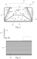
- Figur 2
- eine Schnittdarstellung der Leuchte senkrecht zur Längsachse, wobei die für die Lichtabgabe verantwortlichen Komponenten erkennbar sind;
- Figur 2a
- eine vergrößerte Ansicht eines Teils einer Seitenwand der Leuchtenabdeckung;
- Figur 3
- eine seitliche Ansicht des für die erfindungsgemäße Lichtabgabe vorgesehenen flächigen Bereichs der Abdeckung;
- Figur 4
- verschiedene Varianten von Mustern zur Bedruckung des zusätzlichen Lichtbeeinflussungselements und
- Figur 5
- das sich aus der Überlagerung der Strukturierung der Abdeckung mit dem Muster ergebende Erscheinungsbild der Leuchte.
- Die erfindungsgemäßen Maßnahmen zur Erzeugung des speziellen lichttechnischen Effekts sollen nachfolgend anhand eines Ausführungsbeispiels einer Leuchte beschrieben werden, welche in ihrem Aufbau grundsätzlich der aus dem Stand der Technik bekannten, oben beschriebenen Leuchte entspricht. Allerdings ist darauf hinzuweisen, dass die erfindungsgemäße Lichtabgabe auch bei anders gestalteten Leuchten zum Einsatz kommen könnte.
- Die in den Figuren allgemein mit dem Bezugszeichen 100 versehene Leuchte ist länglich ausgeführt und im dargestellten Ausführungsbeispiel als Pendelleuchte ausgebildet. In vergleichbarer Weise wäre allerdings auch ein Deckenanbau der Leuchte 100 denkbar.
- Zentrales haltendes Element der Leuchte 100 ist ein sich in Längsrichtung erstreckender Träger 10, welcher der Halterung sämtlicher weiterer Komponenten der Leuchte 100 dient und an dem auch entsprechende Aufhängungselemente 110 befestigt sind. Insbesondere dient der Träger 100 allerdings der Halterung der für die Lichterzeugung erforderlichen Leuchtmittel sowie ggf. erforderlicher Betriebsmittel, die eine der Leuchte 100 zugeführte Versorgungsspannung in eine zum Betreiben der Leuchtmittel geeignete Spannung umsetzen. Dies gilt insbesondere für den bevorzugten Fall, dass als Leuchtmittel sich in Längsrichtung erstreckende LED-Platinen zum Einsatz kommen, welche eine Vielzahl von hintereinander angeordneten LEDs aufweisen.
- Weiterhin ist an dem Träger 10 eine Abdeckung 20 befestigt, welche im Querschnitt die insbesondere in
Figur 2 erkennbare Form aufweist. Es handelt sich also um eine in etwa U-artige Querschnittsform, die eine Bodenfläche 21 sowie zwei Seitenwände 25 aufweist. An ihrer dem Träger 10 zugewandten Oberseite ist die Abdeckung 20 allerdings zusätzlich mit nach innen gerichteten Wandbereichen 23 ausgeführt, die sich bis zum Träger 10 hin erstrecken. Insgesamt umschließt somit die Abdeckung 20 einen länglichen rechteckigen Aufnahmeraum, in dem die für die Lichterzeugung und Lichtabgabe verantwortlichen Komponenten der Leuchte 100 angeordnet sind. - An den Stirnseiten ist die Leuchte 100 jeweils durch entsprechende Stirnelemente 15 abgeschlossen, welche auf die offenen Endbereiche der Abdeckung 20 aufgesteckt und hier mit dieser verbunden werden. Hierdurch wird der Raum im Inneren der Abdeckung 20 vollständig umschlossen, sodass die Leuchte 100 ggf. auch die Anforderungen entsprechender sog. Schutzklassen erfüllen kann, also gegen das Eindringen von Staub, Schmutz und/oder Feuchtigkeit entsprechend geschützt ist.
- Die Abdeckung 20 besteht insgesamt aus einem lichtdurchlässigen, vorzugsweise klaren Material. Dementsprechend ist vorgesehen, dass über sämtliche Flächen hinweg eine Lichtabgabe erfolgt, sodass - bzgl. der Längsachse der Leuchte 100 - von einer Lichtabgabe über 360° hinweg gesprochen werden kann.
- Die Hauptlichtabgabe soll hierbei über die Bodenfläche 21 erfolgen, sodass eine direkte Lichtabgabe zur Unterseite hin vorliegt, die bspw. zur Beleuchtung von Arbeitsflächen bzw. Arbeitsplätzen oder von unterhalb der Leuchte 100 befindlichen Objekten genutzt wird. Die beiden oberen Wandbereiche 23 der Abdeckung 20 hingegen dienen dazu, einen geringen Anteil des Lichts nach oben bspw. in Richtung einer Decke eines Raums, in dem die Leuchte 100 montiert ist, abzugeben. Hierdurch kann der Deckenbereich oberhalb der Leuchte 100 leicht aufgehellt werden. Auch dieser indirekt in den Raum abgegebene Anteil des Lichts wird über Reflektionen an Raumbegrenzungsflächen auf die Arbeitsfläche gelenkt und ist als Ergänzung zu den weiteren Lichtanteilen maßgeblich für eine angenehme Raumatmosphäre verantwortlich.
- Ggf. kann an der dem Innenraum zugewandten Oberfläche der Wandabschnitte 23 der Abdeckung 20 eine Strukturierung oder dergleichen vorgesehen sein, um eine bessere Verteilung des nach oben hin abgegebenen Lichts zu bewirken. Auch für die Lichtabgabe zur Unterseite hin sind im Folgenden näher beschriebene Maßnahmen vorgesehen, um das Licht in gewünschter Weise zu beeinflussen.
- Zunächst ist hierbei innerhalb des von der Abdeckung 20 umschlossenen Raums ein optisches Element 40 angeordnet, welches z.B. aus einem lichtstreuenden Material gebildet ist und welches dazu dient, das Licht der in
Figur 2 schematisch dargestellten Leuchtmittel 18, 19 vor einer Abgabe insbesondere über die Bodenseite 21 der Abdeckung 20 zu beeinflussen. Das lichtstreuende Element 40 weist hierbei einen etwa H-artigen Querschnitt mit einer unterhalb der Leuchtmittel 18, 19 angeordneten Horizontalfläche 41 auf, von der sich geneigt zwei Arme 42 schräg nach unten im Wesentlichen zu den unteren Ecken der Abdeckung 20 hin erstrecken. Vorzugsweise ist das Element 40 einstückiger Bestandteil der im Strangpressverfahren hergestellten Abdeckung 20 und somit an den unteren Enden mit dieser verbunden, wieFigur 2 zeigt. Während allerdings die verschiedenen seitlichen Wände 21, 23, 25 der Abdeckung aus einem klaren Material bestehen, ist das Lichtbeeinflussungselement 40 durchgängig vorzugsweise aus einem lichtstreuenden Material ausgebildet. Weiterhin sind an den Seitenbereichen der Horizontalfläche 41 jeweils sich nach oben erstreckende Stege 43 vorgesehen. - Das Lichtbeeinflussungselement 40 dient dann dazu, die einzelnen LEDs 19 als individuelle Lichtpunkte aufzulösen. Dies ist insbesondere für die Lichtabgabe über die Bodenfläche 21 der Abdeckung 20 wichtig, da hier eine möglichst gleichmäßige Ausleuchtung des zu beleuchtenden Bereichs erzielt werden soll und ferner die LEDs nicht mehr als einzelne Leuchtmittel wahrnehmbar sein sollen.
- Ferner ist im Bereich der klaren Bodenfläche 21 vorzugsweise ein weiteres plattenförmiges Element 45 angeordnet, welches an einer Flachseite eine Mikropyramidenoptik aufweist. Derartige Mikropyramidenoptiken sind an sich bereits bekannt und werden in der Beleuchtungstechnologie dazu verwendet, das flächig abgegebene Licht derart zu beeinflussen, dass es die Leuchte über einen vorgegebenen Winkelbereich verlässt, der insbesondere derart gewählt ist, dass keine störenden Reflexionen oder andere Blendeffekte auftreten. Gleichzeitig trägt auch diese Mikropyramidenoptik nochmals zusätzlich dazu bei, dass die einzelnen LEDs 19 nicht als individuelle Lichtquellen wahrgenommen werden können.
- Im darstellten Fall ist die Mikropyramidenoptik wie bereits erwähnt Bestandteil eines separaten plattenförmigen Elements 45, welches im Bodenbereich in die Abdeckung 20 eingelegt bzw. eingeschoben ist, wobei auf diesem Element 45 aufliegend ggf. noch eine nicht dargestellte diffus streuende Folie vorgesehen sein kann. Ggf. könnte jedoch die Mikropyramidenoptik auch bereits in die Bodenfläche 21 der Abdeckung 20 integriert sein. Somit wird bei der dargestellten Leuchte 100 das direkt zur Unterseite hin abgegebene Licht aufeinanderfolgend durch mehrere Komponenten beeinflusst: H-förmiger Diffusor 40 (diffus streuend) - evtl. MPO-Folie (diffus streuend) - Platte 45 mit Mikropyramidenstruktur - klare Bodenfläche 21 der Abdeckung 20.
- Die vorliegende Erfindung befasst sich insbesondere mit der Lichtabgabe über die Seitenwände 25 der Abdeckung 20, die zu einem optimierten Erscheinungsbild der Leuchte 100 führen soll. Hier steht weniger der Aspekt der Beleuchtung eines bestimmten Bereichs außerhalb der Leuchte 100 im Vordergrund, sondern es ist gewünscht, dass ein eher geringer Teil des Lichts der Leuchtmittel 18 seitlich derart abgegeben wird, dass die Leuchte 100 für einen Beobachter in besonders ansprechender Weise erscheint.
- Hierzu ist vorgesehen, dass die Seitenwände 25 der Abdeckung 20 vorzugsweise aus einem klaren Material bestehen, allerdings eine Strukturierung aufweisen, die in
Figur 2 erkennbar und inFigur 2a im Schnitt vergrößert dargestellt ist. Diese Fresnel-artige Strukturierung 26 besteht aus dem Innenraum der Leuchte 100 zugewandten Erhebungen, die Prismen-artig ausgeführt sind. Sie weisen im dargestellten Ausführungsbeispiel insbesondere eine dreieckige, besonders bevorzugt sägezahnartige Querschnittsform auf, um durch die entsprechenden Seitenwände 25 hindurchtretende Lichtstrahlen entsprechend zu beeinflussen. - Wie die seitliche Ansicht gemäß
Figur 3 zeigt, ist hierbei vorzugsweise vorgesehen, dass die Strukturierung 26 in Längsrichtung gesehen translationsinvariant ist, sich also in Längsrichtung der Leuchte 100 nicht verändert. Grundsätzlich wäre es allerdings auch denkbar, anders gestaltete Strukturierungen, insbesondere matrixartig ausgebildete Prismen- oder Linsenstrukturen zu verwenden. - Strukturierungen, wie sie soeben beschrieben wurden, sind an sich bereits bekannt, um die Lichtabgabe einer Leuchte positiv zu beeinflussen. Gemäß der vorliegenden Erfindung ist nunmehr allerdings vorgesehen, dass das Licht er Leuchtmittel, bevor es die Abdeckung 20 über die Seitenwände 25 verlassen kann, zusätzlich durch zwei seitlich in dem Innenraum der Leuchte 100 angeordnete Lichtbeeinflussungselemente 30 beeinflusst wird. Es handelt sich hierbei wiederum um Elemente, die aus einem lichtdurchlässigen Material bestehen, allerdings zusätzlich mit einem Muster 35 versehen, insbesondere bedruckt sind, was nachfolgend noch näher erläutert wird.
- Erfindungsgemäß werden die Lichtbeeinflussungselemente 30 in Form von Folien zur Verfügung gestellt, welche dann wie in
Figur 2 gezeigt in die Abdeckung 20 der Leuchte 100 eingeklemmt werden. Hierzu weisen die Folien eine gewisse Stärke bzw. Dicke von z.B. etwa 0,5 mm auf, sodass das resultierende Lichtbeeinflussungselement 30 eine entsprechende Eigenstabilität aufweist, um das Einklemmen in der dargestellten Weise zu ermöglichen. Abhängig von den Abmessungen, insbesondere der Höhe des Lichtbeeinflussungselements 30 kann hierbei vorgesehen sein, dass sich dieses geradlinig von dem unteren Eckbereich der Abdeckung 20 schräg nach oben erstreckt, wie dies inFigur 2 mit den durchgezogenen Linien dargestellt wird. Allerdings kann auch vorgesehen sein, dass die Höhe des Lichtbeeinflussungselements 30 etwas größer gewählt wird, sodass die Folie gewölbt vorgespannt entweder konvex oder konkav in die Abdeckung 20 eingeklemmt wird. - Entscheidend ist, dass das zusätzliche Lichtbeeinflussungselement 30 einen gewissen Abstand von der Seitenwand 25 der Abdeckung 20 aufweist und wie bereits erwähnt mit einem Muster 35 versehen ist.
Figur 4 zeigt hierbei Beispiele verschiedener möglicher Muster 35, wobei diese Muster 35 wiederum entweder in Längsrichtung sich nicht verändern, zumindest jedoch periodisch bzw. sich wiederholend ausgeführt sind. In einer Richtung senkrecht hierzu, bei der Darstellung gemäßFigur 4 also von oben nach unten, kann hingegen durchaus eine Veränderung des Musters 35 vorgesehen sein, was insbesondere der Tatsache Rechnung trägt, dass die unteren Bereiche des Lichtbeeinflussungselements 30 weiter von den Lichtquellen 18 entfernt sind und hier ein etwas geringerer Anteil an Licht hindurchtreten wird. Insbesondere kann dementsprechend vorgesehen sein, dass die Größe bzw. Dichte der Strukturen des Musters 35 zur Unterseite hin abnimmt. - Licht, welches über die Seitenwände der Abdeckung 20 abgegeben wird, wird also einerseits durch das bedruckte Muster 35 des Lichtbeeinflussungselements 30 beeinflusst, andererseits durch die Strukturierung 26 der Seitenwände 25 der Abdeckung 20. Es ergibt sich in diesem Fall ein sog. Moiré-Effekt, also ein optischer Effekt, der durch die Überlagerung von regelmäßigen, kleineren Strukturen entsteht. In der Regel führt eine derartige Überlagerung dazu, dass sich für einen Beobachter das Erscheinungsbild eines größeren, groben Rasters ergibt, dessen Aussehen den Mustern aus Interferenzen ähnlich ist. Derartige Effekte treten bspw. in der Digitalfotographie auf. Während sie dort allerdings eher nicht erwünscht sind, führen sie im vorliegenden Fall dazu, dass sich für einen Beobachter ein Tiefeneffekt bei einer Beobachtung der Seitenwände 25 der Leuchte 100 ergibt, sodass ein besonderes Erscheinungsbild erzielt wird. In
Figur 5 ist angedeutet, inwiefern das ursprüngliche Muster 35 entsprechend der Darstellung inFigur 4 durch die Überlagerung mit der Strukturierung 26 der Seitenwand 25 beeinflusst wird. Bereits geringfügige Änderungen des Blinkwinkels führen dann allerdings dazu, dass die Überlagerung zu einem anderen Erscheinungsbild führt, was letztendlich den angestrebten Tiefeneffekt ergibt. - Das Zusammenwirken zwischen Strukturierung 26 und Bedruckungsmuster 35 ist dann besonders effizient, wenn beide Komponenten vergleichbare Größenverhältnisse aufweisen. Dies bedeutet, dass die kleinsten Komponenten des bedruckten Musters 35 in etwa vergleichbare Größen aufweisen wie die Fresnel-artigen Strukturen der Seitenwände 25. In einem bevorzugten Ausführungsbeispiel ist vorgesehen, dass diese sägezahnartigen Strukturen Abmessungen im Bereich von etwa 1,5mm aufweisen, wobei dann auch bei den in
Figur 4 gezeigten Mustern 35 die entsprechenden Einzelstrukturen in etwa in der gleichen Größenordnung gewählt sein sollten. - Ein Vorteil der erfindungsgemäßen Lösung besteht darin, dass das Bedrucken der optischen Elemente 30 mit den verschiedenen Mustern 35 in sehr einfacher aber dennoch präziser Weise durchgeführt werden kann. Letztendlich eröffnet dies die Möglichkeit, auch unterschiedliche Muster in einfacher Weise zur Verfügung stellen zu können. Hierbei ist vorzugsweise vorgesehen, dass die dunklen Bereiche des Musters nicht vollkommen lichtblockend ausgeführt sind, sondern ein Kontrast zwischen den Hell- und Dunkelstellen der Bedruckung vorliegt, der im Bereich von etwa 30 - 50% liegt. Es hat sich herausgestellt, dass hierdurch einerseits noch eine ausreichend hohe Lichtmenge über die Seitenwände 25 der Abdeckung 20 abgegeben werden kann, andererseits trotz allem der angesprochene Tiefeneffekt ausreichend wahrnehmbar realisiert werden kann.
- Letztendlich wird also durch die Erfindung eine Leuchte geschaffen, welche aufgrund äußerst ansprechender lichttechnischer Effekte zu einem positiven Erscheinungsbild führt. Ein Vorteil der Lösung besteht hierbei insbesondere darin, dass der Aufwand zum Erzielen der besonderen lichttechnischen Effekte verhältnismäßig gering ist.
Claims (13)
- Leuchte (100) mit Leuchtmitteln (18) sowie einer Abdeckung (20), welche zumindest einen flächigen Bereich (25) zur Lichtabgabe aufweist,wobei der flächige Bereich zur Lichtabgabe (25) aus einem transparenten Material besteht und an zumindest einer Seite mit einer Strukturierung (26) versehen ist,und wobei zwischen den Leuchtmitteln (18) und dem flächigen Bereich (25) zur Lichtabgabe ein durch eine Kunststofffolie gebildetes plattenförmiges Lichtbeeinflussungselement (30) angeordnet ist, welches mit einem Muster (35) bedruckt ist,dadurch gekennzeichnet,dass die das Lichtbeeinflussungselement (30) bildende Folie in die Abdeckung (20) eingeklemmt gelagert ist, derart, dass das Lichtbeeinflussungselement (30) einen Abstand von der Abdeckung (20) aufweist.
- Leuchte nach Anspruch 1,
dadurch gekennzeichnet,
dass die Strukturierung (26) an der Innenseite des flächigen Bereichs zur Lichtabgabe (25) ausgebildet ist. - Leuchte nach Anspruch 1 oder 2,
dadurch gekennzeichnet,
dass sich die Leuchte (100) entlang einer Längsachse erstreckt und die Strukturierung (26) in einer Richtung parallel zur Längsachse translationsinvariant ausgebildet ist. - Leuchte nach Anspruch 3,
dadurch gekennzeichnet,
dass die Strukturierung (26) fresnel-artig ausgebildet ist bzw. durch eine sich in Längsrichtung erstreckende Prismenstruktur gebildet ist. - Leuchte nach Anspruch 4,
dadurch gekennzeichnet,
dass die Prismenstruktur im Querschnitt dreieckige, insbesondere sägezahnartig ausgebildete Erhebungen (27) aufweist. - Leuchte nach einem der vorherigen Ansprüche sowie einem der Ansprüche 3 bis 5, dadurch gekennzeichnet,
dass das Muster (35) in Längsrichtung periodisch ausgebildet ist. - Leuchte nach Anspruch 6,
dadurch gekennzeichnet,
dass das Muster (35) in einer Richtung senkrecht zur Längsrichtung sich verändernd ausgebildet ist. - Leuchte nach einem der vorherigen Ansprüche,
dadurch gekennzeichnet,
dass die Abdeckung (20) U-förmig ausgebildet ist mit zwei Seitenwänden sowie einer die Seitenwand verbindenden Bodenfläche (21), wobei beide Seitenwände flächige Bereiche zur Lichtabgabe (25) bilden. - Leuchte nach Anspruch 8,
dadurch gekennzeichnet,
dass die Bodenfläche (21) der Abdeckung (20) ebenfalls lichtdurchlässig ausgebildet ist. - Leuchte nach Anspruch 9,
dadurch gekennzeichnet,
dass der Bodenfläche (21) ein lichtstreuendes Element (40) vorgeordnet ist. - Leuchte nach Anspruch 10,
dadurch gekennzeichnet,
dass das lichtstreuende Element eine parallel zur Bodenfläche (21) der Abdeckung angeordnete Wand (41) sowie zwei sich davon trapez-artig erstreckende Arme (42) aufweist. - Leuchte nach Anspruch 10 oder 11,
dadurch gekennzeichnet,
dass das lichtstreuende Element (40) einstückig mit der Abdeckung (20) verbunden ist. - Leuchte nach einem der Ansprüche 10 bis 12,
dadurch gekennzeichnet,
dass zwischen dem lichtstreuenden Element (40) und der Bodenfläche (21) der Abdeckung (20) ein weiteres optisches Element (45) angeordnet ist, welches eine Mikropyramidenstruktur aufweist.
Applications Claiming Priority (2)
| Application Number | Priority Date | Filing Date | Title |
|---|---|---|---|
| DE202019105265.1U DE202019105265U1 (de) | 2019-09-24 | 2019-09-24 | Leuchte mit Bereich zur flächigen Lichtabgabe |
| PCT/EP2020/070411 WO2021058167A1 (de) | 2019-09-24 | 2020-07-20 | Leuchte mit bereich zur flächigen lichtabgabe |
Publications (2)
| Publication Number | Publication Date |
|---|---|
| EP4034807A1 EP4034807A1 (de) | 2022-08-03 |
| EP4034807B1 true EP4034807B1 (de) | 2025-01-08 |
Family
ID=71784008
Family Applications (1)
| Application Number | Title | Priority Date | Filing Date |
|---|---|---|---|
| EP20745124.6A Active EP4034807B1 (de) | 2019-09-24 | 2020-07-20 | Leuchte mit bereich zur flächigen lichtabgabe |
Country Status (6)
| Country | Link |
|---|---|
| US (1) | US20220325856A1 (de) |
| EP (1) | EP4034807B1 (de) |
| CN (1) | CN114364915A (de) |
| AT (1) | AT18309U1 (de) |
| DE (1) | DE202019105265U1 (de) |
| WO (1) | WO2021058167A1 (de) |
Families Citing this family (2)
| Publication number | Priority date | Publication date | Assignee | Title |
|---|---|---|---|---|
| US11852333B1 (en) * | 2022-10-25 | 2023-12-26 | Abl Ip Holding Llc | Light fixture with glare reduction panels |
| DE102024200785A1 (de) * | 2024-01-29 | 2025-07-31 | Stellantis Auto Sas | Optisches Element einer Leuchtvorrichtung für einen Innenraum eines Fahrzeugs sowie die Leuchtvorrichtung aufweisendes Fahrzeug |
Family Cites Families (36)
| Publication number | Priority date | Publication date | Assignee | Title |
|---|---|---|---|---|
| US1472050A (en) * | 1921-09-17 | 1923-10-30 | Augustus D Curtis | Lighting fixture |
| US2474308A (en) * | 1946-11-29 | 1949-06-28 | Holophane Co Inc | Surface attached lighting equipment |
| US4186433A (en) * | 1978-02-21 | 1980-01-29 | General Electric Company | Luminaire |
| JPS63176228U (de) * | 1987-05-07 | 1988-11-15 | ||
| US4768140A (en) * | 1987-05-19 | 1988-08-30 | Roman Szpur | Indoor light fixture for high intensity lamp |
| DE4039290A1 (de) * | 1990-12-08 | 1992-06-11 | Minnesota Mining & Mfg | Leuchte |
| US5258895A (en) * | 1992-03-09 | 1993-11-02 | Bosse Thomas W | Moire light assembly |
| DE29923835U1 (de) * | 1999-04-07 | 2001-04-05 | Zumtobel Staff Gmbh | Beleuchtungsanordnung zur Anbringung an der Decke oder einer Wand eines Raumes |
| CA2430076C (en) * | 2000-11-29 | 2009-05-26 | Zumtobel Staff Gmbh | Light with a transparent panel |
| US6898012B2 (en) * | 2002-05-16 | 2005-05-24 | Eastman Kodak Company | Light reflector with variable diffuse light reflection |
| US7866871B2 (en) * | 2006-01-13 | 2011-01-11 | Avery Dennison Corporation | Light enhancing structures with a plurality of arrays of elongate features |
| US7883226B2 (en) * | 2007-03-05 | 2011-02-08 | Intematix Corporation | LED signal lamp |
| US8047673B2 (en) * | 2007-04-10 | 2011-11-01 | Philips Electronics Ltd | Light control device exhibiting batwing luminous intensity distributions in upper and lower hemispheres |
| DE202007011211U1 (de) * | 2007-08-10 | 2008-12-24 | Zumtobel Lighting Gmbh | Leuchte |
| DE202007011212U1 (de) * | 2007-08-10 | 2008-12-24 | Zumtobel Lighting Gmbh | Leuchte mit Raster zur Lichtabgabe |
| US8534877B1 (en) * | 2008-04-03 | 2013-09-17 | Stingray Energy Systems LLC | Luminaire optical systems |
| AT11163U1 (de) * | 2008-10-09 | 2010-05-15 | Zumtobel Lighting Gmbh | Leuchte |
| JP2011084942A (ja) * | 2009-10-15 | 2011-04-28 | Itoki Corp | 透過視認性制御パネルを用いたオフィス家具 |
| KR100982727B1 (ko) * | 2010-01-15 | 2010-09-17 | 엄용식 | Led 조명기구 |
| FR2970011B1 (fr) * | 2010-12-30 | 2013-01-11 | Normalu | Dispositif lumineux destine a etre integre a une fausse paroi et permettant d'obtenir un effet esthetique en trois dimensions |
| DE102011051038A1 (de) * | 2011-06-14 | 2012-12-20 | Selux Aktiengesellschaft | LED Beleuchtungsanordnung |
| KR101279486B1 (ko) * | 2011-08-17 | 2013-06-27 | 엘지이노텍 주식회사 | 조명 부재 및 이를 이용한 조명기기 |
| AT514917B1 (de) * | 2013-11-22 | 2015-05-15 | Neulicht Lighting Solutions Gmbh | LED-Leuchte |
| JP2015149246A (ja) * | 2014-02-07 | 2015-08-20 | パナソニックIpマネジメント株式会社 | 照明用光源及び照明装置 |
| JP6143974B1 (ja) * | 2014-05-09 | 2017-06-07 | フィリップス ライティング ホールディング ビー ヴィ | 線状照明デバイス及び当該線状照明デバイスを製造する方法 |
| US20150360606A1 (en) * | 2014-06-12 | 2015-12-17 | Nthdegree Technologies Worldwide Inc. | Thin flexible led light sheet applications |
| CN105674112A (zh) * | 2014-12-05 | 2016-06-15 | 嘉兴山蒲照明电器有限公司 | Led直管灯 |
| US10101002B2 (en) * | 2015-11-09 | 2018-10-16 | Apple Inc. | Light fixture with fabric layer having printed dots |
| DE202016002197U1 (de) * | 2016-04-01 | 2016-06-06 | Osram Gmbh | Direktstrahlende LED-Leuchte mit Entblendungsoptik |
| US10082275B2 (en) * | 2016-04-21 | 2018-09-25 | Hubbell Incorporated | Wall wash light fixture |
| JP6765055B2 (ja) * | 2016-08-19 | 2020-10-07 | パナソニックIpマネジメント株式会社 | 照明器具 |
| CN106439545B (zh) * | 2016-11-22 | 2022-11-15 | 东莞泛美光电有限公司 | 替换式led灯具 |
| US20180245754A1 (en) * | 2017-02-27 | 2018-08-30 | Elemental LED, Inc. | Linear LED Lighting with Built-In Light Modifiers |
| DE102017125245A1 (de) * | 2017-10-27 | 2019-05-02 | Siteco Beleuchtungstechnik Gmbh | Abdeckung für ein Leuchtmodul, Leuchtmodul und Leuchte |
| JP2019184332A (ja) * | 2018-04-05 | 2019-10-24 | 日本精機株式会社 | 計器装置 |
| EP3626425B1 (de) * | 2018-09-20 | 2023-01-18 | Zumtobel Lighting GmbH | Lampenkomponente zur bildung einer lampe mit grossem abstrahlwinkel, lampe und verfahren zur herstellung solch einer lampenkomponente |
-
2019
- 2019-09-24 DE DE202019105265.1U patent/DE202019105265U1/de active Active
- 2019-12-10 AT ATGM50222/2019U patent/AT18309U1/de unknown
-
2020
- 2020-07-20 US US17/639,974 patent/US20220325856A1/en not_active Abandoned
- 2020-07-20 EP EP20745124.6A patent/EP4034807B1/de active Active
- 2020-07-20 CN CN202080062586.8A patent/CN114364915A/zh active Pending
- 2020-07-20 WO PCT/EP2020/070411 patent/WO2021058167A1/de not_active Ceased
Also Published As
| Publication number | Publication date |
|---|---|
| DE202019105265U1 (de) | 2021-01-04 |
| CN114364915A (zh) | 2022-04-15 |
| WO2021058167A1 (de) | 2021-04-01 |
| EP4034807A1 (de) | 2022-08-03 |
| US20220325856A1 (en) | 2022-10-13 |
| AT18309U1 (de) | 2024-09-15 |
Similar Documents
| Publication | Publication Date | Title |
|---|---|---|
| EP1688662B1 (de) | Leuchte | |
| EP4034807B1 (de) | Leuchte mit bereich zur flächigen lichtabgabe | |
| AT15359U1 (de) | Längliche LED-Leuchte mit optischem Element | |
| EP2796769A2 (de) | LED-Leuchte mit einer Lichtleiter-Anordnung | |
| EP2994693B1 (de) | Abdeckungselement für flächenleuchte | |
| EP2166276B1 (de) | Anordnung zur Bildung einer länglichen Lichtquelle | |
| EP3631554B1 (de) | Optische anordnung für eine lichtquelle | |
| AT16319U1 (de) | Optisches System sowie Anordnung zur Lichtabgabe | |
| EP2518389B2 (de) | Anordnung zur Lichtabgabe mit einem länglichen optischen Element | |
| CH715292B1 (de) | Optikrohling, Verfahren und Linearleuchte. | |
| DE102017203200A1 (de) | Leuchtenwanne zum Bilden eines Leuchtengehäuses | |
| EP3557124B1 (de) | Flache led-leuchte | |
| EP2176583B1 (de) | Leuchte mit raster zur lichtabgabe | |
| EP3112747B1 (de) | Optisches element zur beeinflussung der lichtabgabe einer länglichen lichtquelle | |
| EP1467141A2 (de) | Leuchte mit geschlossener Lichtabstrahlfläche | |
| EP3882517B1 (de) | Led-leuchte | |
| EP2796779A1 (de) | Leuchte mit optischem System zur Lichtabgabe über eine längliche Lichtaustrittsöffnung | |
| EP4168711B1 (de) | Anordnung zur lichtabgabe und leuchte | |
| DE102018119606A1 (de) | Optisches Element für eine Leuchte, insbesondere Büroleuchte, sowie Leuchte | |
| EP2107297B1 (de) | Leuchte, insbesondere Raumleuchte | |
| EP2355076A2 (de) | Leuchte mit biegsamem Lichtbeeinflussungsmittel | |
| DE10133360A1 (de) | Downlight mit Seitenreflektor | |
| EP2994690B1 (de) | Leuchte mit gehäuse mit mehreren lichtabstrahlöffnungen | |
| DE202014102021U1 (de) | Optisches Element für eine Lichtquelle einer Leuchte, sowie Leuchte | |
| DE202013105863U1 (de) | Anordnung zum Entblenden der Lichtabgabe |
Legal Events
| Date | Code | Title | Description |
|---|---|---|---|
| STAA | Information on the status of an ep patent application or granted ep patent |
Free format text: STATUS: UNKNOWN |
|
| STAA | Information on the status of an ep patent application or granted ep patent |
Free format text: STATUS: THE INTERNATIONAL PUBLICATION HAS BEEN MADE |
|
| PUAI | Public reference made under article 153(3) epc to a published international application that has entered the european phase |
Free format text: ORIGINAL CODE: 0009012 |
|
| STAA | Information on the status of an ep patent application or granted ep patent |
Free format text: STATUS: REQUEST FOR EXAMINATION WAS MADE |
|
| 17P | Request for examination filed |
Effective date: 20220228 |
|
| AK | Designated contracting states |
Kind code of ref document: A1 Designated state(s): AL AT BE BG CH CY CZ DE DK EE ES FI FR GB GR HR HU IE IS IT LI LT LU LV MC MK MT NL NO PL PT RO RS SE SI SK SM TR |
|
| DAV | Request for validation of the european patent (deleted) | ||
| DAX | Request for extension of the european patent (deleted) | ||
| GRAP | Despatch of communication of intention to grant a patent |
Free format text: ORIGINAL CODE: EPIDOSNIGR1 |
|
| STAA | Information on the status of an ep patent application or granted ep patent |
Free format text: STATUS: GRANT OF PATENT IS INTENDED |
|
| INTG | Intention to grant announced |
Effective date: 20241002 |
|
| GRAS | Grant fee paid |
Free format text: ORIGINAL CODE: EPIDOSNIGR3 |
|
| GRAA | (expected) grant |
Free format text: ORIGINAL CODE: 0009210 |
|
| STAA | Information on the status of an ep patent application or granted ep patent |
Free format text: STATUS: THE PATENT HAS BEEN GRANTED |
|
| AK | Designated contracting states |
Kind code of ref document: B1 Designated state(s): AL AT BE BG CH CY CZ DE DK EE ES FI FR GB GR HR HU IE IS IT LI LT LU LV MC MK MT NL NO PL PT RO RS SE SI SK SM TR |
|
| P01 | Opt-out of the competence of the unified patent court (upc) registered |
Free format text: CASE NUMBER: APP_63542/2024 Effective date: 20241129 |
|
| REG | Reference to a national code |
Ref country code: GB Ref legal event code: FG4D Free format text: NOT ENGLISH |
|
| REG | Reference to a national code |
Ref country code: CH Ref legal event code: EP |
|
| REG | Reference to a national code |
Ref country code: DE Ref legal event code: R096 Ref document number: 502020010161 Country of ref document: DE |
|
| REG | Reference to a national code |
Ref country code: IE Ref legal event code: FG4D Free format text: LANGUAGE OF EP DOCUMENT: GERMAN |
|
| REG | Reference to a national code |
Ref country code: LT Ref legal event code: MG9D |
|
| REG | Reference to a national code |
Ref country code: NL Ref legal event code: MP Effective date: 20250108 |
|
| PG25 | Lapsed in a contracting state [announced via postgrant information from national office to epo] |
Ref country code: NL Free format text: LAPSE BECAUSE OF FAILURE TO SUBMIT A TRANSLATION OF THE DESCRIPTION OR TO PAY THE FEE WITHIN THE PRESCRIBED TIME-LIMIT Effective date: 20250108 |
|
| PG25 | Lapsed in a contracting state [announced via postgrant information from national office to epo] |
Ref country code: RS Free format text: LAPSE BECAUSE OF FAILURE TO SUBMIT A TRANSLATION OF THE DESCRIPTION OR TO PAY THE FEE WITHIN THE PRESCRIBED TIME-LIMIT Effective date: 20250408 |
|
| PG25 | Lapsed in a contracting state [announced via postgrant information from national office to epo] |
Ref country code: FI Free format text: LAPSE BECAUSE OF FAILURE TO SUBMIT A TRANSLATION OF THE DESCRIPTION OR TO PAY THE FEE WITHIN THE PRESCRIBED TIME-LIMIT Effective date: 20250108 |
|
| PG25 | Lapsed in a contracting state [announced via postgrant information from national office to epo] |
Ref country code: PL Free format text: LAPSE BECAUSE OF FAILURE TO SUBMIT A TRANSLATION OF THE DESCRIPTION OR TO PAY THE FEE WITHIN THE PRESCRIBED TIME-LIMIT Effective date: 20250108 |
|
| PG25 | Lapsed in a contracting state [announced via postgrant information from national office to epo] |
Ref country code: ES Free format text: LAPSE BECAUSE OF FAILURE TO SUBMIT A TRANSLATION OF THE DESCRIPTION OR TO PAY THE FEE WITHIN THE PRESCRIBED TIME-LIMIT Effective date: 20250108 |
|
| PG25 | Lapsed in a contracting state [announced via postgrant information from national office to epo] |
Ref country code: NO Free format text: LAPSE BECAUSE OF FAILURE TO SUBMIT A TRANSLATION OF THE DESCRIPTION OR TO PAY THE FEE WITHIN THE PRESCRIBED TIME-LIMIT Effective date: 20250408 Ref country code: IS Free format text: LAPSE BECAUSE OF FAILURE TO SUBMIT A TRANSLATION OF THE DESCRIPTION OR TO PAY THE FEE WITHIN THE PRESCRIBED TIME-LIMIT Effective date: 20250508 |
|
| PG25 | Lapsed in a contracting state [announced via postgrant information from national office to epo] |
Ref country code: HR Free format text: LAPSE BECAUSE OF FAILURE TO SUBMIT A TRANSLATION OF THE DESCRIPTION OR TO PAY THE FEE WITHIN THE PRESCRIBED TIME-LIMIT Effective date: 20250108 |
|
| PG25 | Lapsed in a contracting state [announced via postgrant information from national office to epo] |
Ref country code: PT Free format text: LAPSE BECAUSE OF FAILURE TO SUBMIT A TRANSLATION OF THE DESCRIPTION OR TO PAY THE FEE WITHIN THE PRESCRIBED TIME-LIMIT Effective date: 20250508 Ref country code: LV Free format text: LAPSE BECAUSE OF FAILURE TO SUBMIT A TRANSLATION OF THE DESCRIPTION OR TO PAY THE FEE WITHIN THE PRESCRIBED TIME-LIMIT Effective date: 20250108 |
|
| PG25 | Lapsed in a contracting state [announced via postgrant information from national office to epo] |
Ref country code: BG Free format text: LAPSE BECAUSE OF FAILURE TO SUBMIT A TRANSLATION OF THE DESCRIPTION OR TO PAY THE FEE WITHIN THE PRESCRIBED TIME-LIMIT Effective date: 20250108 Ref country code: GR Free format text: LAPSE BECAUSE OF FAILURE TO SUBMIT A TRANSLATION OF THE DESCRIPTION OR TO PAY THE FEE WITHIN THE PRESCRIBED TIME-LIMIT Effective date: 20250409 |
|
| PG25 | Lapsed in a contracting state [announced via postgrant information from national office to epo] |
Ref country code: SE Free format text: LAPSE BECAUSE OF FAILURE TO SUBMIT A TRANSLATION OF THE DESCRIPTION OR TO PAY THE FEE WITHIN THE PRESCRIBED TIME-LIMIT Effective date: 20250108 |
|
| PG25 | Lapsed in a contracting state [announced via postgrant information from national office to epo] |
Ref country code: SM Free format text: LAPSE BECAUSE OF FAILURE TO SUBMIT A TRANSLATION OF THE DESCRIPTION OR TO PAY THE FEE WITHIN THE PRESCRIBED TIME-LIMIT Effective date: 20250108 |
|
| REG | Reference to a national code |
Ref country code: DE Ref legal event code: R097 Ref document number: 502020010161 Country of ref document: DE |
|
| PG25 | Lapsed in a contracting state [announced via postgrant information from national office to epo] |
Ref country code: DK Free format text: LAPSE BECAUSE OF FAILURE TO SUBMIT A TRANSLATION OF THE DESCRIPTION OR TO PAY THE FEE WITHIN THE PRESCRIBED TIME-LIMIT Effective date: 20250108 |
|
| PGFP | Annual fee paid to national office [announced via postgrant information from national office to epo] |
Ref country code: DE Payment date: 20250728 Year of fee payment: 6 |
|
| PGFP | Annual fee paid to national office [announced via postgrant information from national office to epo] |
Ref country code: GB Payment date: 20250722 Year of fee payment: 6 |
|
| PGFP | Annual fee paid to national office [announced via postgrant information from national office to epo] |
Ref country code: AT Payment date: 20250718 Year of fee payment: 6 Ref country code: FR Payment date: 20250725 Year of fee payment: 6 |
|
| PGFP | Annual fee paid to national office [announced via postgrant information from national office to epo] |
Ref country code: CH Payment date: 20250801 Year of fee payment: 6 |
|
| PG25 | Lapsed in a contracting state [announced via postgrant information from national office to epo] |
Ref country code: CZ Free format text: LAPSE BECAUSE OF FAILURE TO SUBMIT A TRANSLATION OF THE DESCRIPTION OR TO PAY THE FEE WITHIN THE PRESCRIBED TIME-LIMIT Effective date: 20250108 Ref country code: EE Free format text: LAPSE BECAUSE OF FAILURE TO SUBMIT A TRANSLATION OF THE DESCRIPTION OR TO PAY THE FEE WITHIN THE PRESCRIBED TIME-LIMIT Effective date: 20250108 |
|
| PG25 | Lapsed in a contracting state [announced via postgrant information from national office to epo] |
Ref country code: RO Free format text: LAPSE BECAUSE OF FAILURE TO SUBMIT A TRANSLATION OF THE DESCRIPTION OR TO PAY THE FEE WITHIN THE PRESCRIBED TIME-LIMIT Effective date: 20250108 |
|
| PG25 | Lapsed in a contracting state [announced via postgrant information from national office to epo] |
Ref country code: SK Free format text: LAPSE BECAUSE OF FAILURE TO SUBMIT A TRANSLATION OF THE DESCRIPTION OR TO PAY THE FEE WITHIN THE PRESCRIBED TIME-LIMIT Effective date: 20250108 |
|
| PLBE | No opposition filed within time limit |
Free format text: ORIGINAL CODE: 0009261 |
|
| STAA | Information on the status of an ep patent application or granted ep patent |
Free format text: STATUS: NO OPPOSITION FILED WITHIN TIME LIMIT |
|
| 26N | No opposition filed |
Effective date: 20251009 |
|
| PG25 | Lapsed in a contracting state [announced via postgrant information from national office to epo] |
Ref country code: IT Free format text: LAPSE BECAUSE OF FAILURE TO SUBMIT A TRANSLATION OF THE DESCRIPTION OR TO PAY THE FEE WITHIN THE PRESCRIBED TIME-LIMIT Effective date: 20250108 |
|
| PG25 | Lapsed in a contracting state [announced via postgrant information from national office to epo] |
Ref country code: LU Free format text: LAPSE BECAUSE OF NON-PAYMENT OF DUE FEES Effective date: 20250720 |
|
| REG | Reference to a national code |
Ref country code: BE Ref legal event code: MM Effective date: 20250731 |
|
| PG25 | Lapsed in a contracting state [announced via postgrant information from national office to epo] |
Ref country code: BE Free format text: LAPSE BECAUSE OF NON-PAYMENT OF DUE FEES Effective date: 20250731 |