EP4034807B1 - Luminaire ayant une région pour émettre de la lumière sur une surface - Google Patents
Luminaire ayant une région pour émettre de la lumière sur une surface Download PDFInfo
- Publication number
- EP4034807B1 EP4034807B1 EP20745124.6A EP20745124A EP4034807B1 EP 4034807 B1 EP4034807 B1 EP 4034807B1 EP 20745124 A EP20745124 A EP 20745124A EP 4034807 B1 EP4034807 B1 EP 4034807B1
- Authority
- EP
- European Patent Office
- Prior art keywords
- light
- cover
- luminaire according
- luminaire
- lamp
- Prior art date
- Legal status (The legal status is an assumption and is not a legal conclusion. Google has not performed a legal analysis and makes no representation as to the accuracy of the status listed.)
- Active
Links
Images


Classifications
-
- F—MECHANICAL ENGINEERING; LIGHTING; HEATING; WEAPONS; BLASTING
- F21—LIGHTING
- F21S—NON-PORTABLE LIGHTING DEVICES; SYSTEMS THEREOF; VEHICLE LIGHTING DEVICES SPECIALLY ADAPTED FOR VEHICLE EXTERIORS
- F21S4/00—Lighting devices or systems using a string or strip of light sources
- F21S4/20—Lighting devices or systems using a string or strip of light sources with light sources held by or within elongate supports
- F21S4/28—Lighting devices or systems using a string or strip of light sources with light sources held by or within elongate supports rigid, e.g. LED bars
-
- F—MECHANICAL ENGINEERING; LIGHTING; HEATING; WEAPONS; BLASTING
- F21—LIGHTING
- F21V—FUNCTIONAL FEATURES OR DETAILS OF LIGHTING DEVICES OR SYSTEMS THEREOF; STRUCTURAL COMBINATIONS OF LIGHTING DEVICES WITH OTHER ARTICLES, NOT OTHERWISE PROVIDED FOR
- F21V13/00—Producing particular characteristics or distribution of the light emitted by means of a combination of elements specified in two or more of main groups F21V1/00 - F21V11/00
-
- F—MECHANICAL ENGINEERING; LIGHTING; HEATING; WEAPONS; BLASTING
- F21—LIGHTING
- F21S—NON-PORTABLE LIGHTING DEVICES; SYSTEMS THEREOF; VEHICLE LIGHTING DEVICES SPECIALLY ADAPTED FOR VEHICLE EXTERIORS
- F21S8/00—Lighting devices intended for fixed installation
- F21S8/04—Lighting devices intended for fixed installation intended only for mounting on a ceiling or the like overhead structures
-
- F—MECHANICAL ENGINEERING; LIGHTING; HEATING; WEAPONS; BLASTING
- F21—LIGHTING
- F21V—FUNCTIONAL FEATURES OR DETAILS OF LIGHTING DEVICES OR SYSTEMS THEREOF; STRUCTURAL COMBINATIONS OF LIGHTING DEVICES WITH OTHER ARTICLES, NOT OTHERWISE PROVIDED FOR
- F21V11/00—Screens not covered by groups F21V1/00, F21V3/00, F21V7/00 or F21V9/00
-
- F—MECHANICAL ENGINEERING; LIGHTING; HEATING; WEAPONS; BLASTING
- F21—LIGHTING
- F21V—FUNCTIONAL FEATURES OR DETAILS OF LIGHTING DEVICES OR SYSTEMS THEREOF; STRUCTURAL COMBINATIONS OF LIGHTING DEVICES WITH OTHER ARTICLES, NOT OTHERWISE PROVIDED FOR
- F21V17/00—Fastening of component parts of lighting devices, e.g. shades, globes, refractors, reflectors, filters, screens, grids or protective cages
- F21V17/10—Fastening of component parts of lighting devices, e.g. shades, globes, refractors, reflectors, filters, screens, grids or protective cages characterised by specific fastening means or way of fastening
- F21V17/16—Fastening of component parts of lighting devices, e.g. shades, globes, refractors, reflectors, filters, screens, grids or protective cages characterised by specific fastening means or way of fastening by deformation of parts; Snap action mounting
- F21V17/162—Fastening of component parts of lighting devices, e.g. shades, globes, refractors, reflectors, filters, screens, grids or protective cages characterised by specific fastening means or way of fastening by deformation of parts; Snap action mounting the parts being subjected to traction or compression, e.g. coil springs
-
- F—MECHANICAL ENGINEERING; LIGHTING; HEATING; WEAPONS; BLASTING
- F21—LIGHTING
- F21V—FUNCTIONAL FEATURES OR DETAILS OF LIGHTING DEVICES OR SYSTEMS THEREOF; STRUCTURAL COMBINATIONS OF LIGHTING DEVICES WITH OTHER ARTICLES, NOT OTHERWISE PROVIDED FOR
- F21V3/00—Globes; Bowls; Cover glasses
- F21V3/04—Globes; Bowls; Cover glasses characterised by materials, surface treatments or coatings
- F21V3/049—Patterns or structured surfaces for diffusing light, e.g. frosted surfaces
-
- F—MECHANICAL ENGINEERING; LIGHTING; HEATING; WEAPONS; BLASTING
- F21—LIGHTING
- F21V—FUNCTIONAL FEATURES OR DETAILS OF LIGHTING DEVICES OR SYSTEMS THEREOF; STRUCTURAL COMBINATIONS OF LIGHTING DEVICES WITH OTHER ARTICLES, NOT OTHERWISE PROVIDED FOR
- F21V5/00—Refractors for light sources
- F21V5/002—Refractors for light sources using microoptical elements for redirecting or diffusing light
-
- F—MECHANICAL ENGINEERING; LIGHTING; HEATING; WEAPONS; BLASTING
- F21—LIGHTING
- F21V—FUNCTIONAL FEATURES OR DETAILS OF LIGHTING DEVICES OR SYSTEMS THEREOF; STRUCTURAL COMBINATIONS OF LIGHTING DEVICES WITH OTHER ARTICLES, NOT OTHERWISE PROVIDED FOR
- F21V5/00—Refractors for light sources
- F21V5/002—Refractors for light sources using microoptical elements for redirecting or diffusing light
- F21V5/005—Refractors for light sources using microoptical elements for redirecting or diffusing light using microprisms
-
- F—MECHANICAL ENGINEERING; LIGHTING; HEATING; WEAPONS; BLASTING
- F21—LIGHTING
- F21V—FUNCTIONAL FEATURES OR DETAILS OF LIGHTING DEVICES OR SYSTEMS THEREOF; STRUCTURAL COMBINATIONS OF LIGHTING DEVICES WITH OTHER ARTICLES, NOT OTHERWISE PROVIDED FOR
- F21V5/00—Refractors for light sources
- F21V5/008—Combination of two or more successive refractors along an optical axis
-
- F—MECHANICAL ENGINEERING; LIGHTING; HEATING; WEAPONS; BLASTING
- F21—LIGHTING
- F21V—FUNCTIONAL FEATURES OR DETAILS OF LIGHTING DEVICES OR SYSTEMS THEREOF; STRUCTURAL COMBINATIONS OF LIGHTING DEVICES WITH OTHER ARTICLES, NOT OTHERWISE PROVIDED FOR
- F21V5/00—Refractors for light sources
- F21V5/02—Refractors for light sources of prismatic shape
-
- G—PHYSICS
- G02—OPTICS
- G02B—OPTICAL ELEMENTS, SYSTEMS OR APPARATUS
- G02B5/00—Optical elements other than lenses
- G02B5/02—Diffusing elements; Afocal elements
- G02B5/0205—Diffusing elements; Afocal elements characterised by the diffusing properties
- G02B5/021—Diffusing elements; Afocal elements characterised by the diffusing properties the diffusion taking place at the element's surface, e.g. by means of surface roughening or microprismatic structures
-
- F—MECHANICAL ENGINEERING; LIGHTING; HEATING; WEAPONS; BLASTING
- F21—LIGHTING
- F21Y—INDEXING SCHEME ASSOCIATED WITH SUBCLASSES F21K, F21L, F21S and F21V, RELATING TO THE FORM OR THE KIND OF THE LIGHT SOURCES OR OF THE COLOUR OF THE LIGHT EMITTED
- F21Y2103/00—Elongate light sources, e.g. fluorescent tubes
-
- F—MECHANICAL ENGINEERING; LIGHTING; HEATING; WEAPONS; BLASTING
- F21—LIGHTING
- F21Y—INDEXING SCHEME ASSOCIATED WITH SUBCLASSES F21K, F21L, F21S and F21V, RELATING TO THE FORM OR THE KIND OF THE LIGHT SOURCES OR OF THE COLOUR OF THE LIGHT EMITTED
- F21Y2103/00—Elongate light sources, e.g. fluorescent tubes
- F21Y2103/10—Elongate light sources, e.g. fluorescent tubes comprising a linear array of point-like light-generating elements
-
- F—MECHANICAL ENGINEERING; LIGHTING; HEATING; WEAPONS; BLASTING
- F21—LIGHTING
- F21Y—INDEXING SCHEME ASSOCIATED WITH SUBCLASSES F21K, F21L, F21S and F21V, RELATING TO THE FORM OR THE KIND OF THE LIGHT SOURCES OR OF THE COLOUR OF THE LIGHT EMITTED
- F21Y2115/00—Light-generating elements of semiconductor light sources
- F21Y2115/10—Light-emitting diodes [LED]
Definitions
- the present invention relates to a luminaire according to the preamble of claim 1, which has lighting means, as well as a cover which forms at least one flat area for emitting light.
- the WO 02/44612 A2 describes a surface light, whereby the emitting surface can have light-scattering structures.
- an additional light equalization means can be arranged between the light sources and the emitting surface, which ensures additional scattering of the light and can be made of a film.
- Modern lights are often designed in such a way that they not only emit light in one way, but also emit another or additional light. While the primary light output serves to fulfil the task of the light in terms of its area of application, the additional light output is used to create a so-called accent light or to brighten an additional area in order to improve the overall appearance of the light itself and the illuminated area. The primary light output is then used, for example, to specifically illuminate a certain area below the light, e.g. for work purposes, or to specifically brighten areas below the light.
- a lamp which emits light in different ways in the sense of the above explanations is sold by the applicant under the name "ECOOS".
- ECOOS is a lamp which extends longitudinally and in which the light sources are enclosed by a roughly U-shaped cover.
- the underside of the cover is used to emit directed light to illuminate workstations or the like, while a smaller proportion of the light is also emitted via the side walls of the cover in order to improve the overall appearance of the lamp.
- Perforated aluminum reflectors are arranged in front of the side walls of the cover, the hole pattern of which allows some of the light to pass through, which is then emitted via the side walls of the cover.
- the aluminum reflectors reduce the proportion of light emitted via the side walls in such a way that there is no risk of glare. Furthermore, the fact that the reflectors are a certain distance from the side walls of the cover creates a so-called depth effect, so that the lamp as a whole appears to be a brilliant object. Despite everything, work spaces or communication areas can be efficiently illuminated with the help of this lamp, since a large part of the light generated by the lamps is emitted in the desired direction towards the underside.
- the lamp mentioned above is characterized by its particularly attractive light output and the resulting appearance.
- the use of the perforated aluminum reflectors responsible for the appearance is associated with certain disadvantages.
- the present invention is therefore based on the object of providing a novel possibility of achieving a light output for a luminaire that is comparable to that described above, but reducing the effort required for this.
- the light according to the invention is intended to at least partially produce a light output that produces the above-mentioned depth effect in an observer.
- the area of a light-emitting element intended for the corresponding light output consists of a transparent material and is provided with a structure on one side.
- a plate-shaped light-influencing element formed by a plastic film is arranged between the lighting means and the flat area for light output, which consists of a translucent material but is printed with a pattern.
- a lamp with lighting means and with a cover which forms at least one flat area for emitting light, wherein the flat area for emitting light consists of a transparent material and is provided with a structure on at least one side, and wherein a plate-shaped light-influencing element formed by a plastic film is arranged between the lighting means and the flat area for emitting light, which consists of a translucent material and is printed with a pattern.
- the film forming the light-influencing element is clamped into the cover in such a way that the light-influencing element is at a distance from the cover.
- the structure of the cover is preferably formed on the inside of the flat area for emitting light.
- the outside of this area of the cover is ideally completely smooth, which not only prevents the accumulation of dust and dirt, but also improves the appearance of the lamp.
- the light extends along a longitudinal axis and the structure of the cover is designed to be translationally invariant parallel to the longitudinal axis.
- the structure can be designed in a Fresnel-like manner or can be formed by a prism structure extending in the longitudinal direction. This can have triangular, in particular sawtooth-like, elevations in cross section.
- the plate-shaped light-influencing element, which is printed with the pattern, is formed according to the invention by a plastic film. Ideally, this has a certain thickness and thus inherent stability, so that it can be stored in a simple manner clamped into the cover according to the invention.
- the pattern with which the film is printed is preferably formed periodically in the longitudinal direction of the lamp. In a direction perpendicular to the longitudinal direction, however, the pattern can be provided to change.
- the cover of the lamp according to the invention is preferably U-shaped with two side walls and a bottom wall connecting the side wall, whereby both side walls form flat areas for emitting light and are designed as explained above in the sense of the present invention.
- the bottom surface of the cover is preferably also translucent. designed, but intended for the primary light emission of the luminaire.
- Various measures can be provided here to influence the light emitted, which ensure that the light emitted fulfills the lighting task of the luminaire.
- the solution according to the invention makes it possible to realize a luminaire which, in terms of its light emission properties, is at least equivalent to the previously known luminaire described above, although the positive appearance of the luminaire can be realized with significantly less effort and, in particular, also more cost-effectively.
- the lamp generally provided with the reference number 100 in the figures, is elongated and in the embodiment shown is designed as a pendant lamp. In a comparable manner, however, it would also be conceivable for the lamp 100 to be mounted on the ceiling.
- the central holding element of the lamp 100 is a longitudinally extending carrier 10, which serves to hold all other components of the lamp 100 and to which corresponding suspension elements 110 are also attached.
- the carrier 100 serves to hold the lamps required for generating light and any necessary operating equipment that converts a supply voltage fed to the lamp 100 into a voltage suitable for operating the lamps. This applies in particular to the preferred case in which LED boards extending in the longitudinal direction are used as lamps, which have a large number of LEDs arranged one behind the other.
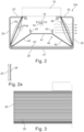
- a cover 20 is attached to the carrier 10, which in cross section has the Figure 2 recognizable shape. It is therefore an approximately U-shaped cross-sectional shape that has a base surface 21 and two side walls 25. On its upper side facing the carrier 10, however, the cover 20 is additionally designed with inward-facing wall areas 23 that extend as far as the carrier 10. Overall, the cover 20 thus encloses an elongated rectangular receiving space in which the components of the lamp 100 responsible for generating and emitting light are arranged.
- the luminaire 100 is closed off by corresponding front elements 15, which are plugged onto the open end areas of the cover 20 and connected to it. This creates space inside the Cover 20 is completely enclosed so that the luminaire 100 can also meet the requirements of corresponding so-called protection classes, i.e. is appropriately protected against the ingress of dust, dirt and/or moisture.
- the cover 20 consists entirely of a translucent, preferably clear material. Accordingly, it is intended that light is emitted across all surfaces, so that - with regard to the longitudinal axis of the lamp 100 - light can be emitted across 360°.
- the main light emission should be via the floor surface 21, so that there is direct light emission towards the underside, which is used, for example, to illuminate work surfaces or workplaces or objects located below the lamp 100.
- the two upper wall areas 23 of the cover 20, on the other hand, serve to emit a small proportion of the light upwards, for example, towards the ceiling of a room in which the lamp 100 is mounted. This can slightly brighten the ceiling area above the lamp 100. This portion of the light emitted indirectly into the room is also directed onto the work surface via reflections on the room boundary surfaces and, as a supplement to the other light components, is largely responsible for a pleasant room atmosphere.
- a structure or the like can be provided on the surface of the wall sections 23 of the cover 20 facing the interior in order to achieve a better distribution of the light emitted upwards. Measures described in more detail below are also provided for the light emission towards the underside in order to influence the light in the desired manner.
- an optical element 40 is arranged within the space enclosed by the cover 20, which is formed, for example, from a light-scattering material and which serves to reflect the light of the Figure 2 schematically illustrated illuminants 18, 19 before being emitted, in particular via the bottom side 21 of the cover 20.
- the light-scattering element 40 has an approximately H-shaped cross-section with a Horizontal surface 41, from which two arms 42 extend obliquely downwards essentially to the lower corners of the cover 20.
- the element 40 is an integral part of the cover 20 produced by the extrusion process and thus connected to it at the lower ends, as Figure 2
- the various side walls 21, 23, 25 of the cover are made of a clear material
- the light-influencing element 40 is preferably made of a light-scattering material throughout.
- upwardly extending webs 43 are provided on the side areas of the horizontal surface 41.
- the light influencing element 40 then serves to resolve the individual LEDs 19 as individual light points. This is particularly important for the light emission via the base surface 21 of the cover 20, since the aim here is to achieve the most uniform possible illumination of the area to be illuminated and, furthermore, the LEDs should no longer be perceptible as individual light sources.
- a further plate-shaped element 45 is preferably arranged, which has a micropyramidal optic on one flat side.
- micropyramidal optics are already known per se and are used in lighting technology to influence the light emitted over a surface in such a way that it leaves the lamp over a predetermined angular range, which is selected in particular in such a way that no disturbing reflections or other glare effects occur.
- this micropyramidal optic also contributes to the fact that the individual LEDs 19 cannot be perceived as individual light sources.
- the micropyramidal optics are, as already mentioned, part of a separate plate-shaped element 45, which is inserted or pushed into the base area of the cover 20, whereby a diffusely scattering film (not shown) can be provided on this element 45.
- the micropyramidal optics could also be integrated into the base area 21 of the cover 20.
- the light emitted directly to the underside is influenced in succession by several components: H-shaped Diffuser 40 (diffuse scattering) - possibly MPO film (diffuse scattering) - plate 45 with micropyramid structure - clear bottom surface 21 of the cover 20.
- the present invention is particularly concerned with the light emission via the side walls 25 of the cover 20, which is intended to lead to an optimized appearance of the lamp 100.
- the focus is less on the aspect of illuminating a specific area outside the lamp 100, but rather it is desired that a rather small part of the light from the lighting means 18 is emitted laterally in such a way that the lamp 100 appears particularly appealing to an observer.
- the side walls 25 of the cover 20 preferably consist of a clear material, but have a structure which Figure 2 recognizable and in Figure 2a is shown enlarged in section.
- This Fresnel-like structure 26 consists of elevations facing the interior of the lamp 100, which are designed like prisms. In the embodiment shown, they have in particular a triangular, particularly preferably sawtooth-like cross-sectional shape in order to influence light rays passing through the corresponding side walls 25 accordingly.
- the structuring 26 is translationally invariant when viewed in the longitudinal direction, i.e. does not change in the longitudinal direction of the lamp 100.
- the light influencing elements 30 are provided in the form of foils, which are then as in Figure 2 shown in the cover 20 of the lamp 100.
- the films have a certain strength or thickness of, for example, about 0.5 mm, so that the resulting light-influencing element 30 has a corresponding inherent stability to enable clamping in the manner shown.
- the height of the light-influencing element 30 it can be provided that this extends straight from the lower corner area of the cover 20 obliquely upwards, as shown in Figure 2 with the solid lines.
- the height of the light influencing element 30 is chosen to be somewhat larger, so that the film is clamped in a curved pre-tensioned manner either convexly or concavely into the cover 20.
- the additional light-influencing element 30 has a certain distance from the side wall 25 of the cover 20 and, as already mentioned, is provided with a pattern 35.
- Figure 4 shows examples of various possible patterns 35, whereby these patterns 35 either do not change in the longitudinal direction, but are at least periodic or repeating.
- a change in the pattern 35 can certainly be provided, which takes into account in particular the fact that the lower areas of the light-influencing element 30 are further away from the light sources 18 and a somewhat smaller proportion of light will pass through here.
- the interaction between structuring 26 and printing pattern 35 is particularly efficient when both components have comparable size ratios.
- these sawtooth-like structures have dimensions in the range of approximately 1.5 mm, whereby even in the case of the Figure 4 shown patterns 35 the corresponding individual structures should be chosen in approximately the same order of magnitude.
- the optical elements 30 can be printed with the various patterns 35 in a very simple but nevertheless precise manner. Ultimately, this opens up the possibility of being able to provide different patterns in a simple manner.
- the dark areas of the pattern are not designed to completely block light, but rather that there is a contrast between the light and dark areas of the print, which is in the range of approximately 30 - 50%. It has been found that this allows a sufficiently high amount of light to be emitted via the side walls 25 of the cover 20, and that the depth effect mentioned can still be realized in a sufficiently perceptible manner.
- the invention creates a lamp that has a positive appearance due to extremely appealing lighting effects.
- One advantage of the solution is that the effort required to achieve the special lighting effects is relatively low.
Landscapes
- Engineering & Computer Science (AREA)
- General Engineering & Computer Science (AREA)
- Physics & Mathematics (AREA)
- General Physics & Mathematics (AREA)
- Optics & Photonics (AREA)
- Non-Portable Lighting Devices Or Systems Thereof (AREA)
- Planar Illumination Modules (AREA)
Claims (13)
- Luminaire (100) comportant des moyens d'éclairage (18) ainsi qu'un élément de recouvrement (20), lequel présente au moins une zone plate (25) pour l'émission de lumière,la zone plate (25) pour l'émission de lumière étant constituée d'un matériau transparent et pourvue d'une structuration (26) sur au moins un côté,et un élément (30) influençant la lumière en forme de plaque, formé par une feuille en matériau synthétique, étant disposé entre les moyens d'éclairage (18) et la zone plate (25) pour l'émission de lumière, lequel élément est imprimé d'un motif (35),caractériséen ce que la feuille formant l'élément (30) influençant la lumière est montée serrée dans l'élément de recouvrement (20), de telle sorte que l'élément (30) influençant la lumière présente un écart par rapport à l'élément de recouvrement (20).
- Luminaire selon la revendication 1,
caractérisé
en ce que la structuration (26) est réalisée sur le côté intérieur de la zone plate (25) pour l'émission de lumière. - Luminaire selon la revendication 1 ou 2,
caractérisé
en ce que le luminaire (100) s'étend le long d'un axe longitudinal et la structuration (26) est réalisée de manière invariante en translation dans une direction parallèle à l'axe longitudinal. - Luminaire selon la revendication 3,
caractérisé
en ce que la structuration (26) présente une réalisation de type fresnel ou, selon le cas, est formée par une structure prismatique s'étendant dans la direction longitudinale. - Luminaire selon la revendication 4,
caractérisé
en ce que la structure prismatique présente en section transversale des élévations (27) triangulaires, en particulier en dents de scie. - Luminaire selon l'une des revendications précédentes ainsi que l'une quelconque des revendications 3 à 5,
caractérisé
en ce que le motif (35) est réalisé de manière périodique dans la direction longitudinale. - Luminaire selon la revendication 6,
caractérisé
en ce que le motif (35) est réalisé de manière à varier dans une direction perpendiculaire à la direction longitudinale. - Luminaire selon l'une des revendications précédentes,
caractérisé
en ce que l'élément de recouvrement (20) est réalisé en forme de U comportant deux parois latérales ainsi qu'une surface de fond (21) reliant la paroi latérale, les deux parois latérales formant des zones plates (25) pour l'émission de lumière. - Luminaire selon la revendication 8,
caractérisé
en ce que la surface de fond (21) de l'élément de recouvrement (20) est également réalisée de manière à laisser passer la lumière. - Luminaire selon la revendication 9,
caractérisé
en ce qu'un élément (40) diffusant la lumière est disposé devant la surface de fond (21). - Luminaire selon la revendication 10,
caractérisé
en ce que l'élément diffusant la lumière présente une paroi (41) disposée parallèlement à la surface de fond (21) de l'élément de recouvrement ainsi que deux bras (42) s'étendant en trapèze à partir de celle-ci. - Luminaire selon la revendication 10 ou 11,
caractérisé
en ce que l'élément (40) diffusant la lumière est relié d'un seul tenant à l'élément de recouvrement (20). - Luminaire selon l'une des revendications 10 à 12,
caractérisé
en ce qu'un autre élément optique (45) est disposé entre l'élément (40) diffusant la lumière et la surface de fond (21) de l'élément de recouvrement (20), lequel autre élément présente une structure micropyramidale.
Applications Claiming Priority (2)
| Application Number | Priority Date | Filing Date | Title |
|---|---|---|---|
| DE202019105265.1U DE202019105265U1 (de) | 2019-09-24 | 2019-09-24 | Leuchte mit Bereich zur flächigen Lichtabgabe |
| PCT/EP2020/070411 WO2021058167A1 (fr) | 2019-09-24 | 2020-07-20 | Luminaire ayant une région pour émettre de la lumière sur une surface |
Publications (2)
| Publication Number | Publication Date |
|---|---|
| EP4034807A1 EP4034807A1 (fr) | 2022-08-03 |
| EP4034807B1 true EP4034807B1 (fr) | 2025-01-08 |
Family
ID=71784008
Family Applications (1)
| Application Number | Title | Priority Date | Filing Date |
|---|---|---|---|
| EP20745124.6A Active EP4034807B1 (fr) | 2019-09-24 | 2020-07-20 | Luminaire ayant une région pour émettre de la lumière sur une surface |
Country Status (6)
| Country | Link |
|---|---|
| US (1) | US20220325856A1 (fr) |
| EP (1) | EP4034807B1 (fr) |
| CN (1) | CN114364915A (fr) |
| AT (1) | AT18309U1 (fr) |
| DE (1) | DE202019105265U1 (fr) |
| WO (1) | WO2021058167A1 (fr) |
Families Citing this family (2)
| Publication number | Priority date | Publication date | Assignee | Title |
|---|---|---|---|---|
| US11852333B1 (en) * | 2022-10-25 | 2023-12-26 | Abl Ip Holding Llc | Light fixture with glare reduction panels |
| DE102024200785A1 (de) * | 2024-01-29 | 2025-07-31 | Stellantis Auto Sas | Optisches Element einer Leuchtvorrichtung für einen Innenraum eines Fahrzeugs sowie die Leuchtvorrichtung aufweisendes Fahrzeug |
Family Cites Families (36)
| Publication number | Priority date | Publication date | Assignee | Title |
|---|---|---|---|---|
| US1472050A (en) * | 1921-09-17 | 1923-10-30 | Augustus D Curtis | Lighting fixture |
| US2474308A (en) * | 1946-11-29 | 1949-06-28 | Holophane Co Inc | Surface attached lighting equipment |
| US4186433A (en) * | 1978-02-21 | 1980-01-29 | General Electric Company | Luminaire |
| JPS63176228U (fr) * | 1987-05-07 | 1988-11-15 | ||
| US4768140A (en) * | 1987-05-19 | 1988-08-30 | Roman Szpur | Indoor light fixture for high intensity lamp |
| DE4039290A1 (de) * | 1990-12-08 | 1992-06-11 | Minnesota Mining & Mfg | Leuchte |
| US5258895A (en) * | 1992-03-09 | 1993-11-02 | Bosse Thomas W | Moire light assembly |
| DE29923835U1 (de) * | 1999-04-07 | 2001-04-05 | Zumtobel Staff Gmbh | Beleuchtungsanordnung zur Anbringung an der Decke oder einer Wand eines Raumes |
| EP1337786A2 (fr) * | 2000-11-29 | 2003-08-27 | Zumtobel Staff GmbH | Lampe pourvue d'une vitre transparente |
| US6898012B2 (en) * | 2002-05-16 | 2005-05-24 | Eastman Kodak Company | Light reflector with variable diffuse light reflection |
| US7866871B2 (en) * | 2006-01-13 | 2011-01-11 | Avery Dennison Corporation | Light enhancing structures with a plurality of arrays of elongate features |
| US7883226B2 (en) * | 2007-03-05 | 2011-02-08 | Intematix Corporation | LED signal lamp |
| JP5179565B2 (ja) * | 2007-04-10 | 2013-04-10 | レダライト アーキテクチュラル プロダクツ,インコーポレイテッド | 上方及び下方範囲においてバットウイング光度分布を呈する調光装置 |
| DE202007011211U1 (de) * | 2007-08-10 | 2008-12-24 | Zumtobel Lighting Gmbh | Leuchte |
| DE202007011212U1 (de) * | 2007-08-10 | 2008-12-24 | Zumtobel Lighting Gmbh | Leuchte mit Raster zur Lichtabgabe |
| US8534877B1 (en) * | 2008-04-03 | 2013-09-17 | Stingray Energy Systems LLC | Luminaire optical systems |
| AT11163U1 (de) * | 2008-10-09 | 2010-05-15 | Zumtobel Lighting Gmbh | Leuchte |
| JP2011084942A (ja) * | 2009-10-15 | 2011-04-28 | Itoki Corp | 透過視認性制御パネルを用いたオフィス家具 |
| KR100982727B1 (ko) * | 2010-01-15 | 2010-09-17 | 엄용식 | Led 조명기구 |
| FR2970011B1 (fr) * | 2010-12-30 | 2013-01-11 | Normalu | Dispositif lumineux destine a etre integre a une fausse paroi et permettant d'obtenir un effet esthetique en trois dimensions |
| DE102011051038A1 (de) * | 2011-06-14 | 2012-12-20 | Selux Aktiengesellschaft | LED Beleuchtungsanordnung |
| KR101279486B1 (ko) * | 2011-08-17 | 2013-06-27 | 엘지이노텍 주식회사 | 조명 부재 및 이를 이용한 조명기기 |
| AT514917B1 (de) * | 2013-11-22 | 2015-05-15 | Neulicht Lighting Solutions Gmbh | LED-Leuchte |
| JP2015149246A (ja) * | 2014-02-07 | 2015-08-20 | パナソニックIpマネジメント株式会社 | 照明用光源及び照明装置 |
| US9746161B2 (en) * | 2014-05-09 | 2017-08-29 | Philips Lighting Holding B.V. | Method for manufacturing a linear lighting device |
| US20150360606A1 (en) * | 2014-06-12 | 2015-12-17 | Nthdegree Technologies Worldwide Inc. | Thin flexible led light sheet applications |
| CN205424492U (zh) * | 2014-12-05 | 2016-08-03 | 嘉兴山蒲照明电器有限公司 | Led直管灯 |
| US10101002B2 (en) * | 2015-11-09 | 2018-10-16 | Apple Inc. | Light fixture with fabric layer having printed dots |
| DE202016002197U1 (de) * | 2016-04-01 | 2016-06-06 | Osram Gmbh | Direktstrahlende LED-Leuchte mit Entblendungsoptik |
| CA3021728A1 (fr) * | 2016-04-21 | 2017-10-26 | Hubbell Incorporated | Luminaire de type leche-mur |
| JP6765055B2 (ja) * | 2016-08-19 | 2020-10-07 | パナソニックIpマネジメント株式会社 | 照明器具 |
| CN106439545B (zh) * | 2016-11-22 | 2022-11-15 | 东莞泛美光电有限公司 | 替换式led灯具 |
| US20180245754A1 (en) * | 2017-02-27 | 2018-08-30 | Elemental LED, Inc. | Linear LED Lighting with Built-In Light Modifiers |
| DE102017125245A1 (de) * | 2017-10-27 | 2019-05-02 | Siteco Beleuchtungstechnik Gmbh | Abdeckung für ein Leuchtmodul, Leuchtmodul und Leuchte |
| JP2019184332A (ja) * | 2018-04-05 | 2019-10-24 | 日本精機株式会社 | 計器装置 |
| EP3626425B1 (fr) * | 2018-09-20 | 2023-01-18 | Zumtobel Lighting GmbH | Composant de lampe pour la formation d'une lampe ayant un grand angle d'émission, lampe et procédé de fabrication d'un tel composant de lampe |
-
2019
- 2019-09-24 DE DE202019105265.1U patent/DE202019105265U1/de active Active
- 2019-12-10 AT ATGM50222/2019U patent/AT18309U1/de unknown
-
2020
- 2020-07-20 US US17/639,974 patent/US20220325856A1/en not_active Abandoned
- 2020-07-20 EP EP20745124.6A patent/EP4034807B1/fr active Active
- 2020-07-20 WO PCT/EP2020/070411 patent/WO2021058167A1/fr not_active Ceased
- 2020-07-20 CN CN202080062586.8A patent/CN114364915A/zh active Pending
Also Published As
| Publication number | Publication date |
|---|---|
| CN114364915A (zh) | 2022-04-15 |
| AT18309U1 (de) | 2024-09-15 |
| US20220325856A1 (en) | 2022-10-13 |
| WO2021058167A1 (fr) | 2021-04-01 |
| EP4034807A1 (fr) | 2022-08-03 |
| DE202019105265U1 (de) | 2021-01-04 |
Similar Documents
| Publication | Publication Date | Title |
|---|---|---|
| EP1688662B1 (fr) | Luminaire | |
| EP4034807B1 (fr) | Luminaire ayant une région pour émettre de la lumière sur une surface | |
| AT15359U1 (de) | Längliche LED-Leuchte mit optischem Element | |
| EP2796769A2 (fr) | Lampe à DEL dotée d'un système de conducteurs lumineux | |
| EP2994693B1 (fr) | Élément de recouvrement pour luminaire surfacique | |
| EP2166276B1 (fr) | Agencement de formation d'une source lumineuse longitudinale | |
| DE102014104448B4 (de) | Leuchte mit einem Lichtleiter zur Erzeugung von entblendetem, teilflächigen Licht | |
| EP3631554B1 (fr) | Dispositif optique pour source de lumière | |
| AT16319U1 (de) | Optisches System sowie Anordnung zur Lichtabgabe | |
| EP2518389B2 (fr) | Agencement d'émission de lumière avec un élément optique allongé | |
| CH715292B1 (de) | Optikrohling, Verfahren und Linearleuchte. | |
| DE102017203200A1 (de) | Leuchtenwanne zum Bilden eines Leuchtengehäuses | |
| EP3557124B1 (fr) | Luminaire à del plat | |
| EP2176583B1 (fr) | Éclairage à grille pour l'émission de lumière | |
| DE102017203207A1 (de) | Leuchtenabdeckung und Leuchte | |
| EP3112747B1 (fr) | Élement optique destine a influencer l'emission lumineuse d'une source lumineuse allongee | |
| EP1467141A2 (fr) | Luminaire à surface luminescente fermée | |
| EP3882517B1 (fr) | Luminaire à del | |
| DE102018119606A1 (de) | Optisches Element für eine Leuchte, insbesondere Büroleuchte, sowie Leuchte | |
| EP3627042B1 (fr) | Luminaire pourvu d'un élément de guide de lumière sous la forme de plaque | |
| EP2107297B1 (fr) | Eclairage, en particulier éclairage d'intérieur | |
| EP2355076A2 (fr) | Lampe dotée d'un moyen d'influence de la lumière flexible | |
| DE10133360A1 (de) | Downlight mit Seitenreflektor | |
| EP2994690B1 (fr) | Luminaire équipé d'un boîtier comportant plusieurs orifices de rayonnement de lumière | |
| DE202014102021U1 (de) | Optisches Element für eine Lichtquelle einer Leuchte, sowie Leuchte |
Legal Events
| Date | Code | Title | Description |
|---|---|---|---|
| STAA | Information on the status of an ep patent application or granted ep patent |
Free format text: STATUS: UNKNOWN |
|
| STAA | Information on the status of an ep patent application or granted ep patent |
Free format text: STATUS: THE INTERNATIONAL PUBLICATION HAS BEEN MADE |
|
| PUAI | Public reference made under article 153(3) epc to a published international application that has entered the european phase |
Free format text: ORIGINAL CODE: 0009012 |
|
| STAA | Information on the status of an ep patent application or granted ep patent |
Free format text: STATUS: REQUEST FOR EXAMINATION WAS MADE |
|
| 17P | Request for examination filed |
Effective date: 20220228 |
|
| AK | Designated contracting states |
Kind code of ref document: A1 Designated state(s): AL AT BE BG CH CY CZ DE DK EE ES FI FR GB GR HR HU IE IS IT LI LT LU LV MC MK MT NL NO PL PT RO RS SE SI SK SM TR |
|
| DAV | Request for validation of the european patent (deleted) | ||
| DAX | Request for extension of the european patent (deleted) | ||
| GRAP | Despatch of communication of intention to grant a patent |
Free format text: ORIGINAL CODE: EPIDOSNIGR1 |
|
| STAA | Information on the status of an ep patent application or granted ep patent |
Free format text: STATUS: GRANT OF PATENT IS INTENDED |
|
| INTG | Intention to grant announced |
Effective date: 20241002 |
|
| GRAS | Grant fee paid |
Free format text: ORIGINAL CODE: EPIDOSNIGR3 |
|
| GRAA | (expected) grant |
Free format text: ORIGINAL CODE: 0009210 |
|
| STAA | Information on the status of an ep patent application or granted ep patent |
Free format text: STATUS: THE PATENT HAS BEEN GRANTED |
|
| AK | Designated contracting states |
Kind code of ref document: B1 Designated state(s): AL AT BE BG CH CY CZ DE DK EE ES FI FR GB GR HR HU IE IS IT LI LT LU LV MC MK MT NL NO PL PT RO RS SE SI SK SM TR |
|
| P01 | Opt-out of the competence of the unified patent court (upc) registered |
Free format text: CASE NUMBER: APP_63542/2024 Effective date: 20241129 |
|
| REG | Reference to a national code |
Ref country code: GB Ref legal event code: FG4D Free format text: NOT ENGLISH |
|
| REG | Reference to a national code |
Ref country code: CH Ref legal event code: EP |
|
| REG | Reference to a national code |
Ref country code: DE Ref legal event code: R096 Ref document number: 502020010161 Country of ref document: DE |
|
| REG | Reference to a national code |
Ref country code: IE Ref legal event code: FG4D Free format text: LANGUAGE OF EP DOCUMENT: GERMAN |
|
| REG | Reference to a national code |
Ref country code: LT Ref legal event code: MG9D |
|
| REG | Reference to a national code |
Ref country code: NL Ref legal event code: MP Effective date: 20250108 |
|
| PG25 | Lapsed in a contracting state [announced via postgrant information from national office to epo] |
Ref country code: NL Free format text: LAPSE BECAUSE OF FAILURE TO SUBMIT A TRANSLATION OF THE DESCRIPTION OR TO PAY THE FEE WITHIN THE PRESCRIBED TIME-LIMIT Effective date: 20250108 |
|
| PG25 | Lapsed in a contracting state [announced via postgrant information from national office to epo] |
Ref country code: RS Free format text: LAPSE BECAUSE OF FAILURE TO SUBMIT A TRANSLATION OF THE DESCRIPTION OR TO PAY THE FEE WITHIN THE PRESCRIBED TIME-LIMIT Effective date: 20250408 |
|
| PG25 | Lapsed in a contracting state [announced via postgrant information from national office to epo] |
Ref country code: FI Free format text: LAPSE BECAUSE OF FAILURE TO SUBMIT A TRANSLATION OF THE DESCRIPTION OR TO PAY THE FEE WITHIN THE PRESCRIBED TIME-LIMIT Effective date: 20250108 |
|
| PG25 | Lapsed in a contracting state [announced via postgrant information from national office to epo] |
Ref country code: PL Free format text: LAPSE BECAUSE OF FAILURE TO SUBMIT A TRANSLATION OF THE DESCRIPTION OR TO PAY THE FEE WITHIN THE PRESCRIBED TIME-LIMIT Effective date: 20250108 |
|
| PG25 | Lapsed in a contracting state [announced via postgrant information from national office to epo] |
Ref country code: ES Free format text: LAPSE BECAUSE OF FAILURE TO SUBMIT A TRANSLATION OF THE DESCRIPTION OR TO PAY THE FEE WITHIN THE PRESCRIBED TIME-LIMIT Effective date: 20250108 |
|
| PG25 | Lapsed in a contracting state [announced via postgrant information from national office to epo] |
Ref country code: NO Free format text: LAPSE BECAUSE OF FAILURE TO SUBMIT A TRANSLATION OF THE DESCRIPTION OR TO PAY THE FEE WITHIN THE PRESCRIBED TIME-LIMIT Effective date: 20250408 Ref country code: IS Free format text: LAPSE BECAUSE OF FAILURE TO SUBMIT A TRANSLATION OF THE DESCRIPTION OR TO PAY THE FEE WITHIN THE PRESCRIBED TIME-LIMIT Effective date: 20250508 |
|
| PG25 | Lapsed in a contracting state [announced via postgrant information from national office to epo] |
Ref country code: HR Free format text: LAPSE BECAUSE OF FAILURE TO SUBMIT A TRANSLATION OF THE DESCRIPTION OR TO PAY THE FEE WITHIN THE PRESCRIBED TIME-LIMIT Effective date: 20250108 |
|
| PG25 | Lapsed in a contracting state [announced via postgrant information from national office to epo] |
Ref country code: PT Free format text: LAPSE BECAUSE OF FAILURE TO SUBMIT A TRANSLATION OF THE DESCRIPTION OR TO PAY THE FEE WITHIN THE PRESCRIBED TIME-LIMIT Effective date: 20250508 Ref country code: LV Free format text: LAPSE BECAUSE OF FAILURE TO SUBMIT A TRANSLATION OF THE DESCRIPTION OR TO PAY THE FEE WITHIN THE PRESCRIBED TIME-LIMIT Effective date: 20250108 |
|
| PG25 | Lapsed in a contracting state [announced via postgrant information from national office to epo] |
Ref country code: BG Free format text: LAPSE BECAUSE OF FAILURE TO SUBMIT A TRANSLATION OF THE DESCRIPTION OR TO PAY THE FEE WITHIN THE PRESCRIBED TIME-LIMIT Effective date: 20250108 Ref country code: GR Free format text: LAPSE BECAUSE OF FAILURE TO SUBMIT A TRANSLATION OF THE DESCRIPTION OR TO PAY THE FEE WITHIN THE PRESCRIBED TIME-LIMIT Effective date: 20250409 |
|
| PG25 | Lapsed in a contracting state [announced via postgrant information from national office to epo] |
Ref country code: SE Free format text: LAPSE BECAUSE OF FAILURE TO SUBMIT A TRANSLATION OF THE DESCRIPTION OR TO PAY THE FEE WITHIN THE PRESCRIBED TIME-LIMIT Effective date: 20250108 |
|
| PG25 | Lapsed in a contracting state [announced via postgrant information from national office to epo] |
Ref country code: SM Free format text: LAPSE BECAUSE OF FAILURE TO SUBMIT A TRANSLATION OF THE DESCRIPTION OR TO PAY THE FEE WITHIN THE PRESCRIBED TIME-LIMIT Effective date: 20250108 |
|
| REG | Reference to a national code |
Ref country code: DE Ref legal event code: R097 Ref document number: 502020010161 Country of ref document: DE |
|
| PG25 | Lapsed in a contracting state [announced via postgrant information from national office to epo] |
Ref country code: DK Free format text: LAPSE BECAUSE OF FAILURE TO SUBMIT A TRANSLATION OF THE DESCRIPTION OR TO PAY THE FEE WITHIN THE PRESCRIBED TIME-LIMIT Effective date: 20250108 |
|
| PGFP | Annual fee paid to national office [announced via postgrant information from national office to epo] |
Ref country code: DE Payment date: 20250728 Year of fee payment: 6 |
|
| PGFP | Annual fee paid to national office [announced via postgrant information from national office to epo] |
Ref country code: GB Payment date: 20250722 Year of fee payment: 6 |
|
| PGFP | Annual fee paid to national office [announced via postgrant information from national office to epo] |
Ref country code: AT Payment date: 20250718 Year of fee payment: 6 Ref country code: FR Payment date: 20250725 Year of fee payment: 6 |
|
| PGFP | Annual fee paid to national office [announced via postgrant information from national office to epo] |
Ref country code: CH Payment date: 20250801 Year of fee payment: 6 |
|
| PG25 | Lapsed in a contracting state [announced via postgrant information from national office to epo] |
Ref country code: CZ Free format text: LAPSE BECAUSE OF FAILURE TO SUBMIT A TRANSLATION OF THE DESCRIPTION OR TO PAY THE FEE WITHIN THE PRESCRIBED TIME-LIMIT Effective date: 20250108 Ref country code: EE Free format text: LAPSE BECAUSE OF FAILURE TO SUBMIT A TRANSLATION OF THE DESCRIPTION OR TO PAY THE FEE WITHIN THE PRESCRIBED TIME-LIMIT Effective date: 20250108 |
|
| PG25 | Lapsed in a contracting state [announced via postgrant information from national office to epo] |
Ref country code: RO Free format text: LAPSE BECAUSE OF FAILURE TO SUBMIT A TRANSLATION OF THE DESCRIPTION OR TO PAY THE FEE WITHIN THE PRESCRIBED TIME-LIMIT Effective date: 20250108 |
|
| PG25 | Lapsed in a contracting state [announced via postgrant information from national office to epo] |
Ref country code: SK Free format text: LAPSE BECAUSE OF FAILURE TO SUBMIT A TRANSLATION OF THE DESCRIPTION OR TO PAY THE FEE WITHIN THE PRESCRIBED TIME-LIMIT Effective date: 20250108 |
|
| PLBE | No opposition filed within time limit |
Free format text: ORIGINAL CODE: 0009261 |
|
| STAA | Information on the status of an ep patent application or granted ep patent |
Free format text: STATUS: NO OPPOSITION FILED WITHIN TIME LIMIT |
|
| 26N | No opposition filed |
Effective date: 20251009 |
|
| PG25 | Lapsed in a contracting state [announced via postgrant information from national office to epo] |
Ref country code: IT Free format text: LAPSE BECAUSE OF FAILURE TO SUBMIT A TRANSLATION OF THE DESCRIPTION OR TO PAY THE FEE WITHIN THE PRESCRIBED TIME-LIMIT Effective date: 20250108 |
|
| PG25 | Lapsed in a contracting state [announced via postgrant information from national office to epo] |
Ref country code: LU Free format text: LAPSE BECAUSE OF NON-PAYMENT OF DUE FEES Effective date: 20250720 |
|
| REG | Reference to a national code |
Ref country code: BE Ref legal event code: MM Effective date: 20250731 |
|
| PG25 | Lapsed in a contracting state [announced via postgrant information from national office to epo] |
Ref country code: BE Free format text: LAPSE BECAUSE OF NON-PAYMENT OF DUE FEES Effective date: 20250731 |