EP4035229B1 - Connecteur électrique enfichable - Google Patents
Connecteur électrique enfichable Download PDFInfo
- Publication number
- EP4035229B1 EP4035229B1 EP20776070.3A EP20776070A EP4035229B1 EP 4035229 B1 EP4035229 B1 EP 4035229B1 EP 20776070 A EP20776070 A EP 20776070A EP 4035229 B1 EP4035229 B1 EP 4035229B1
- Authority
- EP
- European Patent Office
- Prior art keywords
- housing
- plug connector
- plug
- contact carrier
- connector according
- Prior art date
- Legal status (The legal status is an assumption and is not a legal conclusion. Google has not performed a legal analysis and makes no representation as to the accuracy of the status listed.)
- Active
Links
Images





Classifications
-
- H—ELECTRICITY
- H01—ELECTRIC ELEMENTS
- H01R—ELECTRICALLY-CONDUCTIVE CONNECTIONS; STRUCTURAL ASSOCIATIONS OF A PLURALITY OF MUTUALLY-INSULATED ELECTRICAL CONNECTING ELEMENTS; COUPLING DEVICES; CURRENT COLLECTORS
- H01R13/00—Details of coupling devices of the kinds covered by groups H01R12/70 or H01R24/00 - H01R33/00
- H01R13/46—Bases; Cases
- H01R13/502—Bases; Cases composed of different pieces
-
- H—ELECTRICITY
- H01—ELECTRIC ELEMENTS
- H01R—ELECTRICALLY-CONDUCTIVE CONNECTIONS; STRUCTURAL ASSOCIATIONS OF A PLURALITY OF MUTUALLY-INSULATED ELECTRICAL CONNECTING ELEMENTS; COUPLING DEVICES; CURRENT COLLECTORS
- H01R13/00—Details of coupling devices of the kinds covered by groups H01R12/70 or H01R24/00 - H01R33/00
- H01R13/02—Contact members
- H01R13/10—Sockets for co-operation with pins or blades
-
- H—ELECTRICITY
- H01—ELECTRIC ELEMENTS
- H01R—ELECTRICALLY-CONDUCTIVE CONNECTIONS; STRUCTURAL ASSOCIATIONS OF A PLURALITY OF MUTUALLY-INSULATED ELECTRICAL CONNECTING ELEMENTS; COUPLING DEVICES; CURRENT COLLECTORS
- H01R13/00—Details of coupling devices of the kinds covered by groups H01R12/70 or H01R24/00 - H01R33/00
- H01R13/40—Securing contact members in or to a base or case; Insulating of contact members
-
- H—ELECTRICITY
- H01—ELECTRIC ELEMENTS
- H01R—ELECTRICALLY-CONDUCTIVE CONNECTIONS; STRUCTURAL ASSOCIATIONS OF A PLURALITY OF MUTUALLY-INSULATED ELECTRICAL CONNECTING ELEMENTS; COUPLING DEVICES; CURRENT COLLECTORS
- H01R13/00—Details of coupling devices of the kinds covered by groups H01R12/70 or H01R24/00 - H01R33/00
- H01R13/46—Bases; Cases
- H01R13/502—Bases; Cases composed of different pieces
- H01R13/506—Bases; Cases composed of different pieces assembled by snap action of the parts
-
- H—ELECTRICITY
- H01—ELECTRIC ELEMENTS
- H01R—ELECTRICALLY-CONDUCTIVE CONNECTIONS; STRUCTURAL ASSOCIATIONS OF A PLURALITY OF MUTUALLY-INSULATED ELECTRICAL CONNECTING ELEMENTS; COUPLING DEVICES; CURRENT COLLECTORS
- H01R13/00—Details of coupling devices of the kinds covered by groups H01R12/70 or H01R24/00 - H01R33/00
- H01R13/46—Bases; Cases
- H01R13/516—Means for holding or embracing insulating body, e.g. casing, hoods
-
- H—ELECTRICITY
- H01—ELECTRIC ELEMENTS
- H01R—ELECTRICALLY-CONDUCTIVE CONNECTIONS; STRUCTURAL ASSOCIATIONS OF A PLURALITY OF MUTUALLY-INSULATED ELECTRICAL CONNECTING ELEMENTS; COUPLING DEVICES; CURRENT COLLECTORS
- H01R13/00—Details of coupling devices of the kinds covered by groups H01R12/70 or H01R24/00 - H01R33/00
- H01R13/62—Means for facilitating engagement or disengagement of coupling parts or for holding them in engagement
- H01R13/627—Snap or like fastening
- H01R13/6271—Latching means integral with the housing
-
- H—ELECTRICITY
- H01—ELECTRIC ELEMENTS
- H01R—ELECTRICALLY-CONDUCTIVE CONNECTIONS; STRUCTURAL ASSOCIATIONS OF A PLURALITY OF MUTUALLY-INSULATED ELECTRICAL CONNECTING ELEMENTS; COUPLING DEVICES; CURRENT COLLECTORS
- H01R13/00—Details of coupling devices of the kinds covered by groups H01R12/70 or H01R24/00 - H01R33/00
- H01R13/73—Means for mounting coupling parts to apparatus or structures, e.g. to a wall
- H01R13/74—Means for mounting coupling parts in openings of a panel
-
- H—ELECTRICITY
- H01—ELECTRIC ELEMENTS
- H01R—ELECTRICALLY-CONDUCTIVE CONNECTIONS; STRUCTURAL ASSOCIATIONS OF A PLURALITY OF MUTUALLY-INSULATED ELECTRICAL CONNECTING ELEMENTS; COUPLING DEVICES; CURRENT COLLECTORS
- H01R13/00—Details of coupling devices of the kinds covered by groups H01R12/70 or H01R24/00 - H01R33/00
- H01R13/46—Bases; Cases
- H01R13/52—Dustproof, splashproof, drip-proof, waterproof, or flameproof cases
-
- H—ELECTRICITY
- H01—ELECTRIC ELEMENTS
- H01R—ELECTRICALLY-CONDUCTIVE CONNECTIONS; STRUCTURAL ASSOCIATIONS OF A PLURALITY OF MUTUALLY-INSULATED ELECTRICAL CONNECTING ELEMENTS; COUPLING DEVICES; CURRENT COLLECTORS
- H01R13/00—Details of coupling devices of the kinds covered by groups H01R12/70 or H01R24/00 - H01R33/00
- H01R13/46—Bases; Cases
- H01R13/52—Dustproof, splashproof, drip-proof, waterproof, or flameproof cases
- H01R13/5219—Sealing means between coupling parts, e.g. interfacial seal
-
- H—ELECTRICITY
- H01—ELECTRIC ELEMENTS
- H01R—ELECTRICALLY-CONDUCTIVE CONNECTIONS; STRUCTURAL ASSOCIATIONS OF A PLURALITY OF MUTUALLY-INSULATED ELECTRICAL CONNECTING ELEMENTS; COUPLING DEVICES; CURRENT COLLECTORS
- H01R13/00—Details of coupling devices of the kinds covered by groups H01R12/70 or H01R24/00 - H01R33/00
- H01R13/73—Means for mounting coupling parts to apparatus or structures, e.g. to a wall
- H01R13/74—Means for mounting coupling parts in openings of a panel
- H01R13/748—Means for mounting coupling parts in openings of a panel using one or more screws
Definitions
- the invention relates to an electrical connector according to the preamble of claim 1.
- Electrical connectors whether they are built-in connectors, also called chassis sockets, or cable connectors, typically consist of a housing with at least one insertion opening for a complementary connector and a contact carrier arranged in this housing for the electrical contacts accessible through the insertion opening(s).
- housings and contact carriers are very different, which has led to countless combinations of housing variants and contact carrier variants that only fit together in very specific combinations. Even for connectors of the same standard but with a different number of contacts or contact arrangement, completely different housings usually have to be used, which causes a lot of effort in the production and storage of the individual parts.
- the EP 3382818 A1 is considered to be the closest prior art and discloses a sealed passage of a standard interface through a wall, wherein the sealing housing, which consists of several parts and surrounds this standard interface, which is functional in itself, is arranged on both sides of the wall. In one of the parts of the sealing housing, an annular, flat groove is worked out, open towards the wall, for receiving a sealing ring.
- An electrical plug with coding function is the subject of the EP 3252876 A1
- the stationary part of the plug connection has a housing with a (square) ring-shaped insertion opening for the coding element of the mating connector, which could be interpreted as a ring-shaped extension of the mating connector.
- the electrical contacts are held in a structure whose exact design is not disclosed or comprehensible. According to the interpretation of the drawings, this is a one-piece section of the housing of the plug.
- the CN 204615057 U discloses a connector in which a contact carrier is inserted into a housing as a separate component, with an annular gap being formed on the insertion side between the inner wall of the housing and the outer surface of the contact carrier as an insertion opening for the annular extension of a mating connector.
- the contact carrier contains the electrical contacts and is fixed in the housing, which has only a single wall, by a rear cover which can be connected to the housing by means of a snap-in connection.
- a projecting mounting flange is arranged on the insertion side of the housing.
- the object of the present invention was to overcome the disadvantages of the prior art and to provide a device by means of which the construction of an electrical connector can be simplified and each component can be optimally designed according to its requirements.
- the device according to the invention comprises two concentrically arranged housing parts, a base at which the end of the housing parts opposite the at least one insertion opening connects them to one another, an annular space between the concentric housing parts, which forms an annular receptacle for the plug extension of a complementary plug connector, and a receptacle for the contact carrier in the interior of the inner housing part.
- the housing which is mainly responsible for the mechanical stability, which is also of particular importance for the easy establishment and release of the plug connection, can be optimally designed for this task.
- the contact carrier on the other hand, can be completely geared to the electrical requirements and only manage the fixing of the electrical contacts and their electrically insulated arrangement in the housing. Since the design of the housing is independent of the electrical requirements of the contact carrier, It can always be designed the same, especially with regard to the dimensions inside the inner housing part of the housing, and can thus be provided as a standard component that can be used for many connector types.
- the contact carrier is designed as a slide-in part.
- Guide structures are preferably formed between the inner wall of the inner housing part and the contact carrier. This facilitates the assembly of the housing and contact carrier and ensures the correct positioning of the contact carrier in the housing.
- An advantageous embodiment of the invention provides that a connecting mechanism is provided between the contact carrier and the housing in order to securely maintain the positioning of the contact carrier during the plugging and unplugging processes.
- connection mechanism as a locking or snap connection.
- the identical positioning of the contact carrier in the housing for all similarly constructed connectors is ensured by advantageously providing at least one stop for the contact carrier.
- a preferred embodiment of a connector according to the invention provides for its construction as a built-in connector or chassis socket and is characterized by a mounting flange that projects radially from the outer housing part and is preferably positioned at the plug-in end of the outer housing part.
- a seal is present which covers a front side of the mounting flange and has at least one recess corresponding to the insertion opening.
- a front plate which covers the front of the mounting flange and, if necessary, also the seal at the front serves to protect the components underneath and to ensure the stability of the entire arrangement.
- the connector is characterized by a locking mechanism for an inserted complementary connector, comprising at least one locking element, which is preferably arranged on the contact carrier.
- this embodiment also includes an unlocking element which protrudes from the locking element through recesses in the housing and possibly the front panel on the front of the housing or the front panel.
- an unlocking element which protrudes from the locking element through recesses in the housing and possibly the front panel on the front of the housing or the front panel.
- a one-piece dome is advantageously arranged on the seal to maintain the sealing effect, which serves to accommodate the unlocking element and protrudes forwards.
- the dome preferably protrudes through the front panel on its front.
- the contact carrier is designed either for plug connections according to the XLR standard or as a socket for an RJ45 plug.
- a first advantageous embodiment of a built-in connector according to the invention is shown, in a variant of the XLR standard with three contacts, as a female part of the plug connection or as a built-in socket.
- the housing 1 is constructed from two concentrically arranged housing parts, an outer housing part 5 and an inner housing part 6, which are spaced apart by an annular gap 7, whereby this annular gap 7 forms an annular insertion opening for a socket-shaped plug extension of a complementary cable connector.
- An annular base 8 connects the two housing parts 5, 6 to one another at the end of the housing 1 opposite the insertion opening 2.
- the cylindrical volume inside the inner housing part 6 forms the receptacle 9 for the contact carrier 3.
- a mounting flange 10 is arranged, shown here as an example with a square outline, which projects radially from the housing 1, in particular from the outer housing part 5, and in which mounting holes 11 can also be cut out. Other outline shapes can also occur, for example circular or rectangular outlines. At most, only one or more small mounting tabs can be arranged on a housing 1 that is otherwise only cylindrical.
- the front of the housing 1 or the mounting flange 10 can advantageously be covered by a seal 13, which seals the built-in plug socket against the wall in which the socket is installed and fixed.
- the seal 13 preferably has a plate-shaped section 14, which covers the mounting flange 10, also provided with a recess 15 at the location of the mounting holes 11 and a central recess 16 for the passage of the complementary cable connector.
- Flexible strips 17 preferably extend from the plate-shaped section 14, at the end of which there is a sealing plug 18, for example in the shape of a pot, for insertion into the recess 16 and preferably also the annular gap 7 between the inner housing part 6 and the outer housing part 5, in order to be able to seal the built-in plug socket tightly when the complementary connector is not inserted.
- a front plate 19 is preferably provided which covers the front of the mounting flange 10 and possibly also the seal 13, in particular its plate-shaped section 14, towards the front.
- This front plate 19 also has at the locations of the mounting holes 11 of the mounting flange 10, possibly also the recesses 15 of the Seal 13, own mounting holes 20.
- the connector according to the invention preferably also has a locking mechanism 22 for a plugged-in complementary connector in order to prevent the cable connector from being unintentionally pulled out and thus the plug connection from coming loose.
- This mechanism 22 comprises at least one locking element 23, which is preferably arranged on the contact carrier 3.
- an unlocking element 24 in operative connection with the locking element 23 is integrated into the locking mechanism 22.
- the unlocking element 24 protrudes, starting from the locking element 23, through recesses or protuberances 25 in the housing 1 and a radial recess 26 in the central recess 21 of the front plate 19 on the front of the housing 1 or the front plate 19, from where it is accessible to the user for operation.
- the section of the unlocking element 24 protruding through the front plate 19 is formed by a dome 27 integrally formed on the seal 13, in particular on the plate-shaped section 14, for receiving the unlocking element 24, which dome 27 protrudes forwards and preferably protrudes through the front plate 19 on its front side.
- the contact carrier 3 is preferably designed as an insertion part and, if necessary, guide structures are formed between the inner wall of the inner housing part 6 and the contact carrier 3.
- a connection mechanism can also act between the contact carrier 3 and the housing 1 in order to hold the contact carrier 3 securely around the housing 1. If necessary, this can be done by crimping the rear edge of the housing 1 radially inwards over an outer peripheral edge of the inserted contact carrier 3.
- the connection mechanism is designed as a latching or snap connection.
- the contact carrier 3 has a shoulder 31 which extends over a large part of the circumference and is formed by an increase in diameter between the insertion-side longitudinal section and the section adjoining it.
- a shoulder 32 is formed on the inside of the housing 1, approximately at the level of the base 8, which connects the inner housing part 6 with the outer housing part 5.
- the shoulder 31 of the contact carrier 3 comes to a stop on this shoulder 32 when inserted into the housing 1, thereby ensuring the desired positioning of the two components relative to one another.
- the recess 34 on the front which is present in particular in XLR contact carriers 3 and which is connected to the bearing area for the locking mechanism 22, is covered by a nose 28 projecting towards the centre of the insertion opening 2.
- This can advantageously have two guides 29 running parallel to the longitudinal axis of the housing 1, between which in particular the spring of the locking mechanism 22 is guided and held.
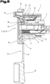
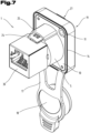
- Fig. 6 to 9 a further and possibly independent embodiment of a built-in connector according to the invention is shown, wherein again the same reference numerals or component designations are used for the same parts as in the previous Fig. 1 to 5 To avoid unnecessary repetition, reference is made to the detailed description of the previous figures.
- the Fig. 6 to 9 show a panel socket for a data connector, in particular an RJ-45 connector.
- the contact carrier 3 of this version of the built-in plug socket according to the invention is covered and protected on the rear side of the housing 1 by a contact feedthrough 29 and a rear cover 30.
Landscapes
- Connector Housings Or Holding Contact Members (AREA)
- Coupling Device And Connection With Printed Circuit (AREA)
Claims (11)
- Connecteur électrique enfichable, doté d'un boîtier (1) avec au moins une ouverture d'enfichage (2) pour un connecteur enfichable complémentaire et avec un support de contact (3) de forme insérable, inséré dans le boîtier (1) et destiné à entrer en contact avec les contacts électriques accessibles par la ou les ouvertures d'enfichage, le boîtier (1) présentant deux parties de boîtier (5, 6) concentriques et superposées dans leur longueur, une paroi inférieure (8) située à l'extrémité opposée de l'au moins une ouverture d'enfichage (2) reliant entre elles les parties de boîtier (5, 6), et un espace intermédiaire (7) annulaire entre les parties de boîtier (5, 6) concentriques formant un réceptacle annulaire destiné au prolongement d'un connecteur enfichable complémentaire, un réceptacle (9) destiné au support de contact (3) étant formé à l'intérieur de la partie de boîtier (6) intérieure à la hauteur de la superposition des parties de boîtier (5, 6) concentriques, le support de contact (3) s'étendant dans la longueur et à l'intérieur de la partie de boîtier (6) intérieure qui se superpose avec la partie de boîtier (5) extérieure, le connecteur enfichable présentant en outre un mécanisme de verrouillage (22) pour un connecteur complémentaire enfiché, ledit mécanisme comprenant au moins un élément de verrouillage (23), le support de contact (3) étant• conforme à la norme XLR des connecteurs enfichables ou• en forme d'élément femelle pour un connecteur RJ45.
- Connecteur enfichable selon la revendication 1, caractérisé par des structures de guidage entre la paroi intérieure de la partie de boîtier (6) intérieure et le support de contact (3).
- Connecteur enfichable selon la revendication 1 ou 2, caractérisé par un mécanisme de liaison entre le support de contact (3) et le boîtier (1).
- Connecteur enfichable selon la revendication 3, caractérisé en ce que le mécanisme de liaison est conçu comme une liaison d'encliquetage ou de clipsage.
- Connecteur enfichable selon l'une des revendications 1 à 4, caractérisé par au moins une butée (32) pour le support de contact (3).
- Connecteur enfichable selon l'une des revendications 1 à 5, caractérisé par une bride de montage (10) en saillie radiale sur la partie de boîtier (5) extérieure et positionnée de préférence du côté enfichage de ladite partie de boîtier (5) extérieure.
- Connecteur enfichable selon la revendication 6, caractérisé par un joint (13) qui couvre une face avant de la bride de montage (10) et présente au moins un évidement (16) correspondant à l'ouverture d'enfichage (2).
- Connecteur enfichable selon la revendication 6 ou 7, caractérisé par une plaque frontale (19) qui couvre la face avant de la bride de montage (10) et éventuellement aussi l'avant du joint (13).
- Connecteur enfichable selon l'une des revendications 1 à 8, dans lequel l'élément de verrouillage (23) est disposé sur le support de contact (3).
- Connecteur enfichable selon la revendication 9, caractérisé par un élément de déverrouillage (24) qui part de l'élément de verrouillage (23), passe par des évidements du boîtier (1) et éventuellement de la plaque frontale (19) et dépasse de la face avant dudit boîtier (1) ou de ladite plaque frontale (19).
- Connecteur enfichable selon la revendication 7 ou 8 et 10, caractérisé par un joint (13) avec un dôme(27) d'une seule pièce destiné à recevoir l'élément de déverrouillage (24), ledit dôme(27) saillant vers l'avant et dépassant de la face avant de la plaque frontale (19), de préférence en la traversant.
Applications Claiming Priority (2)
| Application Number | Priority Date | Filing Date | Title |
|---|---|---|---|
| ATA50815/2019A AT523021B1 (de) | 2019-09-24 | 2019-09-24 | Elektrischer Steckverbinder |
| PCT/EP2020/025424 WO2021058127A1 (fr) | 2019-09-24 | 2020-09-21 | Connecteur électrique enfichable |
Publications (2)
| Publication Number | Publication Date |
|---|---|
| EP4035229A1 EP4035229A1 (fr) | 2022-08-03 |
| EP4035229B1 true EP4035229B1 (fr) | 2024-11-06 |
Family
ID=72615813
Family Applications (1)
| Application Number | Title | Priority Date | Filing Date |
|---|---|---|---|
| EP20776070.3A Active EP4035229B1 (fr) | 2019-09-24 | 2020-09-21 | Connecteur électrique enfichable |
Country Status (11)
| Country | Link |
|---|---|
| US (1) | US12184007B2 (fr) |
| EP (1) | EP4035229B1 (fr) |
| JP (1) | JP7389897B2 (fr) |
| KR (1) | KR20220057581A (fr) |
| CN (2) | CN114450857A (fr) |
| AT (1) | AT523021B1 (fr) |
| AU (1) | AU2020356148A1 (fr) |
| BR (1) | BR112022004625A2 (fr) |
| CA (1) | CA3153981A1 (fr) |
| MX (1) | MX2022003126A (fr) |
| WO (1) | WO2021058127A1 (fr) |
Families Citing this family (3)
| Publication number | Priority date | Publication date | Assignee | Title |
|---|---|---|---|---|
| USD1042358S1 (en) * | 2021-06-18 | 2024-09-17 | Tyco Electronics (Shanghai) Co., Ltd. | Connector housing |
| US12278446B2 (en) | 2021-08-18 | 2025-04-15 | R.A. Phillips Industries, Inc. | Self-sealing electrical plug-and-socket assembly |
| TWI818772B (zh) * | 2022-10-18 | 2023-10-11 | 佳必琪國際股份有限公司 | 儲能連接器 |
Citations (2)
| Publication number | Priority date | Publication date | Assignee | Title |
|---|---|---|---|---|
| EP2908385A1 (fr) * | 2012-10-12 | 2015-08-19 | Yazaki Corporation | Dispositifs d'entrée de charge |
| EP3748784A1 (fr) * | 2019-06-05 | 2020-12-09 | Delta Plus Co., Ltd. | Connecteur électrique |
Family Cites Families (17)
| Publication number | Priority date | Publication date | Assignee | Title |
|---|---|---|---|---|
| JP2000348815A (ja) * | 1999-06-03 | 2000-12-15 | Yazaki Corp | 防水コネクタ及び該防水コネクタの組付方法 |
| JP2001052804A (ja) * | 1999-08-03 | 2001-02-23 | Yazaki Corp | 防水コネクタ及び該防水コネクタの組付方法 |
| DE102008004801B4 (de) * | 2007-02-02 | 2011-12-08 | Japan Aviation Electronics Industry, Ltd. | Steckverbinder und damit ausgestattetes Gerät |
| JP4577793B2 (ja) * | 2008-06-04 | 2010-11-10 | ヒロセ電機株式会社 | 防水コネクタ、及び、この防水コネクタを用いた防水装置 |
| CN201498774U (zh) * | 2009-07-23 | 2010-06-02 | 宁波日鼎电子科技有限公司 | 一种大小电流差异导体针的接插件 |
| JP5707808B2 (ja) * | 2010-09-21 | 2015-04-30 | 富士通株式会社 | 結合デバイス |
| CN204615057U (zh) * | 2015-04-17 | 2015-09-02 | 宁波海曙区西尚电子有限公司 | 防水卡侬插座 |
| CN204516967U (zh) | 2015-04-17 | 2015-07-29 | 宁波海曙区西尚电子有限公司 | 直通式双母座网络连接器插座 |
| TWM531675U (zh) * | 2016-03-31 | 2016-11-01 | Advanced Connectek Inc | 防水襯套連接器組件、防水襯套插座連接器以及防水襯套插頭連接器 |
| EP3252876B1 (fr) * | 2016-06-01 | 2019-05-01 | Aptiv Technologies Limited | Prise électrique avec fonction de codage |
| JP6769353B2 (ja) * | 2017-03-13 | 2020-10-14 | 株式会社オートネットワーク技術研究所 | 端子ユニット及びコネクタ |
| JP6840583B2 (ja) * | 2017-03-16 | 2021-03-10 | モレックス エルエルシー | コネクタアッセンブリ及びコネクタカバー |
| DE102017003149A1 (de) * | 2017-03-31 | 2018-10-04 | Yamaichi Electronics Deutschland Gmbh | Dichtvorrichtung, Verfahren und Verwendung |
| CN207009841U (zh) * | 2017-06-12 | 2018-02-13 | 西安丰石电子科技有限公司 | 一种插针式射频同轴连接器 |
| CN110031693A (zh) * | 2018-01-12 | 2019-07-19 | 康普技术有限责任公司 | 用于测试同轴连接器的无源互调的测试工装和方法 |
| CN109273904A (zh) * | 2018-10-17 | 2019-01-25 | 德尔特微波电子(南京)有限公司 | 一种旋拧式射频同轴连接器 |
| AT522949B1 (de) * | 2019-09-24 | 2021-05-15 | Neutrik Ag | Dichtung |
-
2019
- 2019-09-24 AT ATA50815/2019A patent/AT523021B1/de not_active IP Right Cessation
-
2020
- 2020-09-21 EP EP20776070.3A patent/EP4035229B1/fr active Active
- 2020-09-21 BR BR112022004625A patent/BR112022004625A2/pt not_active Application Discontinuation
- 2020-09-21 AU AU2020356148A patent/AU2020356148A1/en not_active Abandoned
- 2020-09-21 MX MX2022003126A patent/MX2022003126A/es unknown
- 2020-09-21 JP JP2022518992A patent/JP7389897B2/ja active Active
- 2020-09-21 CN CN202080067438.5A patent/CN114450857A/zh active Pending
- 2020-09-21 KR KR1020227011076A patent/KR20220057581A/ko not_active Ceased
- 2020-09-21 WO PCT/EP2020/025424 patent/WO2021058127A1/fr not_active Ceased
- 2020-09-21 CA CA3153981A patent/CA3153981A1/fr not_active Abandoned
- 2020-09-21 US US17/763,115 patent/US12184007B2/en active Active
- 2020-09-21 CN CN202510209146.5A patent/CN119994537A/zh active Pending
Patent Citations (2)
| Publication number | Priority date | Publication date | Assignee | Title |
|---|---|---|---|---|
| EP2908385A1 (fr) * | 2012-10-12 | 2015-08-19 | Yazaki Corporation | Dispositifs d'entrée de charge |
| EP3748784A1 (fr) * | 2019-06-05 | 2020-12-09 | Delta Plus Co., Ltd. | Connecteur électrique |
Also Published As
| Publication number | Publication date |
|---|---|
| US12184007B2 (en) | 2024-12-31 |
| CN119994537A (zh) | 2025-05-13 |
| MX2022003126A (es) | 2022-04-06 |
| AT523021B1 (de) | 2023-03-15 |
| KR20220057581A (ko) | 2022-05-09 |
| AT523021A1 (de) | 2021-04-15 |
| AU2020356148A1 (en) | 2022-04-14 |
| BR112022004625A2 (pt) | 2022-05-31 |
| WO2021058127A1 (fr) | 2021-04-01 |
| CN114450857A (zh) | 2022-05-06 |
| US20220344865A1 (en) | 2022-10-27 |
| EP4035229A1 (fr) | 2022-08-03 |
| JP7389897B2 (ja) | 2023-11-30 |
| CA3153981A1 (fr) | 2021-04-01 |
| JP2022550318A (ja) | 2022-12-01 |
Similar Documents
| Publication | Publication Date | Title |
|---|---|---|
| EP4035229B1 (fr) | Connecteur électrique enfichable | |
| DE68920106T2 (de) | Elektrischer Verbinder. | |
| DE102008022916A1 (de) | Elektromotor | |
| DE112015000653T5 (de) | Elektrische Verbinderanordnung | |
| DE102018207600A1 (de) | Dichtungs-Anordnungs-Struktur | |
| EP3787128B1 (fr) | Connecteur enfichable | |
| EP0203404A2 (fr) | Moyen de raccordement des capots de blindage de connecteurs enfichables multipolaires à la couche de mise à la terre d'une plaque à circuits | |
| EP1867010B1 (fr) | Connexion par fiches protegee contre les contacts, notamment connexion par fiches solaire | |
| AT523019B1 (de) | Elektrischer Steckverbinder | |
| EP2551978B1 (fr) | Dispositif d'acheminement d'une ligne électrique au travers d'un boîtier | |
| EP2417674B1 (fr) | Dispositif de connexion | |
| DE102021128761A1 (de) | Bidirektionales Kopfstück zum Zusammenstecken von Verbindern in mehreren Richtungen | |
| EP1776738B1 (fr) | Dispositif de connexion pour moteur electrique | |
| EP4292173B1 (fr) | Insert pour connecteur | |
| DE102014012739B4 (de) | Elektrischer Steckverbinder, Verbinderelement und Verwendung | |
| DE202012101303U1 (de) | Steckverbindergehäuse | |
| WO2017036453A1 (fr) | Porte-contact | |
| BE1025487B1 (de) | Elektrischer steckverbinder zur ausbildung eines leiterplattensteckverbinders an einer leiterplatte | |
| DE3513504C2 (fr) | ||
| EP4231463B1 (fr) | Connecteur à monter sur une carte de circuit imprimé | |
| EP0319459B1 (fr) | Connexion pour câble coaxial, en particulier pour des antennes | |
| EP0834960A2 (fr) | Prise électrique | |
| DE19817308C2 (de) | Abdeckung für ein in eine Wand eingebautes elektrisches Installationsgerät | |
| DE202008015055U1 (de) | Elektrische Kupplungsvorrichtung | |
| DE19544361B4 (de) | Abschirmung für einen elektrischen Stecker und abgeschirmter elektrischer Stecker |
Legal Events
| Date | Code | Title | Description |
|---|---|---|---|
| STAA | Information on the status of an ep patent application or granted ep patent |
Free format text: STATUS: UNKNOWN |
|
| STAA | Information on the status of an ep patent application or granted ep patent |
Free format text: STATUS: THE INTERNATIONAL PUBLICATION HAS BEEN MADE |
|
| PUAI | Public reference made under article 153(3) epc to a published international application that has entered the european phase |
Free format text: ORIGINAL CODE: 0009012 |
|
| STAA | Information on the status of an ep patent application or granted ep patent |
Free format text: STATUS: REQUEST FOR EXAMINATION WAS MADE |
|
| 17P | Request for examination filed |
Effective date: 20220321 |
|
| AK | Designated contracting states |
Kind code of ref document: A1 Designated state(s): AL AT BE BG CH CY CZ DE DK EE ES FI FR GB GR HR HU IE IS IT LI LT LU LV MC MK MT NL NO PL PT RO RS SE SI SK SM TR |
|
| DAV | Request for validation of the european patent (deleted) | ||
| DAX | Request for extension of the european patent (deleted) | ||
| GRAP | Despatch of communication of intention to grant a patent |
Free format text: ORIGINAL CODE: EPIDOSNIGR1 |
|
| STAA | Information on the status of an ep patent application or granted ep patent |
Free format text: STATUS: GRANT OF PATENT IS INTENDED |
|
| INTG | Intention to grant announced |
Effective date: 20240618 |
|
| GRAS | Grant fee paid |
Free format text: ORIGINAL CODE: EPIDOSNIGR3 |
|
| GRAA | (expected) grant |
Free format text: ORIGINAL CODE: 0009210 |
|
| STAA | Information on the status of an ep patent application or granted ep patent |
Free format text: STATUS: THE PATENT HAS BEEN GRANTED |
|
| AK | Designated contracting states |
Kind code of ref document: B1 Designated state(s): AL AT BE BG CH CY CZ DE DK EE ES FI FR GB GR HR HU IE IS IT LI LT LU LV MC MK MT NL NO PL PT RO RS SE SI SK SM TR |
|
| REG | Reference to a national code |
Ref country code: GB Ref legal event code: FG4D Free format text: NOT ENGLISH |
|
| REG | Reference to a national code |
Ref country code: CH Ref legal event code: EP |
|
| REG | Reference to a national code |
Ref country code: DE Ref legal event code: R096 Ref document number: 502020009710 Country of ref document: DE |
|
| REG | Reference to a national code |
Ref country code: IE Ref legal event code: FG4D Free format text: LANGUAGE OF EP DOCUMENT: GERMAN |
|
| REG | Reference to a national code |
Ref country code: LT Ref legal event code: MG9D |
|
| REG | Reference to a national code |
Ref country code: NL Ref legal event code: MP Effective date: 20241106 |
|
| PG25 | Lapsed in a contracting state [announced via postgrant information from national office to epo] |
Ref country code: PT Free format text: LAPSE BECAUSE OF FAILURE TO SUBMIT A TRANSLATION OF THE DESCRIPTION OR TO PAY THE FEE WITHIN THE PRESCRIBED TIME-LIMIT Effective date: 20250306 Ref country code: HR Free format text: LAPSE BECAUSE OF FAILURE TO SUBMIT A TRANSLATION OF THE DESCRIPTION OR TO PAY THE FEE WITHIN THE PRESCRIBED TIME-LIMIT Effective date: 20241106 Ref country code: IS Free format text: LAPSE BECAUSE OF FAILURE TO SUBMIT A TRANSLATION OF THE DESCRIPTION OR TO PAY THE FEE WITHIN THE PRESCRIBED TIME-LIMIT Effective date: 20250306 |
|
| PG25 | Lapsed in a contracting state [announced via postgrant information from national office to epo] |
Ref country code: NL Free format text: LAPSE BECAUSE OF FAILURE TO SUBMIT A TRANSLATION OF THE DESCRIPTION OR TO PAY THE FEE WITHIN THE PRESCRIBED TIME-LIMIT Effective date: 20241106 Ref country code: FI Free format text: LAPSE BECAUSE OF FAILURE TO SUBMIT A TRANSLATION OF THE DESCRIPTION OR TO PAY THE FEE WITHIN THE PRESCRIBED TIME-LIMIT Effective date: 20241106 |
|
| PG25 | Lapsed in a contracting state [announced via postgrant information from national office to epo] |
Ref country code: BG Free format text: LAPSE BECAUSE OF FAILURE TO SUBMIT A TRANSLATION OF THE DESCRIPTION OR TO PAY THE FEE WITHIN THE PRESCRIBED TIME-LIMIT Effective date: 20241106 |
|
| PG25 | Lapsed in a contracting state [announced via postgrant information from national office to epo] |
Ref country code: ES Free format text: LAPSE BECAUSE OF FAILURE TO SUBMIT A TRANSLATION OF THE DESCRIPTION OR TO PAY THE FEE WITHIN THE PRESCRIBED TIME-LIMIT Effective date: 20241106 |
|
| PG25 | Lapsed in a contracting state [announced via postgrant information from national office to epo] |
Ref country code: NO Free format text: LAPSE BECAUSE OF FAILURE TO SUBMIT A TRANSLATION OF THE DESCRIPTION OR TO PAY THE FEE WITHIN THE PRESCRIBED TIME-LIMIT Effective date: 20250206 |
|
| PG25 | Lapsed in a contracting state [announced via postgrant information from national office to epo] |
Ref country code: GR Free format text: LAPSE BECAUSE OF FAILURE TO SUBMIT A TRANSLATION OF THE DESCRIPTION OR TO PAY THE FEE WITHIN THE PRESCRIBED TIME-LIMIT Effective date: 20250207 Ref country code: LV Free format text: LAPSE BECAUSE OF FAILURE TO SUBMIT A TRANSLATION OF THE DESCRIPTION OR TO PAY THE FEE WITHIN THE PRESCRIBED TIME-LIMIT Effective date: 20241106 |
|
| PG25 | Lapsed in a contracting state [announced via postgrant information from national office to epo] |
Ref country code: PL Free format text: LAPSE BECAUSE OF FAILURE TO SUBMIT A TRANSLATION OF THE DESCRIPTION OR TO PAY THE FEE WITHIN THE PRESCRIBED TIME-LIMIT Effective date: 20241106 |
|
| PG25 | Lapsed in a contracting state [announced via postgrant information from national office to epo] |
Ref country code: RS Free format text: LAPSE BECAUSE OF FAILURE TO SUBMIT A TRANSLATION OF THE DESCRIPTION OR TO PAY THE FEE WITHIN THE PRESCRIBED TIME-LIMIT Effective date: 20250206 |
|
| PG25 | Lapsed in a contracting state [announced via postgrant information from national office to epo] |
Ref country code: SM Free format text: LAPSE BECAUSE OF FAILURE TO SUBMIT A TRANSLATION OF THE DESCRIPTION OR TO PAY THE FEE WITHIN THE PRESCRIBED TIME-LIMIT Effective date: 20241106 |
|
| PG25 | Lapsed in a contracting state [announced via postgrant information from national office to epo] |
Ref country code: DK Free format text: LAPSE BECAUSE OF FAILURE TO SUBMIT A TRANSLATION OF THE DESCRIPTION OR TO PAY THE FEE WITHIN THE PRESCRIBED TIME-LIMIT Effective date: 20241106 |
|
| PG25 | Lapsed in a contracting state [announced via postgrant information from national office to epo] |
Ref country code: EE Free format text: LAPSE BECAUSE OF FAILURE TO SUBMIT A TRANSLATION OF THE DESCRIPTION OR TO PAY THE FEE WITHIN THE PRESCRIBED TIME-LIMIT Effective date: 20241106 |
|
| PG25 | Lapsed in a contracting state [announced via postgrant information from national office to epo] |
Ref country code: RO Free format text: LAPSE BECAUSE OF FAILURE TO SUBMIT A TRANSLATION OF THE DESCRIPTION OR TO PAY THE FEE WITHIN THE PRESCRIBED TIME-LIMIT Effective date: 20241106 |
|
| PG25 | Lapsed in a contracting state [announced via postgrant information from national office to epo] |
Ref country code: SK Free format text: LAPSE BECAUSE OF FAILURE TO SUBMIT A TRANSLATION OF THE DESCRIPTION OR TO PAY THE FEE WITHIN THE PRESCRIBED TIME-LIMIT Effective date: 20241106 |
|
| PG25 | Lapsed in a contracting state [announced via postgrant information from national office to epo] |
Ref country code: CZ Free format text: LAPSE BECAUSE OF FAILURE TO SUBMIT A TRANSLATION OF THE DESCRIPTION OR TO PAY THE FEE WITHIN THE PRESCRIBED TIME-LIMIT Effective date: 20241106 |
|
| PG25 | Lapsed in a contracting state [announced via postgrant information from national office to epo] |
Ref country code: IT Free format text: LAPSE BECAUSE OF FAILURE TO SUBMIT A TRANSLATION OF THE DESCRIPTION OR TO PAY THE FEE WITHIN THE PRESCRIBED TIME-LIMIT Effective date: 20241106 |
|
| REG | Reference to a national code |
Ref country code: DE Ref legal event code: R097 Ref document number: 502020009710 Country of ref document: DE |
|
| PG25 | Lapsed in a contracting state [announced via postgrant information from national office to epo] |
Ref country code: SE Free format text: LAPSE BECAUSE OF FAILURE TO SUBMIT A TRANSLATION OF THE DESCRIPTION OR TO PAY THE FEE WITHIN THE PRESCRIBED TIME-LIMIT Effective date: 20241106 |
|
| PLBE | No opposition filed within time limit |
Free format text: ORIGINAL CODE: 0009261 |
|
| STAA | Information on the status of an ep patent application or granted ep patent |
Free format text: STATUS: NO OPPOSITION FILED WITHIN TIME LIMIT |
|
| PGFP | Annual fee paid to national office [announced via postgrant information from national office to epo] |
Ref country code: DE Payment date: 20250919 Year of fee payment: 6 |
|
| 26N | No opposition filed |
Effective date: 20250807 |
|
| PGFP | Annual fee paid to national office [announced via postgrant information from national office to epo] |
Ref country code: GB Payment date: 20250919 Year of fee payment: 6 |