EP4035229B1 - Elektrischer steckverbinder - Google Patents
Elektrischer steckverbinder Download PDFInfo
- Publication number
- EP4035229B1 EP4035229B1 EP20776070.3A EP20776070A EP4035229B1 EP 4035229 B1 EP4035229 B1 EP 4035229B1 EP 20776070 A EP20776070 A EP 20776070A EP 4035229 B1 EP4035229 B1 EP 4035229B1
- Authority
- EP
- European Patent Office
- Prior art keywords
- housing
- plug connector
- plug
- contact carrier
- connector according
- Prior art date
- Legal status (The legal status is an assumption and is not a legal conclusion. Google has not performed a legal analysis and makes no representation as to the accuracy of the status listed.)
- Active
Links
Images





Classifications
-
- H—ELECTRICITY
- H01—ELECTRIC ELEMENTS
- H01R—ELECTRICALLY-CONDUCTIVE CONNECTIONS; STRUCTURAL ASSOCIATIONS OF A PLURALITY OF MUTUALLY-INSULATED ELECTRICAL CONNECTING ELEMENTS; COUPLING DEVICES; CURRENT COLLECTORS
- H01R13/00—Details of coupling devices of the kinds covered by groups H01R12/70 or H01R24/00 - H01R33/00
- H01R13/46—Bases; Cases
- H01R13/502—Bases; Cases composed of different pieces
-
- H—ELECTRICITY
- H01—ELECTRIC ELEMENTS
- H01R—ELECTRICALLY-CONDUCTIVE CONNECTIONS; STRUCTURAL ASSOCIATIONS OF A PLURALITY OF MUTUALLY-INSULATED ELECTRICAL CONNECTING ELEMENTS; COUPLING DEVICES; CURRENT COLLECTORS
- H01R13/00—Details of coupling devices of the kinds covered by groups H01R12/70 or H01R24/00 - H01R33/00
- H01R13/02—Contact members
- H01R13/10—Sockets for co-operation with pins or blades
-
- H—ELECTRICITY
- H01—ELECTRIC ELEMENTS
- H01R—ELECTRICALLY-CONDUCTIVE CONNECTIONS; STRUCTURAL ASSOCIATIONS OF A PLURALITY OF MUTUALLY-INSULATED ELECTRICAL CONNECTING ELEMENTS; COUPLING DEVICES; CURRENT COLLECTORS
- H01R13/00—Details of coupling devices of the kinds covered by groups H01R12/70 or H01R24/00 - H01R33/00
- H01R13/40—Securing contact members in or to a base or case; Insulating of contact members
-
- H—ELECTRICITY
- H01—ELECTRIC ELEMENTS
- H01R—ELECTRICALLY-CONDUCTIVE CONNECTIONS; STRUCTURAL ASSOCIATIONS OF A PLURALITY OF MUTUALLY-INSULATED ELECTRICAL CONNECTING ELEMENTS; COUPLING DEVICES; CURRENT COLLECTORS
- H01R13/00—Details of coupling devices of the kinds covered by groups H01R12/70 or H01R24/00 - H01R33/00
- H01R13/46—Bases; Cases
- H01R13/502—Bases; Cases composed of different pieces
- H01R13/506—Bases; Cases composed of different pieces assembled by snap action of the parts
-
- H—ELECTRICITY
- H01—ELECTRIC ELEMENTS
- H01R—ELECTRICALLY-CONDUCTIVE CONNECTIONS; STRUCTURAL ASSOCIATIONS OF A PLURALITY OF MUTUALLY-INSULATED ELECTRICAL CONNECTING ELEMENTS; COUPLING DEVICES; CURRENT COLLECTORS
- H01R13/00—Details of coupling devices of the kinds covered by groups H01R12/70 or H01R24/00 - H01R33/00
- H01R13/46—Bases; Cases
- H01R13/516—Means for holding or embracing insulating body, e.g. casing, hoods
-
- H—ELECTRICITY
- H01—ELECTRIC ELEMENTS
- H01R—ELECTRICALLY-CONDUCTIVE CONNECTIONS; STRUCTURAL ASSOCIATIONS OF A PLURALITY OF MUTUALLY-INSULATED ELECTRICAL CONNECTING ELEMENTS; COUPLING DEVICES; CURRENT COLLECTORS
- H01R13/00—Details of coupling devices of the kinds covered by groups H01R12/70 or H01R24/00 - H01R33/00
- H01R13/62—Means for facilitating engagement or disengagement of coupling parts or for holding them in engagement
- H01R13/627—Snap or like fastening
- H01R13/6271—Latching means integral with the housing
-
- H—ELECTRICITY
- H01—ELECTRIC ELEMENTS
- H01R—ELECTRICALLY-CONDUCTIVE CONNECTIONS; STRUCTURAL ASSOCIATIONS OF A PLURALITY OF MUTUALLY-INSULATED ELECTRICAL CONNECTING ELEMENTS; COUPLING DEVICES; CURRENT COLLECTORS
- H01R13/00—Details of coupling devices of the kinds covered by groups H01R12/70 or H01R24/00 - H01R33/00
- H01R13/73—Means for mounting coupling parts to apparatus or structures, e.g. to a wall
- H01R13/74—Means for mounting coupling parts in openings of a panel
-
- H—ELECTRICITY
- H01—ELECTRIC ELEMENTS
- H01R—ELECTRICALLY-CONDUCTIVE CONNECTIONS; STRUCTURAL ASSOCIATIONS OF A PLURALITY OF MUTUALLY-INSULATED ELECTRICAL CONNECTING ELEMENTS; COUPLING DEVICES; CURRENT COLLECTORS
- H01R13/00—Details of coupling devices of the kinds covered by groups H01R12/70 or H01R24/00 - H01R33/00
- H01R13/46—Bases; Cases
- H01R13/52—Dustproof, splashproof, drip-proof, waterproof, or flameproof cases
-
- H—ELECTRICITY
- H01—ELECTRIC ELEMENTS
- H01R—ELECTRICALLY-CONDUCTIVE CONNECTIONS; STRUCTURAL ASSOCIATIONS OF A PLURALITY OF MUTUALLY-INSULATED ELECTRICAL CONNECTING ELEMENTS; COUPLING DEVICES; CURRENT COLLECTORS
- H01R13/00—Details of coupling devices of the kinds covered by groups H01R12/70 or H01R24/00 - H01R33/00
- H01R13/46—Bases; Cases
- H01R13/52—Dustproof, splashproof, drip-proof, waterproof, or flameproof cases
- H01R13/5219—Sealing means between coupling parts, e.g. interfacial seal
-
- H—ELECTRICITY
- H01—ELECTRIC ELEMENTS
- H01R—ELECTRICALLY-CONDUCTIVE CONNECTIONS; STRUCTURAL ASSOCIATIONS OF A PLURALITY OF MUTUALLY-INSULATED ELECTRICAL CONNECTING ELEMENTS; COUPLING DEVICES; CURRENT COLLECTORS
- H01R13/00—Details of coupling devices of the kinds covered by groups H01R12/70 or H01R24/00 - H01R33/00
- H01R13/73—Means for mounting coupling parts to apparatus or structures, e.g. to a wall
- H01R13/74—Means for mounting coupling parts in openings of a panel
- H01R13/748—Means for mounting coupling parts in openings of a panel using one or more screws
Definitions
- the invention relates to an electrical connector according to the preamble of claim 1.
- Electrical connectors whether they are built-in connectors, also called chassis sockets, or cable connectors, typically consist of a housing with at least one insertion opening for a complementary connector and a contact carrier arranged in this housing for the electrical contacts accessible through the insertion opening(s).
- housings and contact carriers are very different, which has led to countless combinations of housing variants and contact carrier variants that only fit together in very specific combinations. Even for connectors of the same standard but with a different number of contacts or contact arrangement, completely different housings usually have to be used, which causes a lot of effort in the production and storage of the individual parts.
- the EP 3382818 A1 is considered to be the closest prior art and discloses a sealed passage of a standard interface through a wall, wherein the sealing housing, which consists of several parts and surrounds this standard interface, which is functional in itself, is arranged on both sides of the wall. In one of the parts of the sealing housing, an annular, flat groove is worked out, open towards the wall, for receiving a sealing ring.
- An electrical plug with coding function is the subject of the EP 3252876 A1
- the stationary part of the plug connection has a housing with a (square) ring-shaped insertion opening for the coding element of the mating connector, which could be interpreted as a ring-shaped extension of the mating connector.
- the electrical contacts are held in a structure whose exact design is not disclosed or comprehensible. According to the interpretation of the drawings, this is a one-piece section of the housing of the plug.
- the CN 204615057 U discloses a connector in which a contact carrier is inserted into a housing as a separate component, with an annular gap being formed on the insertion side between the inner wall of the housing and the outer surface of the contact carrier as an insertion opening for the annular extension of a mating connector.
- the contact carrier contains the electrical contacts and is fixed in the housing, which has only a single wall, by a rear cover which can be connected to the housing by means of a snap-in connection.
- a projecting mounting flange is arranged on the insertion side of the housing.
- the object of the present invention was to overcome the disadvantages of the prior art and to provide a device by means of which the construction of an electrical connector can be simplified and each component can be optimally designed according to its requirements.
- the device according to the invention comprises two concentrically arranged housing parts, a base at which the end of the housing parts opposite the at least one insertion opening connects them to one another, an annular space between the concentric housing parts, which forms an annular receptacle for the plug extension of a complementary plug connector, and a receptacle for the contact carrier in the interior of the inner housing part.
- the housing which is mainly responsible for the mechanical stability, which is also of particular importance for the easy establishment and release of the plug connection, can be optimally designed for this task.
- the contact carrier on the other hand, can be completely geared to the electrical requirements and only manage the fixing of the electrical contacts and their electrically insulated arrangement in the housing. Since the design of the housing is independent of the electrical requirements of the contact carrier, It can always be designed the same, especially with regard to the dimensions inside the inner housing part of the housing, and can thus be provided as a standard component that can be used for many connector types.
- the contact carrier is designed as a slide-in part.
- Guide structures are preferably formed between the inner wall of the inner housing part and the contact carrier. This facilitates the assembly of the housing and contact carrier and ensures the correct positioning of the contact carrier in the housing.
- An advantageous embodiment of the invention provides that a connecting mechanism is provided between the contact carrier and the housing in order to securely maintain the positioning of the contact carrier during the plugging and unplugging processes.
- connection mechanism as a locking or snap connection.
- the identical positioning of the contact carrier in the housing for all similarly constructed connectors is ensured by advantageously providing at least one stop for the contact carrier.
- a preferred embodiment of a connector according to the invention provides for its construction as a built-in connector or chassis socket and is characterized by a mounting flange that projects radially from the outer housing part and is preferably positioned at the plug-in end of the outer housing part.
- a seal is present which covers a front side of the mounting flange and has at least one recess corresponding to the insertion opening.
- a front plate which covers the front of the mounting flange and, if necessary, also the seal at the front serves to protect the components underneath and to ensure the stability of the entire arrangement.
- the connector is characterized by a locking mechanism for an inserted complementary connector, comprising at least one locking element, which is preferably arranged on the contact carrier.
- this embodiment also includes an unlocking element which protrudes from the locking element through recesses in the housing and possibly the front panel on the front of the housing or the front panel.
- an unlocking element which protrudes from the locking element through recesses in the housing and possibly the front panel on the front of the housing or the front panel.
- a one-piece dome is advantageously arranged on the seal to maintain the sealing effect, which serves to accommodate the unlocking element and protrudes forwards.
- the dome preferably protrudes through the front panel on its front.
- the contact carrier is designed either for plug connections according to the XLR standard or as a socket for an RJ45 plug.
- a first advantageous embodiment of a built-in connector according to the invention is shown, in a variant of the XLR standard with three contacts, as a female part of the plug connection or as a built-in socket.
- the housing 1 is constructed from two concentrically arranged housing parts, an outer housing part 5 and an inner housing part 6, which are spaced apart by an annular gap 7, whereby this annular gap 7 forms an annular insertion opening for a socket-shaped plug extension of a complementary cable connector.
- An annular base 8 connects the two housing parts 5, 6 to one another at the end of the housing 1 opposite the insertion opening 2.
- the cylindrical volume inside the inner housing part 6 forms the receptacle 9 for the contact carrier 3.
- a mounting flange 10 is arranged, shown here as an example with a square outline, which projects radially from the housing 1, in particular from the outer housing part 5, and in which mounting holes 11 can also be cut out. Other outline shapes can also occur, for example circular or rectangular outlines. At most, only one or more small mounting tabs can be arranged on a housing 1 that is otherwise only cylindrical.
- the front of the housing 1 or the mounting flange 10 can advantageously be covered by a seal 13, which seals the built-in plug socket against the wall in which the socket is installed and fixed.
- the seal 13 preferably has a plate-shaped section 14, which covers the mounting flange 10, also provided with a recess 15 at the location of the mounting holes 11 and a central recess 16 for the passage of the complementary cable connector.
- Flexible strips 17 preferably extend from the plate-shaped section 14, at the end of which there is a sealing plug 18, for example in the shape of a pot, for insertion into the recess 16 and preferably also the annular gap 7 between the inner housing part 6 and the outer housing part 5, in order to be able to seal the built-in plug socket tightly when the complementary connector is not inserted.
- a front plate 19 is preferably provided which covers the front of the mounting flange 10 and possibly also the seal 13, in particular its plate-shaped section 14, towards the front.
- This front plate 19 also has at the locations of the mounting holes 11 of the mounting flange 10, possibly also the recesses 15 of the Seal 13, own mounting holes 20.
- the connector according to the invention preferably also has a locking mechanism 22 for a plugged-in complementary connector in order to prevent the cable connector from being unintentionally pulled out and thus the plug connection from coming loose.
- This mechanism 22 comprises at least one locking element 23, which is preferably arranged on the contact carrier 3.
- an unlocking element 24 in operative connection with the locking element 23 is integrated into the locking mechanism 22.
- the unlocking element 24 protrudes, starting from the locking element 23, through recesses or protuberances 25 in the housing 1 and a radial recess 26 in the central recess 21 of the front plate 19 on the front of the housing 1 or the front plate 19, from where it is accessible to the user for operation.
- the section of the unlocking element 24 protruding through the front plate 19 is formed by a dome 27 integrally formed on the seal 13, in particular on the plate-shaped section 14, for receiving the unlocking element 24, which dome 27 protrudes forwards and preferably protrudes through the front plate 19 on its front side.
- the contact carrier 3 is preferably designed as an insertion part and, if necessary, guide structures are formed between the inner wall of the inner housing part 6 and the contact carrier 3.
- a connection mechanism can also act between the contact carrier 3 and the housing 1 in order to hold the contact carrier 3 securely around the housing 1. If necessary, this can be done by crimping the rear edge of the housing 1 radially inwards over an outer peripheral edge of the inserted contact carrier 3.
- the connection mechanism is designed as a latching or snap connection.
- the contact carrier 3 has a shoulder 31 which extends over a large part of the circumference and is formed by an increase in diameter between the insertion-side longitudinal section and the section adjoining it.
- a shoulder 32 is formed on the inside of the housing 1, approximately at the level of the base 8, which connects the inner housing part 6 with the outer housing part 5.
- the shoulder 31 of the contact carrier 3 comes to a stop on this shoulder 32 when inserted into the housing 1, thereby ensuring the desired positioning of the two components relative to one another.
- the recess 34 on the front which is present in particular in XLR contact carriers 3 and which is connected to the bearing area for the locking mechanism 22, is covered by a nose 28 projecting towards the centre of the insertion opening 2.
- This can advantageously have two guides 29 running parallel to the longitudinal axis of the housing 1, between which in particular the spring of the locking mechanism 22 is guided and held.
- Fig. 6 to 9 a further and possibly independent embodiment of a built-in connector according to the invention is shown, wherein again the same reference numerals or component designations are used for the same parts as in the previous Fig. 1 to 5 To avoid unnecessary repetition, reference is made to the detailed description of the previous figures.
- the Fig. 6 to 9 show a panel socket for a data connector, in particular an RJ-45 connector.
- the contact carrier 3 of this version of the built-in plug socket according to the invention is covered and protected on the rear side of the housing 1 by a contact feedthrough 29 and a rear cover 30.
Landscapes
- Connector Housings Or Holding Contact Members (AREA)
- Coupling Device And Connection With Printed Circuit (AREA)
Description
- Die Erfindung betrifft einen elektrischen Steckverbinder gemäss dem Oberbegriff des Anspruchs 1.
- Elektrische Steckverbinder, seien es nun Einbausteckverbinder, auch Chassisbuchsen genannt, oder Kabelsteckverbinder, bestehen typischerweise aus einem Gehäuse mit zumindest einer Einstecköffnung für einen komplementären Steckverbinder und einem in diesem Gehäuse angeordneten Kontaktträger für die durch die Einstecköffnung(en) zugänglichen elektrischen Kontakte.
- Die mechanischen als auch elektrischen Anforderungen sind für Gehäuse und Kontaktträger sehr unterschiedlich, was dazu geführt hat, dass es unzählige Kombinationen von Gehäusevarianten und Varianten von Kontaktträgern gibt, die nur in ganz bestimmten Kombinationen zusammenpassen. Selbst für Steckverbinder des gleichen Standards aber anderer Kontaktanzahl oder Kontaktanordnung müssen meist völlig unterschiedliche Gehäuse verwendet werden, was einen hohen Aufwand in der Herstellung und der Lagerhaltung der Einzelteile verursacht.
- Die
EP 3382818 A1 wird als nächstliegender Stand der Technik angesehen und offenbart eine abgedichtete Durchführung einer Standardschnittstelle durch eine Wand, wobei das aus mehreren Teilen bestehende, diese für sich allein funktionale Standardschnittstelle umgebende Dichtgehäuse an beiden Seiten der Wand angeordnet ist. In einem der Teile des Dichtgehäuses ist eine ringförmige, auf die Wand hin offene flache Nut zur Aufnahme eines Dichtringes ausgearbeitet. - Ein elektrischer Stecker mit Kodierfunktion ist Gegenstand der
EP 3252876 A1 . Der stationäre Teil der Steckverbindung weist ein Gehäuse mit einer (quadratisch-)ringförmigen Einstecköffnung für das Kodierelement des Gegensteckers auf, das als ringförmiger Fortsatz des Gegensteckers interpretiert werden könnte. Im Inneren des Gehäuses sind die elektrischen Kontakte in einer Struktur gehalten, deren genauer Aufbau nicht offenbart oder nach-vollziehbar ist. Gemäss Interpretation der Zeichnungen handelt es sich um einen einstückigen Abschnitt des Gehäuses des Steckers. - In der
EP 2431777 A1 ist eine Steckeranordnung beschrieben, bei welcher im Gehäuse einer Einbausteckerbuchse eine ringförmige Einstecköffnung für einen Einsteckfortsatz eines Gegensteckers ausgebildet ist. Der Kontakt ist im Mittelteil des Gehäuses gehalten, das als Kontaktträger fungiert. - Die
CN 204615057 U offenbart einen Steckverbinder, bei welchem ein Kontaktträger als separater Bauteil in ein Gehäuse eingeschoben, wobei einsteckseitig zwischen der Innenwandung des Gehäuses und der äusseren Oberfläche des Kontaktträgers ein ringförmiger Zwischenraum als Einstecköffnung für den ringförmigen Fortsatz eines Gegensteckverbinders gebildet ist. Der Kontaktträger beinhaltet die elektrischen Kontakte und ist im lediglich einwandig ausgeführten Gehäuse durch einen hinteren Deckel fixiert, der mittels Rastverbindung mit dem Gehäuse verbindbar ist. Einsteckseitig ist ein auskragender Montageflansch am Gehäuse angeordnet. - Aufgabe der vorliegenden Erfindung war es, die Nachteile des Standes der Technik zu überwinden und eine Vorrichtung zur Verfügung zu stellen, mittels derer der Aufbau eines elektrischen Steckverbinders vereinfacht und jedes Bauteil entsprechend seinen Anforderungen optimal konstruiert sein kann.
- Diese Aufgabe wird durch eine Vorrichtung gemäß dem Anspruch 1 gelöst.
- Die erfindungsgemäße Vorrichtung umfasst zwei konzentrisch angeordnete Gehäuseteile, einen Boden, an dem der zumindest einen Einstecköffnung gegenüberliegenden Ende der Gehäuseteile diese miteinander verbindet, einen ringförmigen Zwischenraum zwischen den konzentrischen Gehäuseteilen, der eine ringförmige Aufnahme für den Steckerfortsatz eines komplementären Steckverbinders bildet, und eine Aufnahme für den Kontaktträger im Inneren des innenliegenden Gehäuseteils. Damit kann das Gehäuse, welches hauptsächlich für die mechanische Stabilität verantwortlich ist, welche auch für das einfache Herstellen und Lösen der Steckverbindung von besonderer Bedeutung ist, optimal für diese Aufgabe gestaltet werden. Dies beinhaltet auch die Materialwahl. Der Kontaktträger hingegen kann ganz auf die elektrischen Anforderungen ausgerichtet sein und allein die Fixierung der elektrischen Kontakte und deren elektrisch isolierte Anordnung im Gehäuse bewerkstelligen. Da die Gestaltung des Gehäuses unabhängig von den elektrischen Anforderungen des Kontaktträgers ist, kann es immer gleich ausgeführt sein, insbesondere was die Dimensionen im Inneren des innenliegenden Gehäuseteils des Gehäuses betrifft, und kann somit als für viele Steckertypen verwendbarer Standardbauteil vorgesehen werden.
- Erfindungsgemäß ist der Kontaktträger als Einschubteil ausgebildet. Bevorzugt sind Führungsstrukturen zwischen der Innenwand des inneren Gehäuseteils und dem Kontaktträger ausgebildet. Dies erleichtert den Zusammenbau von Gehäuse und Kontaktträger und stellt die korrekte Positionierung des Kontaktträgers im Gehäuse sicher.
- Eine vorteilhafte Ausführungsform der Erfindung sieht vor, dass ein Verbindungsmechanismus zwischen dem Kontaktträger und dem Gehäuse vorgesehen ist, um die Positionierung des Kontaktträgers bei den Ein- und Aussteckvorgängen sicher beizubehalten.
- Dies lässt sich in einfacher und funktionssicherer Weise realisieren, indem bevorzugt der Verbindungsmechanismus als Rast- bzw. Schnappverbindung aufgebaut ist.
- Die für alle gleichartig aufgebauten Steckverbinder gleiche Positionierung des Kontaktträgers im Gehäuse wird gemäss einem weiteren optionalen Merkmal der Erfindung sichergestellt, indem vorteilhafterweise zumindest ein Anschlag für den Kontaktträger vorgesehen ist.
- Eine bevorzugte Ausführungsform eines erfindungsgemässen Steckverbinders sieht dessen Konstruktion als Einbausteckverbinder oder Chassisbuchse vor und ist gekennzeichnet durch einen radial vom äusseren Gehäuseteil auskragenden Montageflansch, der vorzugsweise am einsteckseitigen Ende des äusseren Gehäuseteils positioniert ist.
- Bevorzugt ist bei diesem Aufbau eine Dichtung vorhanden, welche eine Vorderseite des Montageflansches abdeckt und zumindest eine der Einstecköffnung entsprechende Ausnehmung aufweist.
- Dem Schutz der darunterliegenden Bauteile und der Stabilität der gesamten An-ordnung dient gemäss einem weiteren optionalen Merkmal eine Frontplatte, welche die Vorderseite des Montageflansches und gegebenenfalls auch die Dichtung nach vorne hin abdeckt.
- Gemäss der Erfindung ist der Steckverbinder gekennzeichnet durch einen Verriegelungsmechanismus für einen eingesteckten komplementären Steckverbinder, umfassend zumindest ein Verriegelungselement, welches vorzugsweise am Kontaktträger angeordnet ist.
- Bevorzugt ist bei dieser Ausführungsform aber auch ein Entriegelungselement vorhanden, welches vom Verriegelungselement durch Ausnehmungen im Gehäuse und allenfalls der Frontplatte auf der Vorderseite des Gehäuses bzw. der Frontplatte herausragt. Vorteilhafterweise ist dabei in den Ausführungsformen mit Dichtung und Frontplatte zur guten Erhaltung der Dichtwirkung ein einstückig angeformter Dom an der Dichtung angeordnet, der zur Aufnahme des Entriegelungselementes dient und nach vorne ragt. Vorzugsweise ragt der Dom durch die Frontplatte auf deren Vorderseite heraus.
- Erfindungsgemäß ist der Kontaktträger ausgebildet entweder für Steckverbindungen gemäß dem XLR-Standard, oder als Buchse für einen RJ45-Stecker.
- Zum besseren Verständnis der Erfindung wird diese anhand der nachfolgenden Figuren näher erläutert.
- Es zeigen jeweils in stark vereinfachter, schematischer Darstellung:
- Fig. 1
- eine Explosionsdarstellung einer ersten Ausführungsform eines erfindungsgemässen Einbausteckverbinders;
- Fig. 2
- eine Vorderansicht des Gehäuses des Einbausteckers der
Fig. 1 ; - Fig. 3
- eine Rückansicht des Gehäuses des Einbausteckverbinders der
Fig. 1 ; - Fig. 4
- einen Längsschnitt durch das Gehäuse des Einbausteckverbinders der
Fig.1 in der senkrechten Mittelebene; - Fig. 5
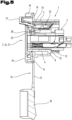
- einen Längsschnitt entsprechend
Fig. 4 , durch einen Einbausteckverbinder derFig. 1 ; - Fig. 6
- eine perspektivische Vorderansicht einer weiteren Ausführungsform eines erfindungsgemässen Einbausteckverbinders;
- Fig. 7
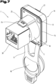
- eine perspektivische Rückansicht des Einbausteckverbinders der
Fig. 6 ; - Fig. 8
- eine Explosionsdarstellung des Einbausteckverbinders der
Fig. 6 ; - Fig. 9
- einen Längsschnitt durch den Einbausteckverbinder der
Fig. 6 in der senkrechten Mittelebene. - Einführend sei festgehalten, dass in den unterschiedlich beschriebenen Ausführungsformen gleiche Teile mit gleichen Bezugszeichen bzw. gleichen Bauteilbezeichnungen versehen werden, wobei die in der gesamten Beschreibung enthaltenen Offenbarungen sinngemäß auf gleiche Teile mit gleichen Bezugszeichen bzw. gleichen Bauteilbezeichnungen übertragen werden können. Auch sind die in der Beschreibung gewählten Lageangaben, wie z.B. oben, unten, seitlich usw. auf die unmittelbar beschriebene sowie dargestellte Figur bezogen und sind diese Lageangaben bei einer Lageänderung sinngemäß auf die neue Lage zu übertragen.
- In den
Fig. 1 bis 5 ist eine erste vorteilhafte Ausführungsform eines erfindungsgemässen Einbausteckverbinders dargestellt, in einer Variante des XLR-Standards mit drei Kontakten, als weiblicher Teil der Steckverbindung bzw. als Einbaubuchse. - Die Einbaubuchse der
Fig. 1 bis 5 als Beispiel für einen elektrischen Steckverbinder gemäss der Erfindung weist ein Gehäuse 1 mit zumindest einer Einstecköffnung 2 für einen komplementären Steckverbinder auf. In diesem Gehäuse 1 ist ein Kontaktträger 3 für die durch dessen Kontakt-Einstecköffnung(en) 4 zugänglichen elektrischen Kontakte. Der Kontaktträger 3 ist für Steckverbindungen gemäss dem XLR-Standard ausgeführt, hier im dargestellten Beispiel mit drei Kontakten. - Das Gehäuse 1 ist aufgebaut aus zwei konzentrisch angeordneten Gehäuseteilen, einem äusseren Gehäuseteil 5 und einem inneren Gehäuseteil 6, die durch einen Ringspalt 7 beabstandet sind, wobei dieser Ringspalt 7 eine ringförmige Einstecköffnung für einen buchsenförmigen Steckerfortsatz eines komplementären Kabelsteckverbinders bildet. Ein ringförmiger Boden 8 verbindet die beiden Gehäuseteile 5, 6 an dem der Einstecköffnung 2 gegenüberliegenden Ende des Gehäuses 1 miteinander. Das zylindrische Volumen im Inneren des innenliegenden Gehäuseteils 6 bildet die Aufnahme 9 für den Kontaktträger 3.
- Am vorderen Ende des Gehäuses 1 ist ein hier beispielhaft mit quadratischem Umriss dargestellter Montageflansch 10 angeordnet, der radial vom Gehäuse 1, insbesondere vom äusseren Gehäuseteil 5, auskragt und in welchem auch Montagebohrungen 11 ausgenommen sein können. Es können auch andere Umrissformen auftreten, beispielsweise kreisförmige oder rechteckige Umrisse. Allenfalls können auch nur eine oder mehrere kleine Montagelaschen an einem sonst allein zylindrisch ausgebildeten Gehäuse 1 angeordnet sein.
- Die Vorderseite des Gehäuses 1 bzw. der Montageflansch 10 können vorteilhafterweise von einer Dichtung 13 abgedeckt sein, welche die Einbausteckerbuchse gegenüber der Wandung abdichtet, in welcher die Buchse eingebaut und fixiert ist. Bevorzug weist die Dichtung 13 einen plattenförmigen Abschnitt 14 auf, welcher den Montageflansch 10 überdeckt, ebenfalls mit Ausnehmung 15 an der Stelle der Montagebohrungen 11 und einer zentralen Ausnehmung 16 zur Durchführung des komplementären Kabelsteckverbinders versehen. Bevorzugt gehen von dem plattenförmigen Abschnitt 14 flexible Streifen 17 aus, an deren Ende ein beispielsweise topfförmiger Dichtstopfen 18 zum Einstecken in die Ausnehmung 16 und vorzugsweise auch den Ringspalt 7 zwischen innerem Gehäuseteil 6 und äusserem Gehäuseteil 5, um die Einbausteckerbuchse bei nicht eingestecktem komplementären Steckverbinder dicht verschliessen zu können.
- Zur Fixierung der Dichtung und für eine bessere mechanische Stabilität der gesamten Anordnung ist vorzugsweise eine Frontplatte 19 vorhanden, welche die Vorderseite des Montageflansches 10 und gegebenenfalls auch die Dichtung 13, insbesondere deren plattenförmigen Abschnitt 14, nach vorne hin abdeckt. Auch diese Frontplatte 19 weist an den Stellen der Montagebohrungen 11 des Montageflansches 10, allenfalls auch den Ausnehmungen 15 der Dichtung 13, eigene Montagebohrungen 20 auf. Auch eine zentrale Ausnehmung als Einstecköffnung 21 ist vorhanden.
- Bevorzugt weist der erfindungsgemässe Steckverbinder auch einen Verriegelungsmechanismus 22 für einen eingesteckten komplementären Steckverbinder auf, um ein ungewolltes Abziehen des Kabelsteckverbinders und damit ein Lösen der Steckverbindung zu verhindern. Dieser Mechanismus 22 umfasst zumindest ein Verriegelungselement 23, welches vorzugsweise am Kontaktträger 3 angeordnet ist. Zur beabsichtigten Entriegelung und Gestattung des Abziehens des Kabelsteckverbinders ist ein Entriegelungselement 24 in Wirkverbindung mit dem Verriegelungselement 23 in den Verriegelungsmechanismus 22 integriert. Das Entriegelungselement 24 ragt, ausgehend vom Verriegelungselement 23, durch Ausnehmungen bzw. Ausstülpungen 25 im Gehäuse 1 und eine radiale Ausnehmung 26 in der zentralen Ausnehmung 21 der Frontplatte 19 auf der Vorderseite des Gehäuses 1 bzw. der Frontplatte 19 heraus, von wo es für den Benutzer zur Betätigung zugänglich ist.
- Um dabei die Dichtwirkung nicht zu beeinträchtigen, ist der durch die Frontplatte 19 ragende Abschnitt des Entriegelungselementes 24 durch einen einstückig an der Dichtung 13, insbesondere am plattenförmigen Abschnitt 14, angeformten Dom 27 zur Aufnahme des Entriegelungselementes 24, welcher Dom 27 nach vorne ragt und vorzugsweise durch die Frontplatte 19 auf deren Vorderseite herausragt.
- Wie in den
Fig. 1 und5 zu erkennen ist, ist der Kontaktträger 3 vorzugsweise als Einschubteil ausgebildet ist und sind gegebenenfalls Führungsstrukturen zwischen der Innenwand des inneren Gehäuseteils 6 und dem Kontaktträger 3 ausgebildet. Vorzugsweise kann auch ein Verbindungsmechanismus zwischen dem Kontaktträger 3 und dem Gehäuse 1 wirken, um den Kontaktträger 3 sicher um Gehäuse 1 zu halten. Allenfalls kann dies durch crimpen des hinteren Randes des Gehäuses 1 radial nach innen über einen äusseren Umfangsrand des eingeschobenen Kontaktträgers 3 erfolgen. Eine andere Alternative besteht darin, dass der Verbindungsmechanismus als Rast- bzw. Schnappverbindung aufgebaut ist. - Der Kontaktträger 3 weist eine Schulter 31 auf, die über einen grossen Teil des Umfanges verläuft und durch eine Durchmesservergrösserung zwischen dem einsteckseitigen Längsabschnitt und dem daran anschliessenden Abschnitt gebildet ist. In komplementärer Weise ist an der Innenseite des Gehäuses 1, etwa in Höhe des Bodens 8, der den inneren Gehäuseteil 6 mit dem äusseren Gehäuseteil 5 verbindet, ein Absatz 32 ausgebildet. An diesem Absatz 32 kommt die Schulter 31 des Kontaktträgers 3 beim Einschieben in das Gehäuse 1 zum Anschlag, wodurch die gewünschte Positionierung der beiden Bauteile relativ zueinander sichergestellt ist.
- Die bei insbesondere XLR Kontaktträgern 3 bestehende Freisparung 34 an der Vorderseite, an welche sich der Bereich der Lagerung für den Verriegelungsmechanismus 22 anschliesst, ist durch eine zur Mitte der Einstecköffnung 2 ragende Nase 28 abgedeckt. Diese kann vorteilhafterweise zwei parallel zur Längsachse des Gehäuses 1 verlaufende Führungen 29 aufweisen, zwischen welchen insbesondere die Feder des Verriegelungsmechanismus 22 geführt und gehalten ist.
- In den
Fig. 6 bis 9 ist eine weitere und gegebenenfalls für sich eigenständige Ausführungsform eines erfindungsgemässen Einbausteckverbinders gezeigt, wobei wiederum für gleiche Teile gleiche Bezugszeichen bzw. Bauteilbezeichnungen wie in den vorangegangenenFig. 1 bis 5 verwendet werden. Um unnötige Wiederholungen zu vermeiden, wird auf die detaillierte Beschreibung der vorangegangenen Abbildungen hingewiesen bzw. Bezug genommen. DieFig. 6 bis 9 zeigen eine Einbaubuchse für einen Datenstecker, insbesondere einen RJ-45 Stecker. - Der Kontaktträger 3 dieser Version der erfindungsgemässen Einbausteckerbuchse ist an der Rückseite des Gehäuses 1 von einer Kontaktdurchführung 29 und einer hinteren Abdeckung 30 abgedeckt und geschützt.
- Die Ausführungsbeispiele zeigen mögliche Ausführungsvarianten, wobei an dieser Stelle bemerkt sei, dass die Erfindung nicht auf die speziell dargestellten Ausführungsvarianten derselben eingeschränkt ist. Der Schutzbereich ist durch die Ansprüche bestimmt.
-
36 1 Gehäuse 37 2 Einstecköffnung 38 3 Kontaktträger 39 4 Einstecköffnungen 40 5 Äusserer Gehäuseteil 6 Innerer Gehäuseteil 41 7 Ringspalt 42 8 Boden 43 9 Aufnahme 44 10 Montageflansch 45 11 Montagebohrungen 46 12 .. 47 13 Dichtung 48 14 Plattenförmiger Abschnitt 49 15 Ausnehmung 50 16 Zentrale Ausnehmung 51 17 Streifen 52 18 Dichtstopfen 53 19 Frontplatte 54 20 Montagebohrung 55 21 Zentrale Ausnehmung 56 22 Verriegelungsmechanismus 57 23 Verriegelungselemente 58 24 Entriegelungselement 59 25 Ausstülpung/Ausnehmung 60 26 Radiale Ausnehmung 61 27 Dom 62 28 Nase 63 29 Kontaktdurchführung 64 30 Abdeckung 65 31 Schulter 32 Absatz 33 Führung 34 Freisparung 35
Claims (11)
- Elektrischer Steckverbinder, mit einem Gehäuse (1) mit zumindest einer Einstecköffnung (2) für einen komplementären Steckverbinder und einem in das Gehäuse (1) eingeschobenen und als Einschubteil ausgebildeten Kontaktträger (3) für die durch die Einstecköffnung(en) zugänglichen elektrischen Kontakte, wobei das Gehäuse (1) zwei konzentrisch angeordnete und sich in Längsrichtung überlappende Gehäuseteile (5, 6) aufweist, wobei ein Boden (8) an dem der zumindest einen Einstecköffnung (2) gegenüberliegenden Ende die Gehäuseteile (5, 6) miteinander verbindet, und wobei ein ringförmiger Zwischenraum (7) zwischen den konzentrischen Gehäuseteilen (5, 6) eine ringförmige Aufnahme für den Steckerfortsatz eines komplementären Steckverbinders bildet, wobei eine Aufnahme (9) für den Kontaktträger (3) im Inneren des inneren Gehäuseteils (6) in Höhe der Überlappung der konzentrischen Gehäuseteile (5, 6) ausgeformt ist und der Kontaktträger (3) sich in den Längsabschnitt des inneren Gehäuseteils (6) hinein erstreckt, der mit dem äusseren Gehäuseteil (5) überlappt, wobei der Steckverbinder weiterhin einen Verriegelungsmechanismus (22) für einen eingesteckten komplementären Steckverbinder, umfassend zumindest ein Verriegelungselement (23), aufweist, wobei der Kontaktträger (3) ausgebildet ist- für Steckverbindungen gemäß dem XLR-Standard, oder- als Buchse für einen RJ45-Stecker.
- Steckverbinder nach Anspruch 1, dadurch gekennzeichnet, dass Führungsstrukturen zwischen der Innenwand des inneren Gehäuseteils (6) und dem Kontaktträger (3) ausgebildet sind.
- Steckverbinder nach Anspruch 1 oder 2, gekennzeichnet durch einen Verbindungsmechanismus zwischen dem Kontaktträger (3) und dem Gehäuse (1).
- Steckverbinder nach Anspruch 3, dadurch gekennzeichnet, dass der Verbindungsmechanismus als Rast- bzw. Schnappverbindung aufgebaut ist.
- Steckverbinder nach einem der Ansprüche 1 bis 4, gekennzeichnet durch zumindest einen Anschlag (32) für den Kontaktträger (3).
- Steckverbinder nach einem der Ansprüche 1 bis 5, gekennzeichnet durch einen radial vom äusseren Gehäuseteil (5) auskragenden Montageflansch (10), der vorzugsweise am einsteckseitigen Ende des äusseren Gehäuseteils (5) positioniert ist.
- Steckverbinder nach Anspruch 6, gekennzeichnet durch eine Dichtung (13), welche eine Vorderseite des Montageflansches (10) abdeckt und zumindest eine der Einstecköffnung (2) entsprechende Ausnehmung (16) aufweist.
- Steckverbinder nach Anspruch 6 oder 7, gekennzeichnet durch eine Frontplatte (19), welche die Vorderseite des Montageflansches (10) und gegebenenfalls auch die Dichtung (13) nach vorne hin abdeckt.
- Steckverbinder nach einem der Ansprüche 1 bis 8, wobei das Verriegelungselement (23) am Kontaktträger (3) angeordnet ist.
- Steckverbinder nach Anspruch 9, gekennzeichnet durch ein Entriegelungselement (24), welches vom Verriegelungselement (23) durch Ausnehmungen im Gehäuse (1) und allenfalls der Frontplatte (19) auf der Vorderseite des Gehäuses (1) bzw. der Frontplatte (19) herausragt.
- Steckverbinder nach Anspruch 7 oder 8 und 10, gekennzeichnet durch eine Dichtung (13) mit einem einstückig angeformten Dom (27) zur Aufnahme des Entriegelungselementes (24), welcher Dom (27) nach vorne ragt und vorzugsweise durch die Frontplatte (19) auf deren Vorderseite herausragt.
Applications Claiming Priority (2)
| Application Number | Priority Date | Filing Date | Title |
|---|---|---|---|
| ATA50815/2019A AT523021B1 (de) | 2019-09-24 | 2019-09-24 | Elektrischer Steckverbinder |
| PCT/EP2020/025424 WO2021058127A1 (de) | 2019-09-24 | 2020-09-21 | Elektrischer steckverbinder |
Publications (2)
| Publication Number | Publication Date |
|---|---|
| EP4035229A1 EP4035229A1 (de) | 2022-08-03 |
| EP4035229B1 true EP4035229B1 (de) | 2024-11-06 |
Family
ID=72615813
Family Applications (1)
| Application Number | Title | Priority Date | Filing Date |
|---|---|---|---|
| EP20776070.3A Active EP4035229B1 (de) | 2019-09-24 | 2020-09-21 | Elektrischer steckverbinder |
Country Status (11)
| Country | Link |
|---|---|
| US (1) | US12184007B2 (de) |
| EP (1) | EP4035229B1 (de) |
| JP (1) | JP7389897B2 (de) |
| KR (1) | KR20220057581A (de) |
| CN (2) | CN114450857A (de) |
| AT (1) | AT523021B1 (de) |
| AU (1) | AU2020356148A1 (de) |
| BR (1) | BR112022004625A2 (de) |
| CA (1) | CA3153981A1 (de) |
| MX (1) | MX2022003126A (de) |
| WO (1) | WO2021058127A1 (de) |
Families Citing this family (3)
| Publication number | Priority date | Publication date | Assignee | Title |
|---|---|---|---|---|
| USD1042358S1 (en) * | 2021-06-18 | 2024-09-17 | Tyco Electronics (Shanghai) Co., Ltd. | Connector housing |
| US12278446B2 (en) | 2021-08-18 | 2025-04-15 | R.A. Phillips Industries, Inc. | Self-sealing electrical plug-and-socket assembly |
| TWI818772B (zh) * | 2022-10-18 | 2023-10-11 | 佳必琪國際股份有限公司 | 儲能連接器 |
Citations (2)
| Publication number | Priority date | Publication date | Assignee | Title |
|---|---|---|---|---|
| EP2908385A1 (de) * | 2012-10-12 | 2015-08-19 | Yazaki Corporation | Ladungseinlassvorrichtung |
| EP3748784A1 (de) * | 2019-06-05 | 2020-12-09 | Delta Plus Co., Ltd. | Elektrischer steckverbinder |
Family Cites Families (17)
| Publication number | Priority date | Publication date | Assignee | Title |
|---|---|---|---|---|
| JP2000348815A (ja) * | 1999-06-03 | 2000-12-15 | Yazaki Corp | 防水コネクタ及び該防水コネクタの組付方法 |
| JP2001052804A (ja) * | 1999-08-03 | 2001-02-23 | Yazaki Corp | 防水コネクタ及び該防水コネクタの組付方法 |
| DE102008004801B4 (de) * | 2007-02-02 | 2011-12-08 | Japan Aviation Electronics Industry, Ltd. | Steckverbinder und damit ausgestattetes Gerät |
| JP4577793B2 (ja) * | 2008-06-04 | 2010-11-10 | ヒロセ電機株式会社 | 防水コネクタ、及び、この防水コネクタを用いた防水装置 |
| CN201498774U (zh) * | 2009-07-23 | 2010-06-02 | 宁波日鼎电子科技有限公司 | 一种大小电流差异导体针的接插件 |
| JP5707808B2 (ja) * | 2010-09-21 | 2015-04-30 | 富士通株式会社 | 結合デバイス |
| CN204615057U (zh) * | 2015-04-17 | 2015-09-02 | 宁波海曙区西尚电子有限公司 | 防水卡侬插座 |
| CN204516967U (zh) | 2015-04-17 | 2015-07-29 | 宁波海曙区西尚电子有限公司 | 直通式双母座网络连接器插座 |
| TWM531675U (zh) * | 2016-03-31 | 2016-11-01 | Advanced Connectek Inc | 防水襯套連接器組件、防水襯套插座連接器以及防水襯套插頭連接器 |
| EP3252876B1 (de) * | 2016-06-01 | 2019-05-01 | Aptiv Technologies Limited | Elektrischer stecker mit kodierfunktion |
| JP6769353B2 (ja) * | 2017-03-13 | 2020-10-14 | 株式会社オートネットワーク技術研究所 | 端子ユニット及びコネクタ |
| JP6840583B2 (ja) * | 2017-03-16 | 2021-03-10 | モレックス エルエルシー | コネクタアッセンブリ及びコネクタカバー |
| DE102017003149A1 (de) * | 2017-03-31 | 2018-10-04 | Yamaichi Electronics Deutschland Gmbh | Dichtvorrichtung, Verfahren und Verwendung |
| CN207009841U (zh) * | 2017-06-12 | 2018-02-13 | 西安丰石电子科技有限公司 | 一种插针式射频同轴连接器 |
| CN110031693A (zh) * | 2018-01-12 | 2019-07-19 | 康普技术有限责任公司 | 用于测试同轴连接器的无源互调的测试工装和方法 |
| CN109273904A (zh) * | 2018-10-17 | 2019-01-25 | 德尔特微波电子(南京)有限公司 | 一种旋拧式射频同轴连接器 |
| AT522949B1 (de) * | 2019-09-24 | 2021-05-15 | Neutrik Ag | Dichtung |
-
2019
- 2019-09-24 AT ATA50815/2019A patent/AT523021B1/de not_active IP Right Cessation
-
2020
- 2020-09-21 EP EP20776070.3A patent/EP4035229B1/de active Active
- 2020-09-21 BR BR112022004625A patent/BR112022004625A2/pt not_active Application Discontinuation
- 2020-09-21 AU AU2020356148A patent/AU2020356148A1/en not_active Abandoned
- 2020-09-21 MX MX2022003126A patent/MX2022003126A/es unknown
- 2020-09-21 JP JP2022518992A patent/JP7389897B2/ja active Active
- 2020-09-21 CN CN202080067438.5A patent/CN114450857A/zh active Pending
- 2020-09-21 KR KR1020227011076A patent/KR20220057581A/ko not_active Ceased
- 2020-09-21 WO PCT/EP2020/025424 patent/WO2021058127A1/de not_active Ceased
- 2020-09-21 CA CA3153981A patent/CA3153981A1/en not_active Abandoned
- 2020-09-21 US US17/763,115 patent/US12184007B2/en active Active
- 2020-09-21 CN CN202510209146.5A patent/CN119994537A/zh active Pending
Patent Citations (2)
| Publication number | Priority date | Publication date | Assignee | Title |
|---|---|---|---|---|
| EP2908385A1 (de) * | 2012-10-12 | 2015-08-19 | Yazaki Corporation | Ladungseinlassvorrichtung |
| EP3748784A1 (de) * | 2019-06-05 | 2020-12-09 | Delta Plus Co., Ltd. | Elektrischer steckverbinder |
Also Published As
| Publication number | Publication date |
|---|---|
| US12184007B2 (en) | 2024-12-31 |
| CN119994537A (zh) | 2025-05-13 |
| MX2022003126A (es) | 2022-04-06 |
| AT523021B1 (de) | 2023-03-15 |
| KR20220057581A (ko) | 2022-05-09 |
| AT523021A1 (de) | 2021-04-15 |
| AU2020356148A1 (en) | 2022-04-14 |
| BR112022004625A2 (pt) | 2022-05-31 |
| WO2021058127A1 (de) | 2021-04-01 |
| CN114450857A (zh) | 2022-05-06 |
| US20220344865A1 (en) | 2022-10-27 |
| EP4035229A1 (de) | 2022-08-03 |
| JP7389897B2 (ja) | 2023-11-30 |
| CA3153981A1 (en) | 2021-04-01 |
| JP2022550318A (ja) | 2022-12-01 |
Similar Documents
| Publication | Publication Date | Title |
|---|---|---|
| EP4035229B1 (de) | Elektrischer steckverbinder | |
| DE68920106T2 (de) | Elektrischer Verbinder. | |
| DE102008022916A1 (de) | Elektromotor | |
| DE112015000653T5 (de) | Elektrische Verbinderanordnung | |
| DE102018207600A1 (de) | Dichtungs-Anordnungs-Struktur | |
| EP3787128B1 (de) | Steckverbindung | |
| EP0203404A2 (de) | Vorrichtung zur Verbindung von Schirmungskappen mehrpoliger Stecker mit der Erdpotentialschicht einer Verdrahtungsplatte | |
| EP1867010B1 (de) | Berührungssichere steckverbindung, insbesondere solarsteckverbindung | |
| AT523019B1 (de) | Elektrischer Steckverbinder | |
| EP2551978B1 (de) | Vorrichtung zur Durchführung einer elektrischen Leitung durch ein Gehäuse | |
| EP2417674B1 (de) | Steckverbindungsvorrichtung | |
| DE102021128761A1 (de) | Bidirektionales Kopfstück zum Zusammenstecken von Verbindern in mehreren Richtungen | |
| EP1776738B1 (de) | Anschlussvorrichtung für einen elektromotor | |
| EP4292173B1 (de) | Einsatz für einen verbinder | |
| DE102014012739B4 (de) | Elektrischer Steckverbinder, Verbinderelement und Verwendung | |
| DE202012101303U1 (de) | Steckverbindergehäuse | |
| WO2017036453A1 (de) | Kontaktträger | |
| BE1025487B1 (de) | Elektrischer steckverbinder zur ausbildung eines leiterplattensteckverbinders an einer leiterplatte | |
| DE3513504C2 (de) | ||
| EP4231463B1 (de) | Steckverbinder zur montage auf einer leiterplatte | |
| EP0319459B1 (de) | Steckverbindung für Koaxialleiter, insbesondere für Antennen | |
| EP0834960A2 (de) | Steckdose | |
| DE19817308C2 (de) | Abdeckung für ein in eine Wand eingebautes elektrisches Installationsgerät | |
| DE202008015055U1 (de) | Elektrische Kupplungsvorrichtung | |
| DE19544361B4 (de) | Abschirmung für einen elektrischen Stecker und abgeschirmter elektrischer Stecker |
Legal Events
| Date | Code | Title | Description |
|---|---|---|---|
| STAA | Information on the status of an ep patent application or granted ep patent |
Free format text: STATUS: UNKNOWN |
|
| STAA | Information on the status of an ep patent application or granted ep patent |
Free format text: STATUS: THE INTERNATIONAL PUBLICATION HAS BEEN MADE |
|
| PUAI | Public reference made under article 153(3) epc to a published international application that has entered the european phase |
Free format text: ORIGINAL CODE: 0009012 |
|
| STAA | Information on the status of an ep patent application or granted ep patent |
Free format text: STATUS: REQUEST FOR EXAMINATION WAS MADE |
|
| 17P | Request for examination filed |
Effective date: 20220321 |
|
| AK | Designated contracting states |
Kind code of ref document: A1 Designated state(s): AL AT BE BG CH CY CZ DE DK EE ES FI FR GB GR HR HU IE IS IT LI LT LU LV MC MK MT NL NO PL PT RO RS SE SI SK SM TR |
|
| DAV | Request for validation of the european patent (deleted) | ||
| DAX | Request for extension of the european patent (deleted) | ||
| GRAP | Despatch of communication of intention to grant a patent |
Free format text: ORIGINAL CODE: EPIDOSNIGR1 |
|
| STAA | Information on the status of an ep patent application or granted ep patent |
Free format text: STATUS: GRANT OF PATENT IS INTENDED |
|
| INTG | Intention to grant announced |
Effective date: 20240618 |
|
| GRAS | Grant fee paid |
Free format text: ORIGINAL CODE: EPIDOSNIGR3 |
|
| GRAA | (expected) grant |
Free format text: ORIGINAL CODE: 0009210 |
|
| STAA | Information on the status of an ep patent application or granted ep patent |
Free format text: STATUS: THE PATENT HAS BEEN GRANTED |
|
| AK | Designated contracting states |
Kind code of ref document: B1 Designated state(s): AL AT BE BG CH CY CZ DE DK EE ES FI FR GB GR HR HU IE IS IT LI LT LU LV MC MK MT NL NO PL PT RO RS SE SI SK SM TR |
|
| REG | Reference to a national code |
Ref country code: GB Ref legal event code: FG4D Free format text: NOT ENGLISH |
|
| REG | Reference to a national code |
Ref country code: CH Ref legal event code: EP |
|
| REG | Reference to a national code |
Ref country code: DE Ref legal event code: R096 Ref document number: 502020009710 Country of ref document: DE |
|
| REG | Reference to a national code |
Ref country code: IE Ref legal event code: FG4D Free format text: LANGUAGE OF EP DOCUMENT: GERMAN |
|
| REG | Reference to a national code |
Ref country code: LT Ref legal event code: MG9D |
|
| REG | Reference to a national code |
Ref country code: NL Ref legal event code: MP Effective date: 20241106 |
|
| PG25 | Lapsed in a contracting state [announced via postgrant information from national office to epo] |
Ref country code: PT Free format text: LAPSE BECAUSE OF FAILURE TO SUBMIT A TRANSLATION OF THE DESCRIPTION OR TO PAY THE FEE WITHIN THE PRESCRIBED TIME-LIMIT Effective date: 20250306 Ref country code: HR Free format text: LAPSE BECAUSE OF FAILURE TO SUBMIT A TRANSLATION OF THE DESCRIPTION OR TO PAY THE FEE WITHIN THE PRESCRIBED TIME-LIMIT Effective date: 20241106 Ref country code: IS Free format text: LAPSE BECAUSE OF FAILURE TO SUBMIT A TRANSLATION OF THE DESCRIPTION OR TO PAY THE FEE WITHIN THE PRESCRIBED TIME-LIMIT Effective date: 20250306 |
|
| PG25 | Lapsed in a contracting state [announced via postgrant information from national office to epo] |
Ref country code: NL Free format text: LAPSE BECAUSE OF FAILURE TO SUBMIT A TRANSLATION OF THE DESCRIPTION OR TO PAY THE FEE WITHIN THE PRESCRIBED TIME-LIMIT Effective date: 20241106 Ref country code: FI Free format text: LAPSE BECAUSE OF FAILURE TO SUBMIT A TRANSLATION OF THE DESCRIPTION OR TO PAY THE FEE WITHIN THE PRESCRIBED TIME-LIMIT Effective date: 20241106 |
|
| PG25 | Lapsed in a contracting state [announced via postgrant information from national office to epo] |
Ref country code: BG Free format text: LAPSE BECAUSE OF FAILURE TO SUBMIT A TRANSLATION OF THE DESCRIPTION OR TO PAY THE FEE WITHIN THE PRESCRIBED TIME-LIMIT Effective date: 20241106 |
|
| PG25 | Lapsed in a contracting state [announced via postgrant information from national office to epo] |
Ref country code: ES Free format text: LAPSE BECAUSE OF FAILURE TO SUBMIT A TRANSLATION OF THE DESCRIPTION OR TO PAY THE FEE WITHIN THE PRESCRIBED TIME-LIMIT Effective date: 20241106 |
|
| PG25 | Lapsed in a contracting state [announced via postgrant information from national office to epo] |
Ref country code: NO Free format text: LAPSE BECAUSE OF FAILURE TO SUBMIT A TRANSLATION OF THE DESCRIPTION OR TO PAY THE FEE WITHIN THE PRESCRIBED TIME-LIMIT Effective date: 20250206 |
|
| PG25 | Lapsed in a contracting state [announced via postgrant information from national office to epo] |
Ref country code: GR Free format text: LAPSE BECAUSE OF FAILURE TO SUBMIT A TRANSLATION OF THE DESCRIPTION OR TO PAY THE FEE WITHIN THE PRESCRIBED TIME-LIMIT Effective date: 20250207 Ref country code: LV Free format text: LAPSE BECAUSE OF FAILURE TO SUBMIT A TRANSLATION OF THE DESCRIPTION OR TO PAY THE FEE WITHIN THE PRESCRIBED TIME-LIMIT Effective date: 20241106 |
|
| PG25 | Lapsed in a contracting state [announced via postgrant information from national office to epo] |
Ref country code: PL Free format text: LAPSE BECAUSE OF FAILURE TO SUBMIT A TRANSLATION OF THE DESCRIPTION OR TO PAY THE FEE WITHIN THE PRESCRIBED TIME-LIMIT Effective date: 20241106 |
|
| PG25 | Lapsed in a contracting state [announced via postgrant information from national office to epo] |
Ref country code: RS Free format text: LAPSE BECAUSE OF FAILURE TO SUBMIT A TRANSLATION OF THE DESCRIPTION OR TO PAY THE FEE WITHIN THE PRESCRIBED TIME-LIMIT Effective date: 20250206 |
|
| PG25 | Lapsed in a contracting state [announced via postgrant information from national office to epo] |
Ref country code: SM Free format text: LAPSE BECAUSE OF FAILURE TO SUBMIT A TRANSLATION OF THE DESCRIPTION OR TO PAY THE FEE WITHIN THE PRESCRIBED TIME-LIMIT Effective date: 20241106 |
|
| PG25 | Lapsed in a contracting state [announced via postgrant information from national office to epo] |
Ref country code: DK Free format text: LAPSE BECAUSE OF FAILURE TO SUBMIT A TRANSLATION OF THE DESCRIPTION OR TO PAY THE FEE WITHIN THE PRESCRIBED TIME-LIMIT Effective date: 20241106 |
|
| PG25 | Lapsed in a contracting state [announced via postgrant information from national office to epo] |
Ref country code: EE Free format text: LAPSE BECAUSE OF FAILURE TO SUBMIT A TRANSLATION OF THE DESCRIPTION OR TO PAY THE FEE WITHIN THE PRESCRIBED TIME-LIMIT Effective date: 20241106 |
|
| PG25 | Lapsed in a contracting state [announced via postgrant information from national office to epo] |
Ref country code: RO Free format text: LAPSE BECAUSE OF FAILURE TO SUBMIT A TRANSLATION OF THE DESCRIPTION OR TO PAY THE FEE WITHIN THE PRESCRIBED TIME-LIMIT Effective date: 20241106 |
|
| PG25 | Lapsed in a contracting state [announced via postgrant information from national office to epo] |
Ref country code: SK Free format text: LAPSE BECAUSE OF FAILURE TO SUBMIT A TRANSLATION OF THE DESCRIPTION OR TO PAY THE FEE WITHIN THE PRESCRIBED TIME-LIMIT Effective date: 20241106 |
|
| PG25 | Lapsed in a contracting state [announced via postgrant information from national office to epo] |
Ref country code: CZ Free format text: LAPSE BECAUSE OF FAILURE TO SUBMIT A TRANSLATION OF THE DESCRIPTION OR TO PAY THE FEE WITHIN THE PRESCRIBED TIME-LIMIT Effective date: 20241106 |
|
| PG25 | Lapsed in a contracting state [announced via postgrant information from national office to epo] |
Ref country code: IT Free format text: LAPSE BECAUSE OF FAILURE TO SUBMIT A TRANSLATION OF THE DESCRIPTION OR TO PAY THE FEE WITHIN THE PRESCRIBED TIME-LIMIT Effective date: 20241106 |
|
| REG | Reference to a national code |
Ref country code: DE Ref legal event code: R097 Ref document number: 502020009710 Country of ref document: DE |
|
| PG25 | Lapsed in a contracting state [announced via postgrant information from national office to epo] |
Ref country code: SE Free format text: LAPSE BECAUSE OF FAILURE TO SUBMIT A TRANSLATION OF THE DESCRIPTION OR TO PAY THE FEE WITHIN THE PRESCRIBED TIME-LIMIT Effective date: 20241106 |
|
| PLBE | No opposition filed within time limit |
Free format text: ORIGINAL CODE: 0009261 |
|
| STAA | Information on the status of an ep patent application or granted ep patent |
Free format text: STATUS: NO OPPOSITION FILED WITHIN TIME LIMIT |
|
| PGFP | Annual fee paid to national office [announced via postgrant information from national office to epo] |
Ref country code: DE Payment date: 20250919 Year of fee payment: 6 |
|
| 26N | No opposition filed |
Effective date: 20250807 |
|
| PGFP | Annual fee paid to national office [announced via postgrant information from national office to epo] |
Ref country code: GB Payment date: 20250919 Year of fee payment: 6 |