EP4035765A1 - Luftdiffusor - Google Patents
Luftdiffusor Download PDFInfo
- Publication number
- EP4035765A1 EP4035765A1 EP20869566.8A EP20869566A EP4035765A1 EP 4035765 A1 EP4035765 A1 EP 4035765A1 EP 20869566 A EP20869566 A EP 20869566A EP 4035765 A1 EP4035765 A1 EP 4035765A1
- Authority
- EP
- European Patent Office
- Prior art keywords
- air
- air diffusion
- water
- width
- tank
- Prior art date
- Legal status (The legal status is an assumption and is not a legal conclusion. Google has not performed a legal analysis and makes no representation as to the accuracy of the status listed.)
- Pending
Links
Images









Classifications
-
- B—PERFORMING OPERATIONS; TRANSPORTING
- B01—PHYSICAL OR CHEMICAL PROCESSES OR APPARATUS IN GENERAL
- B01F—MIXING, e.g. DISSOLVING, EMULSIFYING OR DISPERSING
- B01F23/00—Mixing according to the phases to be mixed, e.g. dispersing or emulsifying
- B01F23/20—Mixing gases with liquids
- B01F23/23—Mixing gases with liquids by introducing gases into liquid media, e.g. for producing aerated liquids
- B01F23/231—Mixing gases with liquids by introducing gases into liquid media, e.g. for producing aerated liquids by bubbling
- B01F23/23105—Arrangement or manipulation of the gas bubbling devices
- B01F23/2312—Diffusers
- B01F23/23123—Diffusers consisting of rigid porous or perforated material
- B01F23/231231—Diffusers consisting of rigid porous or perforated material the outlets being in the form of perforations
-
- B—PERFORMING OPERATIONS; TRANSPORTING
- B01—PHYSICAL OR CHEMICAL PROCESSES OR APPARATUS IN GENERAL
- B01F—MIXING, e.g. DISSOLVING, EMULSIFYING OR DISPERSING
- B01F23/00—Mixing according to the phases to be mixed, e.g. dispersing or emulsifying
- B01F23/20—Mixing gases with liquids
- B01F23/23—Mixing gases with liquids by introducing gases into liquid media, e.g. for producing aerated liquids
- B01F23/231—Mixing gases with liquids by introducing gases into liquid media, e.g. for producing aerated liquids by bubbling
- B01F23/23105—Arrangement or manipulation of the gas bubbling devices
- B01F23/2312—Diffusers
-
- C—CHEMISTRY; METALLURGY
- C02—TREATMENT OF WATER, WASTE WATER, SEWAGE, OR SLUDGE
- C02F—TREATMENT OF WATER, WASTE WATER, SEWAGE, OR SLUDGE
- C02F3/00—Biological treatment of water, waste water, or sewage
- C02F3/02—Aerobic processes
-
- B—PERFORMING OPERATIONS; TRANSPORTING
- B01—PHYSICAL OR CHEMICAL PROCESSES OR APPARATUS IN GENERAL
- B01F—MIXING, e.g. DISSOLVING, EMULSIFYING OR DISPERSING
- B01F23/00—Mixing according to the phases to be mixed, e.g. dispersing or emulsifying
- B01F23/20—Mixing gases with liquids
- B01F23/23—Mixing gases with liquids by introducing gases into liquid media, e.g. for producing aerated liquids
- B01F23/231—Mixing gases with liquids by introducing gases into liquid media, e.g. for producing aerated liquids by bubbling
- B01F23/23105—Arrangement or manipulation of the gas bubbling devices
- B01F23/2312—Diffusers
- B01F23/23126—Diffusers characterised by the shape of the diffuser element
- B01F23/231264—Diffusers characterised by the shape of the diffuser element being in the form of plates, flat beams, flat membranes or films
-
- C—CHEMISTRY; METALLURGY
- C02—TREATMENT OF WATER, WASTE WATER, SEWAGE, OR SLUDGE
- C02F—TREATMENT OF WATER, WASTE WATER, SEWAGE, OR SLUDGE
- C02F3/00—Biological treatment of water, waste water, or sewage
- C02F3/02—Aerobic processes
- C02F3/12—Activated sludge processes
- C02F3/20—Activated sludge processes using diffusers
-
- C—CHEMISTRY; METALLURGY
- C02—TREATMENT OF WATER, WASTE WATER, SEWAGE, OR SLUDGE
- C02F—TREATMENT OF WATER, WASTE WATER, SEWAGE, OR SLUDGE
- C02F3/00—Biological treatment of water, waste water, or sewage
- C02F3/02—Aerobic processes
- C02F3/12—Activated sludge processes
- C02F3/20—Activated sludge processes using diffusers
- C02F3/201—Perforated, resilient plastic diffusers, e.g. membranes, sheets, foils, tubes, hoses
-
- B—PERFORMING OPERATIONS; TRANSPORTING
- B01—PHYSICAL OR CHEMICAL PROCESSES OR APPARATUS IN GENERAL
- B01F—MIXING, e.g. DISSOLVING, EMULSIFYING OR DISPERSING
- B01F2101/00—Mixing characterised by the nature of the mixed materials or by the application field
- B01F2101/305—Treatment of water, waste water or sewage
-
- B—PERFORMING OPERATIONS; TRANSPORTING
- B01—PHYSICAL OR CHEMICAL PROCESSES OR APPARATUS IN GENERAL
- B01F—MIXING, e.g. DISSOLVING, EMULSIFYING OR DISPERSING
- B01F2215/00—Auxiliary or complementary information in relation with mixing
- B01F2215/04—Technical information in relation with mixing
- B01F2215/0409—Relationships between different variables defining features or parameters of the apparatus or process
-
- B—PERFORMING OPERATIONS; TRANSPORTING
- B01—PHYSICAL OR CHEMICAL PROCESSES OR APPARATUS IN GENERAL
- B01F—MIXING, e.g. DISSOLVING, EMULSIFYING OR DISPERSING
- B01F2215/00—Auxiliary or complementary information in relation with mixing
- B01F2215/04—Technical information in relation with mixing
- B01F2215/0413—Numerical information
- B01F2215/0418—Geometrical information
- B01F2215/0431—Numerical size values, e.g. diameter of a hole or conduit, area, volume, length, width, or ratios thereof
-
- C—CHEMISTRY; METALLURGY
- C02—TREATMENT OF WATER, WASTE WATER, SEWAGE, OR SLUDGE
- C02F—TREATMENT OF WATER, WASTE WATER, SEWAGE, OR SLUDGE
- C02F2201/00—Apparatus for treatment of water, waste water or sewage
- C02F2201/002—Construction details of the apparatus
-
- C—CHEMISTRY; METALLURGY
- C02—TREATMENT OF WATER, WASTE WATER, SEWAGE, OR SLUDGE
- C02F—TREATMENT OF WATER, WASTE WATER, SEWAGE, OR SLUDGE
- C02F2203/00—Apparatus and plants for the biological treatment of water, waste water or sewage
- C02F2203/006—Apparatus and plants for the biological treatment of water, waste water or sewage details of construction, e.g. specially adapted seals, modules, connections
-
- C—CHEMISTRY; METALLURGY
- C02—TREATMENT OF WATER, WASTE WATER, SEWAGE, OR SLUDGE
- C02F—TREATMENT OF WATER, WASTE WATER, SEWAGE, OR SLUDGE
- C02F2303/00—Specific treatment goals
- C02F2303/22—Eliminating or preventing deposits, scale removal, scale prevention
-
- Y—GENERAL TAGGING OF NEW TECHNOLOGICAL DEVELOPMENTS; GENERAL TAGGING OF CROSS-SECTIONAL TECHNOLOGIES SPANNING OVER SEVERAL SECTIONS OF THE IPC; TECHNICAL SUBJECTS COVERED BY FORMER USPC CROSS-REFERENCE ART COLLECTIONS [XRACs] AND DIGESTS
- Y02—TECHNOLOGIES OR APPLICATIONS FOR MITIGATION OR ADAPTATION AGAINST CLIMATE CHANGE
- Y02W—CLIMATE CHANGE MITIGATION TECHNOLOGIES RELATED TO WASTEWATER TREATMENT OR WASTE MANAGEMENT
- Y02W10/00—Technologies for wastewater treatment
- Y02W10/10—Biological treatment of water, waste water, or sewage
Definitions
- the present invention relates to an air diffuser configured to feed gas such as air into water.
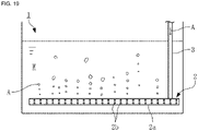
- Fig. 19 illustrates an example of such an aeration tank.
- Water W to be treated is filled in a tank 1, and an air diffuser 2 is installed near a bottom part in the tank 1.
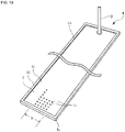
- the air diffuser 2 is a device having, for example, a form illustrated in Fig. 20 , and gas (in this case, air) A is fed into a hollow main body 2a through an air guiding pipe 3 connected to one end of the main body 2a.
- the main body 2a is a pipe having an internal space and arranged with, on side surfaces, a large number of air diffusion holes 2b communicated to inside and outside.
- the air A fed into the main body 2a through the air guiding pipe 3 is discharged as air bubbles to the water W through the air diffusion holes 2b.
- the air A is made contact with the water W to dissolve oxygen into the water W, and the water W filled in the tank 1 is agitated by motion of the air bubbles so that the dissolved oxygen is globally supplied in the tank 1.
- An air diffuser as described above is not limited to a wastewater treatment facility and the like but is generally used at a facility where an organism lives in water filled in a tank, and it is desirable to efficiently supply oxygen with less energy at such a facility as well.
- a gas component other than oxygen such as carbon dioxide
- the efficiency of gas supply is as high as possible.
- the present invention is achieved in consideration of the above-described problem and intended to provide an air diffuser capable of efficiently supplying gas to water.
- the present invention relates to an air diffuser including: a bottom panel provided in a horizontal direction in a tank in which water is filled; an air diffusion body installed to cover the bottom panel from above; and air diffusion holes arranged to penetrate through the air diffusion body, gas fed to a gap between the bottom panel and the air diffusion body is discharged into water through the air diffusion holes, and an air diffusion region of the air diffusion body where the air diffusion holes are arranged has a width equal to or larger than 10 mm and smaller than 120 mm.
- the air diffusion holes may be arranged in an entire range of the air diffusion body in a width direction.
- the air diffusion holes may be arranged in a partial region of the air diffusion body in a width direction.
- the air diffuser of the present invention it is possible to achieve an excellent effect that gas can be efficiently supplied to water.
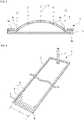
- FIGs. 1 to 4 illustrate an exemplary form of an air diffuser according to an embodiment of the present invention.
- an air diffuser 4 according to the present first example is installed near a bottom part in a tank 1 and feeds air A supplied from an air guiding pipe 3 to water W filled in the tank 1.
- the air diffuser 4 has a rectangular main body 4a.
- the main body 4a includes a bottom panel 4b provided in the horizontal direction in the tank 1 and serving as a bottom surface of the main body 4a, and an air diffusion body 4c installed to cover the bottom panel 4b from above.
- the bottom panel 4b is formed of a hard material such as stainless steel, and the air diffusion body 4c is formed as a soft film.
- a frame 4d is provided on the upper surfaces of four sides of the bottom panel 4b, and the air diffusion body 4c is held to the bottom panel 4b with the four sides sandwiched between the bottom panel 4b and the frame 4d.
- the air diffusion body 4c in a film shape is arranged with a large number of air diffusion holes 4e penetrating through the air diffusion body 4c thereof in the entire range of the air diffusion body 4c in the width direction.
- the air guiding pipe 3 is connected to an end part of the air diffusion body 4c in the longitudinal direction so that the air A is fed from the air guiding pipe 3 to the gap between the air diffusion body 4c and the bottom panel 4b.
- FIG. 3 illustrates only some of the air diffusion holes 4e.
- the air diffusion holes 4e in Figs. 3 and 4 are schematically illustrated, and for example, the hole diameter and interval of actual air diffusion holes 4e as well as the thickness of the air diffusion body 4c may be changed as appropriate in accordance with various conditions when the invention is achieved (this is same for Figs. 5, 6 , and 10 ).
- the pressure of the air A deforms and inflates the air diffusion body 4c upward and the air A between the air diffusion body 4c and the bottom panel 4b is discharged through the air diffusion holes 4e.
- the pressure of the water makes the air diffusion body 4c closely contact with the bottom panel 4b and the air diffusion holes 4e are closed.
- the air A is discharged in the form of air bubbles into the water W through the air diffusion holes 4e, and in a case of non-use, the air diffusion holes 4e are closed to prevent the water W from entering inside, thereby preventing clogging by solid matters inside the main body 4a.
- the clogging can be removed by repeating supply and stop of the air A so that any solid matter is pressed out of the air diffusion holes 4e by deformation of the air diffusion body 4c and the pressure of the air A.
- the width of a range (hereinafter referred to as an air diffusion region R) of the air diffusion body 4c where the air diffusion holes 4e are arranged in other words, the dimension (illustrated as a width D in Fig. 3 ; the value of the width D described below is a dimension in a state in which the air diffusion body 4c is in close contact with the bottom panel 4b) of the range in the transverse direction is preferably equal to or larger than 10 mm and smaller than 120 mm as described later, but is 60 mm in the present first example.
- the length of the main body 4a in other words, the dimension (illustrated as a length L in Fig. 3 ) of the main body 4a in the longitudinal direction may be changed as appropriate in accordance with a condition such as the size of an installation place and is, for example, 0.5 m to 4 m approximately.
- FIG. 6 illustrates, as a reference example of the present invention, the air diffuser 4 in which the width D of the air diffusion region R is set to be 120 mm
- Figs. 7 and 8 correspond to the air diffuser 4 according to the reference example illustrated in Fig. 6 and the air diffuser 4 according to the first example illustrated in Figs. 2 to 5 , respectively, and schematically illustrate motion of the air A and the water W in operation.
- the area of the air diffusion region R is same between the reference example (refer to Fig. 7 ) including only one air diffuser 4 in which the width D of the air diffusion region R (refer to Figs. 3 and 6 ) is 120 mm and the first example (refer to Fig. 8 ) including two air diffusers 4 in which the width D is 60 mm (the above-described numbers of air diffusers 4 per tank 1 are set for convenience of description, but in the actual tank 1, as illustrated in, for example, Fig. 2 , the number of air diffusers 4 installed per tank 1 is typically larger than the numbers illustrated in Figs. 7 and 8 ).
- a larger amount of oxygen can be dissolved into the water W in the first example than in the reference example.
- the tank 1 used in the experiment had a cylindrical shape having an inner diameter of 774 mm and was filled with the water W to the depth of 5.1 m, and a plurality of air diffusers 4 were installed near a bottom surface of the tank 1 (at the water depth of 5.0 m).
- a full floor coverage arrangement was employed in which the air diffusers 4 were equally disposed on the bottom surface of the tank 1 as illustrated in Fig. 2 , and the air A was supplied to each air diffuser 4.
- the length L (refer to Fig. 3 ) was set to be 600 mm
- the length (dimension in a direction orthogonal to the width D) of the air diffusion region R was set to be 400 mm.
- each air diffusion region R differs depending on a condition, and thus the number of installed air diffusers was adjusted to equalize the total area of air diffusion regions R occupying the tank 1 even when the width D of the air diffusion region R in each air diffuser 4 is different.
- the ratio of the total area of air diffusion regions R relative to the bottom area of the tank 1 was set to be 12.8%.
- the horizontal axis represents an air-sending volume (total air flow rate [Nm3/(m2 ⁇ hr)] to each air diffuser 4 per unit time and per unit projection area in the air diffusion body 4c
- the vertical axis represents a relative value (relative value when the efficiency of oxygen solubility for the width D of 150 mm is taken as one) of the efficiency of oxygen solubility for each condition.
- the width D was set to be (37.5 mm, 50 mm, and 75 mm) smaller than 120 mm, the efficiency of oxygen solubility significantly improved (about 1.1 to 1.25 times higher) as compared to a case of the width D of 150 mm, which exceeds 120 mm, and the efficiency of oxygen solubility was higher as the width D was smaller.
- Fig. 10 illustrates an air diffuser 4 according to a second example of the present invention.
- the dimensions of the bottom panel 4b, the frame 4d, and the entire air diffusion body 4c are same as those in the reference example illustrated in Fig. 6 , but the air diffusion holes 4e are arranged only in a central region of the air diffusion body 4c in the width direction.
- the overall dimensions are same as those in the reference example, but the width D of the air diffusion region R is 60 mm, which is same as in the first example.
- the air diffusion holes 4e are arranged at the center of the air diffusion body 4c in the width direction, positions at which the air diffusion holes 4e are arranged are not limited to the center, and the air diffusion holes 4e may be arranged in a partial region in the width direction.
- the positions may be at both end parts in the width direction or near one edge.
- Fig. 11 illustrates a result of an experiment performed to test the efficiency of oxygen solubility in the water W for each of the air diffusers 4 according to the reference example (refer to Fig. 7 ) and the second example (refer to Fig. 10 ).
- the tank 1 used in the experiment had a bottom surface having an internal dimension of 5 m ⁇ 5 m and was filled with the water W at the depth of 5.1 m, and a plurality of air diffusers 4 were installed near (at the water depth of 5.0 m) the bottom surface.
- the air A was supplied to the air diffusers 4 by the full floor coverage arrangement in which the air diffusers 4 were equally disposed on the bottom surface of the tank 1.
- the length of the air diffusion region R in each air diffuser 4 was set to be 2 m.
- the number of installed air diffusers was adjusted to equalize the total area of air diffusion regions R occupying the tank 1 even when the width D of the air diffusion region R in each air diffuser 4 is different.
- the ratio of the total area of air diffusion regions R relative to the bottom area of the tank 1 was set to be 11.5%.
- the horizontal axis represents the total air flow rate [Nm3/(m2 ⁇ hr)] to each air diffuser 4 per unit time and per unit projection area in the air diffusion body 4c
- the vertical axis represents a relative value (relative value when the efficiency of oxygen solubility in the reference example for the same air-sending volume is taken as one) of the efficiency of oxygen solubility
- each triangular symbol represents the reference example
- each circular symbol represents the second example.
- the efficiency of oxygen solubility in the second example is about 1.04 to 1.1 times higher than that in the reference example for each condition.
- the supply amount of the air A per air diffuser 4 is smaller than in the reference example ( Fig. 7 ) (when the total supply amount is 2Qa, the supply amount per air diffuser 4 is 2Qa in the reference example and Qa in the second example), and accordingly, buoyant force applied to an air bubble is small and the ascending speed of the air bubble is slow.
- the water W circulates as illustrated with black arrows in Figs. 7 and 8 along with ascending of air bubbles. Specifically, the water W ascends along with ascending of air bubbles (illustrated with a white arrow) above each air diffuser 4, reverses near the water surface, descends at a position separated from the air diffuser 4 in the width direction, reverses again when having approached the air diffuser 4, and ascends together with air bubbles.
- the ascending speed of air bubbles near the air diffuser 4 is slow, motion of the water W in this region is slow, and in particular, a speed component (illustrated as Vh in Figs. 7 and 8 ) in the horizontal direction toward the air diffuser 4 decreases.
- Motion of the water W toward the air diffuser 4 acts to move closer air bubbles discharged from the air diffuser 4, and thus when the speed of the water W is slow, air bubbles are less likely to coalesce and become integrated and larger, and accordingly, the air bubble diameter decreases.
- the air bubble diameter is small, the ascending speed is slow as described above, and thus the speed of the water W further decreases. Consequently, it is presumed that a positive feedback relation exits between decrease of the ascending speed of air bubbles and reduction of the size of air bubbles.
- the efficiency of oxygen solubility is high when air bubbles discharged from the air diffuser 4 are distributed as much as possible in a wide range without concentrating in a narrow region in the tank 1.
- motion of the water W approaching the air diffuser 4 acts to gather air bubbles discharged from the air diffuser 4.
- the distribution range of air bubbles in the tank 1 increases as the speed component Vh in the horizontal direction decreases.
- the ratio (wa/D; hereinafter referred to as diffusion ratio of air bubbles) of the width (illustrated as wa in Figs. 7 and 8 ) of the distribution range of air bubbles at a height above the air diffuser 4 relative to the width D of the air diffusion region R is higher in the second example than in the reference example.
- Fig. 12 illustrates a result of an experiment performed to test the width of the distribution range of air bubbles.
- the air A in the total amount of 10 N/m 3 or 40 N/m 3 per projection area 1 m 2 in the air diffusion body 4c was supplied to each of the air diffuser 4 according to the reference example illustrated in Fig. 7 and the air diffuser 4 according to the second example illustrated in Fig. 10 , and the diffusion ratio wa/D of air bubbles at the distance (water depth distance) from each air diffuser 4 in the height direction was measured.
- the diffusion ratio of air bubbles was higher in the second example than in the reference example for each condition.
- the diffusion ratio of air bubbles was lower than 1.0 in the reference example at a height within 200 to 400 mm from the air diffuser 4 (specifically, air bubbles discharged from the air diffuser 4 were gathered to a region narrower than the width D of the air diffusion region R by motion of the water W), but in the second example, such a phenomenon was not observed and the width wa of the distribution range of air bubbles was larger than the width D of the air diffusion region at any height for which measurement was performed.
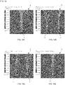
- Figs. 13 to 15 illustrate simulation results of distribution of flow speed vectors of the water W in the tank 1, concentration distribution of air bubbles, and horizontal flow speed of the water W for the reference example and the examples of the present invention.
- a test was performed for the air diffuser 4 (refer to Fig. 10 ) according to the second example of the present invention in addition to the air diffuser 4 according to the reference example (refer to Fig. 6 ) and the air diffuser 4 according to the first example (refer to Fig. 3 ).
- This air diffuser 5 includes a central body having a cylindrical shape and extending in the horizontal direction, and an air diffusion body having a film shape and provided to cover the circumferential surface of the central body, and air diffusion holes are arranged to both side surfaces of the air diffusion body. Air is fed to the gap between the central body and the air diffusion body and discharged to the outside through the air diffusion holes of both side surfaces.
- the air diffuser 5 having a cylindrical shape and including the air diffusion body and the central body has a diameter of 66 mm in a state in which air sending is stopped, and an air diffusion region arranged at each side surface along the cylindrical surface of the central body has a width (dimension in the circumferential direction) of 60 mm (120 mm in total).
- the inner wall of the tank 1 had a width of 1.4 m and a depth of 1.4 m, and the water depth was 1.4 m as well.
- Each air diffuser in the longitudinal direction had a dimension (corresponding to the length L in Fig. 3 ) of 1.2 m and was disposed at the height of 0.1 m from the bottom surface of the tank 1 with its longitudinal direction aligned with the depth direction.
- the number of installed air diffusers was one in the reference example and the other reference example and two in the first and second examples. In other words, the total area of air diffusion regions per bottom area of the tank 1 was set to be same in each reference example and each example.
- the air-sending volume was 40 Nm 3 /(m 2 ⁇ hr).
- Fig. 13 is a diagram illustrating, in a simplified manner, the simulation result of distribution of flow speed vectors of the water W in the tank 1 in which the air diffusers 4 according to the reference example and the examples are installed.
- the ascending speed of the water W above each air diffuser 4 is slower in the examples illustrated in Fig. 13B and Fig. 13C than in the reference example illustrated in Fig. 13A . It is thought that this reflects the magnitude of the ascending speed of air bubbles as described above.
- Fig. 13D illustrates flow speed vectors of the water W when the air diffuser 5 according to the other reference example is actuated.
- the width (dimension in the circumferential direction) of each region (corresponding to the air diffusion region R in the examples and the reference example) disposed on both side surfaces and including air diffusion holes is equal to that of the air diffusers 4 according to the first and second examples described above and smaller than that of the reference example, but the flow speed vectors of the water W upward from the air diffuser 5 are extremely large and are much larger than in a case of the reference example illustrated in Fig. 13A .
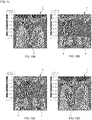
- Fig. 14 illustrates the concentration distribution of air bubbles in the tank 1.
- the concentration of air bubbles immediately near the air diffuser 4 is extremely high, and a region in which the concentration of air bubbles is relatively high is widely distributed up to near the water surface.
- distribution of the region in which the concentration of air bubbles is high is narrower than that in the reference example illustrated in Fig. 14A .
- the region in which the concentration of air bubbles is high extends long upward from the right and left side surfaces of the main body, and it is thought that air bubbles are likely to coalesce in the region.
- Fig. 15 illustrates distribution of the flow speed of the water W in the horizontal direction in the tank 1.
- a region in which the flow speed in the horizontal direction is fast spreads about a position immediately near the air diffuser 4, which is thought to cause narrowing of the width of the distribution range of air bubbles as illustrated in Fig. 12 or Fig. 14A
- the region in which the flow speed in the horizontal direction is fast is narrower than in the reference example illustrated in Fig. 15A
- the region in which the flow speed in the horizontal direction is fast is larger than in the reference example illustrated in Fig. 15A .
- the width D of the air diffusion region R in each air diffuser 4 is preferably set to be equal to or larger than 10 mm and smaller than 120 mm, more preferably set to be equal to or larger than 30 mm and equal to or smaller than 90 mm. It is thought that the above-described effects are basically more effective as the width D is narrower, but the frame 4d holding the air diffusion body 4c needs to have a certain width for structural reasons.
- each air diffuser 4 when the width D of the air diffusion region R in each air diffuser 4 is excessively narrow to have the area of the air diffusion region R necessary as the entire tank 1, the area of the frame 4d is larger than the air diffusion region R, and as a result, the bottom part of the tank 1 is mostly covered by the air diffuser 4 when the area of the air diffusion region R is globally ensured.
- Increase of the area of each air diffuser 4 causes increase of manufacturing cost, and furthermore, when the ratio of the installation area of the air diffuser 4 relative to the bottom area of the tank 1 is too high, motion of the water W in the tank 1 is encumbered, and such a failure that a necessary material such as oxygen does not reach the bottom part potentially occurs.
- the width D of the air diffusion region R in each air diffuser 4 is equal to or larger than 10 mm or 30 mm as described above.
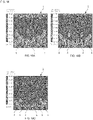
- Figs. 16 to 18 each illustrate a simulation result of the relation between the width D of the air diffusion region R and the corresponding one of the distribution of flow speed vectors of the water W in the tank 1, the concentration distribution of air bubbles, and the horizontal flow speed of the water W, the simulation result being obtained by additionally changing the width of the air diffusion region and the number of disposed air diffusers.
- Figs. A illustrates a case (corresponding to the above-described reference example) in which air diffusers 4 with the width D of the air diffusion region R set to be 120 mm are installed
- Figs. B illustrates a case in which air diffusers 4 with the width D set to be 90 mm are installed
- FIG. C illustrates a case (corresponding to the above-described first example) in which air diffusers 4 with the width D is set to be 60 mm are installed.
- the number of air diffusers 4 installed in the tank 1 is three in Figs. A, four in Figs. B, and six in Figs. C to set the equal total area of air diffusion regions per bottom area of the tank 1.
- Fig. 17 illustrates the concentration distribution of air bubbles in the tank 1: the concentration of air bubbles immediately near each air diffuser 4 is extremely high in Fig. 17A ; and distribution of the region in which the concentration of air bubbles is high is narrower in Fig. 17B and Fig. 17C than in the reference example illustrated in Fig. 17A .
- Fig. 17 illustrates the concentration distribution of air bubbles in the tank 1: the concentration of air bubbles immediately near each air diffuser 4 is extremely high in Fig. 17A ; and distribution of the region in which the concentration of air bubbles is high is narrower in Fig. 17B and Fig. 17C than in the reference example
- FIG. 18 illustrates distribution of the flow speed of the water W in the horizontal direction in the tank 1: the region in which the flow speed in the horizontal direction is fast largely spreads about each air diffuser 4 in Fig. 18A but is narrow in Fig. 18B and Fig. 18C .
- the width D of the air diffusion region R is set to be smaller than 120 mm, it is possible to decrease the ascending speed of air bubbles and the flow speed of the water W in the tank 1, narrow the region in which the concentration of air bubbles is high, and increase the distribution range of air bubbles, thereby reducing the air bubble diameter and improving the efficiency of oxygen solubility.
- the air diffuser 4 includes: the bottom panel 4b provided in the horizontal direction in the tank 1 in which the water W is filled; the air diffusion body 4c installed to cover the bottom panel 4b from above; and the air diffusion holes 4e arranged to penetrate through the air diffusion body 4c, the gas (air) A fed to the gap between the bottom panel 4b and the air diffusion body 4c is discharged into the water W through the air diffusion holes 4e, and the air diffusion region R where the air diffusion holes 4e are arranged in the air diffusion body 4c has a width D equal to or larger than 10 mm and smaller than 120 mm.
- the air diffusion holes 4e may be arranged in the entire range of the air diffusion body 4c in the width direction.
- the air diffusion holes 4e may be arranged in a partial region of the air diffusion body 4c in the width direction.
- the air diffuser of the present invention is not limited to the above-described examples but may be modified in various manners without departing from the scope of the present invention.
Landscapes
- Chemical & Material Sciences (AREA)
- Life Sciences & Earth Sciences (AREA)
- Chemical Kinetics & Catalysis (AREA)
- Biodiversity & Conservation Biology (AREA)
- Microbiology (AREA)
- Hydrology & Water Resources (AREA)
- Engineering & Computer Science (AREA)
- Environmental & Geological Engineering (AREA)
- Water Supply & Treatment (AREA)
- Organic Chemistry (AREA)
- Aeration Devices For Treatment Of Activated Polluted Sludge (AREA)
Applications Claiming Priority (2)
| Application Number | Priority Date | Filing Date | Title |
|---|---|---|---|
| JP2019174346A JP7769464B2 (ja) | 2019-09-25 | 2019-09-25 | 散気装置 |
| PCT/JP2020/036138 WO2021060417A1 (ja) | 2019-09-25 | 2020-09-24 | 散気装置 |
Publications (2)
| Publication Number | Publication Date |
|---|---|
| EP4035765A1 true EP4035765A1 (de) | 2022-08-03 |
| EP4035765A4 EP4035765A4 (de) | 2023-10-18 |
Family
ID=75156278
Family Applications (1)
| Application Number | Title | Priority Date | Filing Date |
|---|---|---|---|
| EP20869566.8A Pending EP4035765A4 (de) | 2019-09-25 | 2020-09-24 | Luftdiffusor |
Country Status (7)
| Country | Link |
|---|---|
| US (2) | US20220347636A1 (de) |
| EP (1) | EP4035765A4 (de) |
| JP (1) | JP7769464B2 (de) |
| KR (1) | KR102601504B1 (de) |
| CN (1) | CN114466826A (de) |
| AU (1) | AU2020353550B9 (de) |
| WO (1) | WO2021060417A1 (de) |
Families Citing this family (1)
| Publication number | Priority date | Publication date | Assignee | Title |
|---|---|---|---|---|
| WO2025069563A1 (ja) * | 2023-09-29 | 2025-04-03 | 株式会社村田製作所 | 気泡形成装置及び気泡形成方法 |
Family Cites Families (24)
| Publication number | Priority date | Publication date | Assignee | Title |
|---|---|---|---|---|
| US2978234A (en) * | 1951-01-16 | 1961-04-04 | Fmc Corp | Diffuser tube |
| DE3474949D1 (en) * | 1984-08-16 | 1988-12-08 | Rudolf Messner | Fine-bubble diffuser for aeration of water |
| DE9006868U1 (de) * | 1990-06-19 | 1990-10-04 | Venator Inc., Victor, Id. | Vorrichtung zum Belüften von Wasser |
| US5133862A (en) * | 1991-01-31 | 1992-07-28 | Fmc Corporation | Flexible membrane diffuser |
| CH685627A5 (de) * | 1992-08-31 | 1995-08-31 | Bontec Ag | Gasverteiler zum feinblasigen Belüften von Wasser. |
| US5858283A (en) * | 1996-11-18 | 1999-01-12 | Burris; William Alan | Sparger |
| EP0947471A1 (de) * | 1998-03-03 | 1999-10-06 | Huber + Suhner AG Kabel-, Kautschuk-, Kunststoffwerke | Belüftungsvorrichtung für Wasser und Verfahren zur Herstellung einer Belüftungsvorrichtung |
| AT409623B (de) * | 1999-04-28 | 2002-09-25 | Aquaconsult Anlagenbau Gmbh | Flotationsanlage |
| JP2003024974A (ja) * | 2001-07-13 | 2003-01-28 | Ngk Insulators Ltd | 散気装置及びこれを用いた曝気槽 |
| US6841083B2 (en) * | 2002-06-27 | 2005-01-11 | Ethicon, Inc. | Device and process for improved scouring efficiency |
| AU2003256405A1 (en) * | 2002-08-13 | 2004-02-25 | Itt Manufacturing Enterprises, Inc. | Strip diffuser pct i |
| US8002249B2 (en) | 2002-08-13 | 2011-08-23 | Itt Manufacturing Enterprises, Inc. | Strip diffuser |
| KR200321616Y1 (ko) * | 2003-04-16 | 2003-07-31 | 주식회사 신일 | 초 미세기포 발생용 산기장치 |
| US7806389B2 (en) * | 2005-10-26 | 2010-10-05 | Parkson Corporation | Flexible aeration panel and methods of use |
| US8002248B2 (en) * | 2008-06-19 | 2011-08-23 | Kang Na Hsiung Enterprise Co., Ltd. | Diffuser for an aeration system |
| JP2011230068A (ja) | 2010-04-28 | 2011-11-17 | Ael:Kk | 散気体 |
| US20130154132A1 (en) * | 2011-12-05 | 2013-06-20 | Parkson Corporation | Liftable aeration assembly and methods of placing an aeration assembly into a receptacle |
| KR101266507B1 (ko) * | 2012-11-19 | 2013-05-27 | (주)에이엔티이십일 | 산기장치 |
| DE102013106845B4 (de) | 2013-07-01 | 2017-06-14 | NORRES Beteiligungs-GmbH | Vorrichtung zur Verteilung von Gasen in Flüssigkeiten |
| US9862628B2 (en) * | 2013-10-04 | 2018-01-09 | Ovivo Inc. | Adjustable variable bubble size aeration for submerged membrane air scour |
| JP6246610B2 (ja) | 2014-02-12 | 2017-12-13 | 三機工業株式会社 | 散気装置 |
| JP6196941B2 (ja) * | 2014-06-13 | 2017-09-13 | 住友重機械エンバイロメント株式会社 | 散気板、散気装置及び散気板の取付方法 |
| JP2016198700A (ja) | 2015-04-08 | 2016-12-01 | 日東電工株式会社 | 散気部材、散気板及び散気装置 |
| AU2018340870B2 (en) | 2017-09-29 | 2024-06-20 | Aquatec Maxcon Pty Ltd | Diffuser for aeration of a fluid |
-
2019
- 2019-09-25 JP JP2019174346A patent/JP7769464B2/ja active Active
-
2020
- 2020-09-24 KR KR1020227008003A patent/KR102601504B1/ko active Active
- 2020-09-24 WO PCT/JP2020/036138 patent/WO2021060417A1/ja not_active Ceased
- 2020-09-24 US US17/763,008 patent/US20220347636A1/en not_active Abandoned
- 2020-09-24 AU AU2020353550A patent/AU2020353550B9/en active Active
- 2020-09-24 CN CN202080065540.1A patent/CN114466826A/zh active Pending
- 2020-09-24 EP EP20869566.8A patent/EP4035765A4/de active Pending
-
2024
- 2024-10-29 US US18/930,346 patent/US20250050286A1/en active Pending
Also Published As
| Publication number | Publication date |
|---|---|
| KR20220075311A (ko) | 2022-06-08 |
| US20250050286A1 (en) | 2025-02-13 |
| JP2021049499A (ja) | 2021-04-01 |
| AU2020353550A1 (en) | 2022-04-07 |
| KR102601504B1 (ko) | 2023-11-14 |
| CN114466826A (zh) | 2022-05-10 |
| EP4035765A4 (de) | 2023-10-18 |
| AU2020353550B2 (en) | 2023-07-27 |
| WO2021060417A1 (ja) | 2021-04-01 |
| US20220347636A1 (en) | 2022-11-03 |
| JP7769464B2 (ja) | 2025-11-13 |
| AU2020353550B9 (en) | 2023-11-23 |
Similar Documents
| Publication | Publication Date | Title |
|---|---|---|
| US20250050286A1 (en) | Air diffuser | |
| US7264231B2 (en) | Diffused gas aeration apparatus | |
| US20100300965A1 (en) | Diffuser apparatus, and diffuser apparatus running method | |
| KR101424949B1 (ko) | 액막 산기장치 | |
| US4879046A (en) | Local water cleaning method for use in consecutive water areas | |
| JP2008132464A (ja) | 曝気装置 | |
| JP5003999B2 (ja) | 廃水処理方法及び装置 | |
| WO2013175994A1 (ja) | 散気装置 | |
| JP2005103387A (ja) | 散気システム及び散気ユニット | |
| JP6196941B2 (ja) | 散気板、散気装置及び散気板の取付方法 | |
| JP2007014842A (ja) | 散気ユニット、散気装置及び曝気設備 | |
| US10766001B2 (en) | Aerator apparatus and air diffusion apparatus comprising same | |
| KR102388646B1 (ko) | 기판 처리 장치 | |
| JP7573502B2 (ja) | 複層型処理槽 | |
| JP2007296470A (ja) | 水中曝気装置 | |
| KR102146876B1 (ko) | 유체의 난류, 분사, 및 확산 반응의 일체형 고효율 미생물 반응기 | |
| US5211508A (en) | Total water circulation system for shallow water areas | |
| KR101971427B1 (ko) | 미세기포 발생용 산기장치 시스템 | |
| US11254595B2 (en) | Microbubble aerator | |
| KR102956415B1 (ko) | 플라즈마 모듈을 이용한 폐회로 타입 수처리 시스템 | |
| JP4778260B2 (ja) | 炭酸泉の製造装置 | |
| US10857506B2 (en) | Gas dissolution accelerating device | |
| KR20260019715A (ko) | 산소 용해 장치 및 이를 이용한 산소 용해 방법 | |
| JPS6153119B2 (de) | ||
| JPH078079Y2 (ja) | 汚水浄化装置 |
Legal Events
| Date | Code | Title | Description |
|---|---|---|---|
| STAA | Information on the status of an ep patent application or granted ep patent |
Free format text: STATUS: THE INTERNATIONAL PUBLICATION HAS BEEN MADE |
|
| PUAI | Public reference made under article 153(3) epc to a published international application that has entered the european phase |
Free format text: ORIGINAL CODE: 0009012 |
|
| STAA | Information on the status of an ep patent application or granted ep patent |
Free format text: STATUS: REQUEST FOR EXAMINATION WAS MADE |
|
| 17P | Request for examination filed |
Effective date: 20220407 |
|
| AK | Designated contracting states |
Kind code of ref document: A1 Designated state(s): AL AT BE BG CH CY CZ DE DK EE ES FI FR GB GR HR HU IE IS IT LI LT LU LV MC MK MT NL NO PL PT RO RS SE SI SK SM TR |
|
| DAV | Request for validation of the european patent (deleted) | ||
| DAX | Request for extension of the european patent (deleted) | ||
| REG | Reference to a national code |
Ref country code: DE Ref legal event code: R079 Free format text: PREVIOUS MAIN CLASS: B01F0003040000 Ipc: C02F0003200000 |
|
| A4 | Supplementary search report drawn up and despatched |
Effective date: 20230920 |
|
| RIC1 | Information provided on ipc code assigned before grant |
Ipc: B01F 23/231 20220101ALI20230914BHEP Ipc: C02F 3/20 20060101AFI20230914BHEP |