EP4035954B1 - Dispositif coussin gonflable et siège de véhicule - Google Patents
Dispositif coussin gonflable et siège de véhicule Download PDFInfo
- Publication number
- EP4035954B1 EP4035954B1 EP20869533.8A EP20869533A EP4035954B1 EP 4035954 B1 EP4035954 B1 EP 4035954B1 EP 20869533 A EP20869533 A EP 20869533A EP 4035954 B1 EP4035954 B1 EP 4035954B1
- Authority
- EP
- European Patent Office
- Prior art keywords
- airbag
- seatback
- occupant
- vehicle seat
- connecting members
- Prior art date
- Legal status (The legal status is an assumption and is not a legal conclusion. Google has not performed a legal analysis and makes no representation as to the accuracy of the status listed.)
- Active
Links
Images




Classifications
-
- B—PERFORMING OPERATIONS; TRANSPORTING
- B60—VEHICLES IN GENERAL
- B60R—VEHICLES, VEHICLE FITTINGS, OR VEHICLE PARTS, NOT OTHERWISE PROVIDED FOR
- B60R21/00—Arrangements or fittings on vehicles for protecting or preventing injuries to occupants or pedestrians in case of accidents or other traffic risks
- B60R21/02—Occupant safety arrangements or fittings, e.g. crash pads
- B60R21/16—Inflatable occupant restraints or confinements designed to inflate upon impact or impending impact, e.g. air bags
- B60R21/20—Arrangements for storing inflatable members in their non-use or deflated condition; Arrangement or mounting of air bag modules or components
- B60R21/207—Arrangements for storing inflatable members in their non-use or deflated condition; Arrangement or mounting of air bag modules or components in vehicle seats
-
- B—PERFORMING OPERATIONS; TRANSPORTING
- B60—VEHICLES IN GENERAL
- B60N—SEATS SPECIALLY ADAPTED FOR VEHICLES; VEHICLE PASSENGER ACCOMMODATION NOT OTHERWISE PROVIDED FOR
- B60N2/00—Seats specially adapted for vehicles; Arrangement or mounting of seats in vehicles
- B60N2/24—Seats specially adapted for vehicles; Arrangement or mounting of seats in vehicles for particular purposes or particular vehicles
- B60N2/42—Seats specially adapted for vehicles; Arrangement or mounting of seats in vehicles for particular purposes or particular vehicles the seat constructed to protect the occupant from the effect of abnormal g-forces, e.g. crash or safety seats
-
- B—PERFORMING OPERATIONS; TRANSPORTING
- B60—VEHICLES IN GENERAL
- B60N—SEATS SPECIALLY ADAPTED FOR VEHICLES; VEHICLE PASSENGER ACCOMMODATION NOT OTHERWISE PROVIDED FOR
- B60N2/00—Seats specially adapted for vehicles; Arrangement or mounting of seats in vehicles
- B60N2/24—Seats specially adapted for vehicles; Arrangement or mounting of seats in vehicles for particular purposes or particular vehicles
- B60N2/42—Seats specially adapted for vehicles; Arrangement or mounting of seats in vehicles for particular purposes or particular vehicles the seat constructed to protect the occupant from the effect of abnormal g-forces, e.g. crash or safety seats
- B60N2/427—Seats or parts thereof displaced during a crash
- B60N2/42709—Seats or parts thereof displaced during a crash involving residual deformation or fracture of the structure
- B60N2/42718—Seats or parts thereof displaced during a crash involving residual deformation or fracture of the structure with anti-submarining systems
-
- B—PERFORMING OPERATIONS; TRANSPORTING
- B60—VEHICLES IN GENERAL
- B60N—SEATS SPECIALLY ADAPTED FOR VEHICLES; VEHICLE PASSENGER ACCOMMODATION NOT OTHERWISE PROVIDED FOR
- B60N2/00—Seats specially adapted for vehicles; Arrangement or mounting of seats in vehicles
- B60N2/24—Seats specially adapted for vehicles; Arrangement or mounting of seats in vehicles for particular purposes or particular vehicles
- B60N2/42—Seats specially adapted for vehicles; Arrangement or mounting of seats in vehicles for particular purposes or particular vehicles the seat constructed to protect the occupant from the effect of abnormal g-forces, e.g. crash or safety seats
- B60N2/427—Seats or parts thereof displaced during a crash
- B60N2/42727—Seats or parts thereof displaced during a crash involving substantially rigid displacement
- B60N2/42754—Seats or parts thereof displaced during a crash involving substantially rigid displacement of the cushion
- B60N2/42763—Seats or parts thereof displaced during a crash involving substantially rigid displacement of the cushion with anti-submarining systems
-
- B—PERFORMING OPERATIONS; TRANSPORTING
- B60—VEHICLES IN GENERAL
- B60R—VEHICLES, VEHICLE FITTINGS, OR VEHICLE PARTS, NOT OTHERWISE PROVIDED FOR
- B60R21/00—Arrangements or fittings on vehicles for protecting or preventing injuries to occupants or pedestrians in case of accidents or other traffic risks
- B60R21/02—Occupant safety arrangements or fittings, e.g. crash pads
- B60R21/16—Inflatable occupant restraints or confinements designed to inflate upon impact or impending impact, e.g. air bags
- B60R21/23—Inflatable members
- B60R21/231—Inflatable members characterised by their shape, construction or spatial configuration
- B60R21/23138—Inflatable members characterised by their shape, construction or spatial configuration specially adapted for side protection
-
- B—PERFORMING OPERATIONS; TRANSPORTING
- B60—VEHICLES IN GENERAL
- B60R—VEHICLES, VEHICLE FITTINGS, OR VEHICLE PARTS, NOT OTHERWISE PROVIDED FOR
- B60R21/00—Arrangements or fittings on vehicles for protecting or preventing injuries to occupants or pedestrians in case of accidents or other traffic risks
- B60R21/02—Occupant safety arrangements or fittings, e.g. crash pads
- B60R21/16—Inflatable occupant restraints or confinements designed to inflate upon impact or impending impact, e.g. air bags
- B60R21/23—Inflatable members
- B60R21/231—Inflatable members characterised by their shape, construction or spatial configuration
- B60R21/233—Inflatable members characterised by their shape, construction or spatial configuration comprising a plurality of individual compartments; comprising two or more bag-like members, one within the other
-
- B—PERFORMING OPERATIONS; TRANSPORTING
- B60—VEHICLES IN GENERAL
- B60R—VEHICLES, VEHICLE FITTINGS, OR VEHICLE PARTS, NOT OTHERWISE PROVIDED FOR
- B60R21/00—Arrangements or fittings on vehicles for protecting or preventing injuries to occupants or pedestrians in case of accidents or other traffic risks
- B60R21/02—Occupant safety arrangements or fittings, e.g. crash pads
- B60R21/16—Inflatable occupant restraints or confinements designed to inflate upon impact or impending impact, e.g. air bags
- B60R21/23—Inflatable members
- B60R21/231—Inflatable members characterised by their shape, construction or spatial configuration
- B60R21/2334—Expansion control features
- B60R21/2338—Tethers
-
- B—PERFORMING OPERATIONS; TRANSPORTING
- B60—VEHICLES IN GENERAL
- B60R—VEHICLES, VEHICLE FITTINGS, OR VEHICLE PARTS, NOT OTHERWISE PROVIDED FOR
- B60R21/00—Arrangements or fittings on vehicles for protecting or preventing injuries to occupants or pedestrians in case of accidents or other traffic risks
- B60R2021/003—Arrangements or fittings on vehicles for protecting or preventing injuries to occupants or pedestrians in case of accidents or other traffic risks characterised by occupant or pedestian
- B60R2021/0032—Position of passenger
- B60R2021/0034—Position of passenger lying down
-
- B—PERFORMING OPERATIONS; TRANSPORTING
- B60—VEHICLES IN GENERAL
- B60R—VEHICLES, VEHICLE FITTINGS, OR VEHICLE PARTS, NOT OTHERWISE PROVIDED FOR
- B60R21/00—Arrangements or fittings on vehicles for protecting or preventing injuries to occupants or pedestrians in case of accidents or other traffic risks
- B60R2021/003—Arrangements or fittings on vehicles for protecting or preventing injuries to occupants or pedestrians in case of accidents or other traffic risks characterised by occupant or pedestian
- B60R2021/0039—Body parts of the occupant or pedestrian affected by the accident
- B60R2021/0048—Head
-
- B—PERFORMING OPERATIONS; TRANSPORTING
- B60—VEHICLES IN GENERAL
- B60R—VEHICLES, VEHICLE FITTINGS, OR VEHICLE PARTS, NOT OTHERWISE PROVIDED FOR
- B60R21/00—Arrangements or fittings on vehicles for protecting or preventing injuries to occupants or pedestrians in case of accidents or other traffic risks
- B60R21/02—Occupant safety arrangements or fittings, e.g. crash pads
- B60R21/16—Inflatable occupant restraints or confinements designed to inflate upon impact or impending impact, e.g. air bags
- B60R21/23—Inflatable members
- B60R21/231—Inflatable members characterised by their shape, construction or spatial configuration
- B60R21/23138—Inflatable members characterised by their shape, construction or spatial configuration specially adapted for side protection
- B60R2021/23146—Inflatable members characterised by their shape, construction or spatial configuration specially adapted for side protection seat mounted
-
- B—PERFORMING OPERATIONS; TRANSPORTING
- B60—VEHICLES IN GENERAL
- B60R—VEHICLES, VEHICLE FITTINGS, OR VEHICLE PARTS, NOT OTHERWISE PROVIDED FOR
- B60R21/00—Arrangements or fittings on vehicles for protecting or preventing injuries to occupants or pedestrians in case of accidents or other traffic risks
- B60R21/02—Occupant safety arrangements or fittings, e.g. crash pads
- B60R21/16—Inflatable occupant restraints or confinements designed to inflate upon impact or impending impact, e.g. air bags
- B60R21/23—Inflatable members
- B60R21/231—Inflatable members characterised by their shape, construction or spatial configuration
- B60R21/2334—Expansion control features
- B60R21/2338—Tethers
- B60R2021/23386—External tether means
-
- B—PERFORMING OPERATIONS; TRANSPORTING
- B60—VEHICLES IN GENERAL
- B60R—VEHICLES, VEHICLE FITTINGS, OR VEHICLE PARTS, NOT OTHERWISE PROVIDED FOR
- B60R21/00—Arrangements or fittings on vehicles for protecting or preventing injuries to occupants or pedestrians in case of accidents or other traffic risks
- B60R21/02—Occupant safety arrangements or fittings, e.g. crash pads
- B60R21/16—Inflatable occupant restraints or confinements designed to inflate upon impact or impending impact, e.g. air bags
- B60R21/26—Inflatable occupant restraints or confinements designed to inflate upon impact or impending impact, e.g. air bags characterised by the inflation fluid source or means to control inflation fluid flow
- B60R2021/26058—Inflatable occupant restraints or confinements designed to inflate upon impact or impending impact, e.g. air bags characterised by the inflation fluid source or means to control inflation fluid flow using a combination of inflators
Definitions
- the present invention relates to a vehicle seat with an airbag device installed in said seat.
- the present invention relates to a vehicle seat with an airbag device that can reliably restrain the occupant in question regardless of the posture of the occupant seated in the seat.
- airbags include, for example, various forms such as: a so-called driver airbag which is deployed from near the center of the steering wheel so as to protect the driver; a curtain airbag which is deployed downward on the inner side of the window of an automobile so as to protect occupants during collisions in the transverse direction of a vehicle, as well as when overturning and during rollover accidents; and a side airbag which is deployed between the occupant and the side panel so as to protect the occupant upon impact in the transverse direction of a vehicle.
- driver airbag which is deployed from near the center of the steering wheel so as to protect the driver
- curtain airbag which is deployed downward on the inner side of the window of an automobile so as to protect occupants during collisions in the transverse direction of a vehicle, as well as when overturning and during rollover accidents
- side airbag which is deployed between the occupant and the side panel so as to protect the occupant upon impact in the transverse direction of a vehicle.
- the present invention has been created in view of the abovementioned problems; an object thereof is to provide a vehicle seat with an airbag device that may reliably restrain the occupant regardless of the posture of the occupant seated in the seat.
- the direction the occupant faces is referred to as the "front,” the opposite direction is referred to as the "rear,” and the direction indicating the coordinate axis is referred to as the "front-to-back direction.”
- the right of the occupant is referred to as "right direction”
- the left of the occupant is referred to as "left direction”
- the direction indicating the coordinate axis is referred to as the "left-right direction.”
- the head direction of the passenger is referred to as "up”
- the waist direction of the passenger is referred to as "down”
- the direction indicating the coordinate axis is referred to as the "vertical direction.”
- the present invention is a vehicle seat with an airbag device installed in the vehicle seat having a seat cushion forming the seat surface and a seatback forming the backrest, a pair of inflators stowed in the left and right side portions of the seatback that generate expansion gas, and an airbag stowed in the seatback in a rolled or folded state and deployed by the expansion gas released from said inflators.
- the airbag is configured to include a pair of left and right side chambers that deploy from the side of the seatback toward the front and restrain movement of at least the waist to the shoulders of an occupant, and a connection part that connects the pair of side chambers and is positioned above the head of the occupant when the airbag is deployed wherein a second connecting member in the shape of a strip with a first end portion connected near the lower end area of the airbag in the stowed state and a second end portion connected to the side part of the seat cushion can be further provided on both the left and right sides of the sea.
- the airbag By configuring the airbag to include a pair of left and right side chambers that restrain movement of the occupant from the waist to the shoulders, and a connection part that connects the pair of side chambers positioned above the occupant's head, the airbag deploys in a dome shape to cover the occupant seated in the seat. As a result, the airbag can reliably restrain movement of the occupant at least in the left-right direction, upward, and diagonally upward, and provide suitable protection from the head to the waist of the occupant.
- the restraint performance near the waist area of the occupant seated in the seat can be improved.
- the waist which is close to the occupant center of gravity, moves in a direction that pushes the airbag outward
- the second connecting members can securely retain the airbag and avoid a situation where the occupant is flung out laterally.
- the airbag connection part can comprise an expandable upper chamber that connects to the side chambers, and the upper chamber can be configured to deploy from near the upper edge of the seatback and deploy so as to encompass the occupant's head.
- the expandable upper chamber deploys so as to encompass the occupant's head, thereby mitigating impact to the head.
- the upper chamber can be configured to deploy from near the rear edge of the top of the seatback.
- the upper chamber deploys from near the rear edge of the upper edge of the seatback, so that the upper chamber covers the back of the occupant's head from behind to in front of the occupant's head, thus avoiding direct impact on the occupant's head when the airbag deploys and creating a broad area of protection around the occupant's head.
- the expansion gas released from the inflator can be configured to flow from the side chambers to the upper chamber.
- the side chambers By configuring the expansion gas to flow from the side chambers to the upper chamber, the side chambers can be deployed first to quickly restrain the lateral movement of the occupant, and then the upper chamber can be deployed to softly protect the head of the occupant. In other words, the head and neck of the occupant, which are vulnerable to impacts, will not be subjected to a large impact from the initial stage of airbag deployment.
- the airbag can be equipped with a plurality of first connecting members for securing said airbag to the seatback when stowed.
- the possibility of a gap between the seatback and the airbag during deployment of the airbag can be reduced.
- the occupant will not protrude through the gap between the airbag and the seatback, and the occupant can be securely restrained.
- the first connecting members can be provided with at least one each above and below the inflator on the left and right side portions of the seatback.
- Installing first connecting members at least one each, above and below the inflator enables securing the area around the inflator where the greatest pressure is generated in the initial stage of airbag deployment, thereby stabilizing the deployment behavior of the airbag.
- the first connecting members can be installed in the head region, chest to abdomen region, and waist region of the occupant on the left and right side portions of the seatback.
- the entire range from the waist up of the occupant seated in the seat can be restrained and protected.
- the first end portion of the second connecting members can be connected near the front end portion of the side chamber in the deployed state.
- the deployment posture of the side chamber can be maintained in an appropriate state. If the second connecting members are connected near the rear end portion of the side chamber, it is assumed that the forward portion of the side chamber will be out of control when the airbag deploys, and the behavior will not be stable. In this regard, if the second connecting members are connected near the front end portion of the side chamber, the posture of the forward portion of the deployed side chamber can be reliably maintained, and the occupant restraint performance can be improved.
- the seat cushion can be further provided with a lower connection part that extends generally along the vehicle width direction in the interior or bottom of the seat cushion and connects the second end portions of the left and right pairs of second connecting members.
- a lower connection part extending in the vehicle width direction under the seat cushion, the second end portions of the second connecting members can be secured more reliably.
- the pair of second connecting members and the lower connection part can be formed as a single tether.
- the second connecting members and the lower connection part is made into a single tether, in addition to simplifying the structure (reducing the number of parts), the overall strength can be increased by omitting the connection part.
- the lower connection part can be configured to extend in the vehicle width direction forward of the center of the seat cushion in the front-to-back direction.
- the second end portions of the second connecting members are placed in a position more forward than the first end portions thereof, thereby imparting suitable tension to the second connecting members.
- the lower connection part is preferably configured to push the seat cushion upward based on tension generated in the second connecting members when the airbag is deployed.
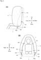
- FIG. 1 is a side view (A) and front view (B) illustrating an airbag device 1 according to embodiment 1 of the present invention mounted in a vehicle seat (2, 3), where the vehicle seat (2, 3) is illustrated as see-through.
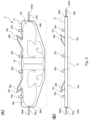
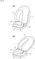
- FIG. 2 illustrates the structure of an airbag 14 used in the airbag device 1 according to embodiment 1.
- FIG. 2(A) is a plan view illustrating the state in which the airbag 14 is unfolded (state prior to being stowed).
- FIG. 2(B) is a front view illustrating the state in which the airbag is rolled (state when stowed).
- the airbag device 1 is equipped in a vehicle seat having a seat cushion 3 forming a seating surface and a seatback 2 forming a backrest.
- the airbag device 1 includes a pair of inflators 12a and 12b, which are stowed in the left and right side portions of the seatback 2 and generate expansion gas, and an airbag 14 stowed in the seatback 2 in a rolled or folded state that is deployed by the expansion gas discharged from the inflators 12a and 12b.
- the seatback 2 includes an integrated headrest, but this airbag device can also be applied to seats equipped with a headrest as a separate member.
- the airbag 14 is configured to include a pair of left and right side chambers 16a and 16b that deploy from the side of the seatback 2 toward the front and restrain movement of at least the waist to the shoulders of the occupant, and a connection part 18 that connects the pair of side chambers 16a and 16b and is positioned above the head of the occupant when the airbag 14 is deployed.
- the side chambers 16a and 16b can be symmetrical in shape.
- the connection part 18 is positioned in the longitudinal center of the airbag 14 when in an unfolded state before stowing ( FIG. 2 ) and is integrally formed using the same fabric as the side chambers 16a and 16b.
- the connection part 18 of the airbag 14 includes an expandable upper chamber that connects to the side chambers 16a and 16b, and the upper chamber is configured to expand from near the upper edge of the seatback 2 to encompass the head of the occupant ( FIG. 3 ).
- the expanded gas discharged from the inflators 12a and 12b flows from the side chambers 1 2a, 12b into the upper chamber (18).
- the connecting member 18 can also be configured as a non-expandable region. In this case, the thickness in the vertical direction becomes thinner.
- the airbag device 1 is provided with first connecting members (tabs) 22a, 22b, 22c, and 22d for securing the rolled and compressed airbag 14 to the seatback 2.
- the first connecting members 22a, 22b, 22c, 22d are arranged one above and one below the inflators 12a and 12b on the left and right side portions of the seatback 2.
- the inflators 12a and 12b are introduced through the inflator introduction portions 20a and 20b of the airbag 14.
- Installing the first connecting members 22a, 22b, 22c, 22d above and below the inflators 12a and 12b enables securing the area around the inflator where the greatest pressure is generated in the initial stage of deploying the airbag 14, thereby stabilizing the deployment behavior of the airbag 14.
- the first connecting members can be installed in the head region, chest to abdomen region, and waist region of the occupant in the left and right side portions of the seatback 2. In this case, it is possible to restrain and protect the entire range of occupants seated in the seat.
- the airbag device 1 is further provided with second connecting members 24a and 24b in the shape of a strip with first end portions (24a1, 24b1) connected to the lower end area of the airbag 14 and second end portions (24a2, 24b2) connected to the side part of the seat cushion 3, on both the left and right sides of the seat.
- the second connecting members 24a and 24b can be made of the same material (cloth) as the airbag 14.
- the first end portions (24a1, 24b1) of the second connecting members 24a and 24b are connected near the front end portion of the side chambers 16a and 16b in the deployed state thereof.
- FIG. 3 illustrates the activated state (airbag 14 deployed state) of the airbag device 1 according to embodiment 1.
- FIG. 3(A) illustrates a view of the side of the vehicle in the width direction
- FIG. 3(B) illustrates a view from the front.
- the inflators 12a and 12b release the expanding gas, causing the airbag 14 to expand and deploy.
- the airbag 14 begins to expand, the gas first flows into the side chambers 16a and 16b, and then into the upper chambers that make up the connection part 18. Then, the side chambers 16a and 16b expand from the side of the seatback 2 toward the front.
- the chamber of the connection part 18, is positioned above the head of the occupant, then expands forward.
- the airbag 14 By configuring the airbag 14 according to the present embodiment to include a pair of left and right side chambers 16a and 16b that restrain movement of the occupant from the waist to the shoulders, and a connection part 18 that connects the pair of side chambers 16a and 16b and is located above the head of the occupant, the airbag 14 deploys in a dome shape to cover the occupant seated in the seat 3. As a result, the airbag can reliably restrain movement of the occupant at least in the left-right direction, upward, and diagonally upward, and provide suitable protection from the head to the waist of the occupant.
- connection part 18 is formed as an expandable upper chamber, the connection part 18 expands to encompass the head of the occupant ( FIG. 3(B) ), which makes it possible to properly absorb impacts on the head.
- the side chambers 16a and 16b can be expanded first to quickly restrain the lateral movement of the occupant, and then the upper chamber 18 can be expanded to softly protect the head of the occupant. This means that the head and neck, which are vulnerable to impact, can be restrained (protected) relatively softly without applying a large impact in the initial stage of airbag 14 deployment.
- the upper chamber which constitutes the connection part 18, deploys from near the rear edge of the upper end of the seatback 2.
- the upper chamber 18 expands from near the rear edge of the upper end of the seatback 2, so that the upper chamber 18 covers the back of the head of the occupant from behind to in front. This avoids the upper chamber 18 directly impacting the head of the occupant when the airbag 14 deploys, and also makes it possible to create a wide area of protection around the head of the occupant.
- the connecting member 18 is designed to launch over the headrest from the top of the seatback and expand forward.
- the possibility of a gap between the seatback 2 and the airbag 14 during deployment of said airbag 14 can be reduced.
- the occupant will not protrude through the gap between the airbag 14 and the seatback 2, and the occupant can be securely restrained.
- second connecting members 24a and 24b in the shape of a strip that connects the lower end area of the airbag 14 to the side part of the seat cushion 3, the restraint performance near the waist area of the occupant seated in the seat (2, 3) can be improved.
- the waist which is close to the occupant center of gravity, moves in a direction that pushes the airbag 14 down outward, the second connecting members 24a and 24b can securely hold the airbag 14 and avoid a situation where the occupant is flung out laterally.
- the deployment posture of the side chambers 16a and 16b can be maintained in a suitable state. Assuming that the first end portions (24a1, 24b1) of the second connecting members 24a and 24b are connected near the rear end portion of the side chambers 16a and 16b, the forward portion of the side chambers 16a and 16b will be out of control when the airbag 14 deploys, and the behavior will not be stable.
- the deployment posture of the forward portion of the side chambers 16a and 16b can be suitably maintained (controlled), improving occupant restraining performance.
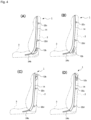
- FIG. 4 (A) to (D) are side views illustrating a modified example of the airbag device 1 according to embodiment 1, where the vehicle seat is illustrated as see-through.
- the inflators 12a, 12b are arranged on the lower end part of the seatback 2, and due to this, the first connecting members 22c and 22d (22a, 22b) are arranged near the head and waist of the occupant.
- the only difference between (A) and (B) is the direction in which the inflators 12a and 12b are inserted.
- inflators 12a and 12b are inserted from above, and in the example of the diagram (B), inflators 12a and 12b are inserted from below.
- the inflators 12a and 12b are arranged on the upper end part of the seatback 2, and due to this, the first connecting members 22c and 22d (22a, 22b) are arranged near the shoulder and waist of the occupant.
- the only difference between (A) and (B) is the direction in which the inflators 12a and 12b are inserted.
- inflators 12a and 12b are inserted from above, and in the example of the diagram (B), inflators 12a and 12b are inserted from below.
- a single inflator can be arranged at the back of the seatback 2 and configured to guide the expansion gas from there to both sides of the seatback 2.
- FIG. 5(A) is a plan view illustrating the structure of the airbag according to the modified example of embodiment 1, and FIG. 5(B) to (D) are plan views illustrating variations of the second connecting members.
- FIG. 5(A) is a drawing corresponding to FIG. 2(A) , and only the shape of the second connecting members (124a, 124b) are different, so only those parts will be described.
- the first end portions (124a1, 124b1) of the second connecting members (124a, 124b) are formed wider than the second end portions (124a2, 124b2) thereof.
- the second connecting members (124a, 124b) are generally formed in a trapezoidal shape, however, as illustrated in FIG. 5(B) to (D) , there are other variations such as a member 224 with the middle portion curved inward, a member 324 with a shape in which the width of the end portion is constant within a given range, and a member 424 which is formed in a triangular shape.
- the second connecting members (124a, 124b) of variations illustrated in FIG. 5 forming the first end portions 124a1 and 124b1 connected to the airbag wider than the second end portions 124a2 and 124b2 connected to the seat cushion stabilizes the deployment behavior at the lower end of the airbag.
- the second connecting members (124a, 124b) of the structure in FIG. 5 can also be applied to embodiment 2 described below.
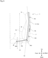
- FIG. 6 is a side view illustrating an airbag device 1 according to embodiment 2 of the present invention mounted in a vehicle seat (2, 3), where the vehicle seat (2, 3) is illustrated as see-through.
- FIG. 7 illustrates the non-activated state (stowed state) of the airbag device 1 according to embodiment 2.
- FIG. 7(A) illustrates a view from the front in the vehicle traveling direction
- FIG. 7(B) illustrates a view from the side in the vehicle width direction.
- FIG. 8 is a schematic perspective view illustrating the activated state (airbag deployed state) of the airbag device 1 according to embodiment 2.
- FIG. 8(A) illustrates a state in which the seatback 2 is not reclined or slightly reclined.
- FIG. 8(B) illustrates a state in which the seatback 2 is greatly reclined.
- FIG. 9 is a schematic view illustrating the activated state (airbag deployed state) of the airbag device 1 according to embodiment 2 as viewed from the side in the vehicle width direction.
- the airbag device 1 is further provided with a lower connection part 30 that extends generally along the vehicle width direction inside or at the bottom of the seat cushion 3 and connects the second end portions 24a2 and 24b2 of the pair of left and right second connecting members 24a and 24b.
- the pair of second connecting members 24a and 24b and the lower connection part 30 can be formed as a single tether.
- metal wires or other materials can be employed as the lower connection part 30.
- the lower connection part 30 can be placed inside the seat cushion 3 or through the space between the seat cushion 3 and the seat frame.
- the airbag 14 in a rolled and stowed state is positioned behind the longitudinal center line C2 of the seatback 2 and is secured along the center line C2.
- the code 2a indicates the side support and the code 2b indicates the receiving surface (the surface in contact with the back of the occupant).
- the center line C2 means a line that passes approximately through the middle of the receiving surface 2b and the back in the front-back direction of the seatback 2.
- the rolled airbag 14 can be placed above or in front of the center line C2 of the seatback 2.
- connection position of the second end portion 24b2 (24a2) of the second connecting member 24b (24a) and the lower connection part 30 is forward of the center line C3 in the front-to-back direction of the seat cushion 3.
- the lower connection part 30 is arranged to extend in the vehicle width direction in front of the center of the seat cushion 3 in the front-to-back direction (the waist center of the occupant).
- the length of the second connecting member 24b (24a) is preferably set as short as possible in a range that does not interfere with the reclining movement of the seatback 2 when the airbag device 1 is not activated.
- the inflators 12a and 12b discharge expansion gas to expand and deploy the airbag 14 ( FIG. 8 , FIG. 9 ).
- the airbag 14 begins to expand, the gas first flows into the side chambers 16a and 16b, and then into the upper chambers that make up the connection part 18. Then, the side chambers 16a and 16b expand from the side of the seatback 2 toward the front.
- the chamber of the connection part 18, is positioned above the head of the occupant, then expands forward. The operation up to this point is the same as in embodiment 1 described above.
- the lifting effect of the seat cushion 3 by the lower connection part 30 is more pronounced in a situation where the seat is greatly reclined (the seatback 2 is greatly tilted (see FIG. 8(B) ) than when the seat is not reclined (the seatback 2 is nearly vertical).
- the airbag 14 deploys while the seatback 2 is tilted backward, the lower end of the airbag 14 moves backward and at least the forward portion of the seat cushion 3 partially rises. This means that the lower end part of the airbag 14 will move away from the seat cushion 3. This will increase the tension applied to the second connecting members 24a and 24b and lower connection part 30 connected to the lower end part of the airbag 14, causing the seat cushion 3 to be lifted upward with a strong force.
- the seat cushion 3 may be deformed so that it is inclined backward as a whole.
- the second end portions (24a2, 24b2) of the second connecting members 24a and 24b can be secured more reliably.
- the lower connection part 30 can be composed of a flexible tether as described above, but instead of a tether, a plate made of rigid metal or resin can be employed. When the lower connection part 30 is composed of a rigid plate, the effect of lifting the thigh of the occupant is greater.
- connection part 30 when the second connecting members 24a and 24b and the lower connection part 30 is made into a single tether, in addition to simplifying the structure (reducing the number of parts), the overall strength can be increased by omitting the connection part.
- the second end portions (24a2, 24b2) of the second connecting members 24a and 24b are placed in a position more forward than the first end portions (24a1, 24b1) thereof when the airbag 14 deploys, thereby imparting suitable tension to the second connecting members 24a and 24b.
Landscapes
- Engineering & Computer Science (AREA)
- Mechanical Engineering (AREA)
- Aviation & Aerospace Engineering (AREA)
- Transportation (AREA)
- Air Bags (AREA)
- Seats For Vehicles (AREA)
Claims (12)
- Siège de véhicule comprenant un dispositif de coussin de sécurité gonflable (1) ayant un coussin de siège (3) formant la surface de siège et un dossier de siège (2) formant l'appui-dos, comprenant :une paire de gonfleurs (12a, 12b) rangés dans les côtés gauche et droit du dossier de siège (2) lesquels génèrent un gaz d'expansion ; etun coussin de sécurité gonflable (14) rangé dans le dossier de siège (2) dans un état enroulé ou plié déployé par le gaz d'expansion généré par les gonfleurs (12a, 12b), le coussin de sécurité gonflable (14) comportant :une paire de chambres latérales gauche et droite (16a, 16b) qui se déploient à partir de la partie latérale du dossier de siège (2) en direction de l'avant et limitent un mouvement d'au moins la taille jusqu'aux épaules de l'occupant ; etune partie de liaison (18) qui relie la paire de chambres latérales (16a, 16b) et est positionnée au-dessus de la tête de l'occupant lorsque le coussin de sécurité gonflable (14) est déployé caractérisé par un second élément de liaison (24a, 24b, 124a, 124b) sous la forme d'une bande avec une première portion d'extrémité (24a1, 24b1, 124a1, 124b1) reliée près de la zone d'extrémité inférieure du coussin de sécurité gonflable (14) dans l'état rangé et une seconde portion d'extrémité (24a2, 24b2, 124a2, 124b2) reliée à la partie latérale du coussin de siège (3) qui est fournie à la fois sur les côtés gauche et droit du siège.
- Siège de véhicule selon la revendication 1, dans lequella partie de liaison (18) du coussin de sécurité gonflable (14) comporte une chambre supérieure expansible reliée aux chambres latérales (16a, 16b), etla chambre supérieure est conçue de façon à se déployer à partir d'un point proche du bord supérieur du dossier de siège (2) pour englober la tête de l'occupant.
- Siège de véhicule selon la revendication 2, dans lequel la chambre supérieure est conçue de façon à se déployer à partir d'un point proche du bord arrière de l'extrémité supérieure du dossier de siège (2).
- Siège de véhicule selon la revendication 2 ou la revendication 3, dans lequel le gaz d'expansion libéré du gonfleur (12a, 12b) est conçu de façon à s'écouler des chambres latérales (16a, 16b) vers la chambre supérieure.
- Siège de véhicule selon l'une quelconque des revendications 1 à 4, dans lequel le coussin de sécurité gonflable (14) est pourvu d'une pluralité de premiers éléments de liaison (22a, 22b, 22c, 22d) permettant de fixer le coussin de sécurité gonflable (14) au dossier de siège (2) lorsqu'il est rangé.
- Siège de véhicule selon la revendication 5, dans lequel au moins l'un des premiers éléments de liaison (22a, 22b, 22c, 22d) est fourni au-dessus et en dessous du gonfleur (12a, 12b) sur les portions latérales gauche et droite du dossier de siège (2).
- Siège de véhicule selon la revendication 5, dans lequel les premiers éléments de liaison (22a, 22b, 22c, 22d) sont fournis dans les régions de la tête, du thorax à l'abdomen, et de la taille de l'occupant sur les portions latérales gauche et droite du dossier de siège (2).
- Siège de véhicule selon l'une quelconque des revendications 1 à 7, dans lequel la première portion d'extrémité (24a1, 24b1, 124a1, 124b1) du second élément de liaison (24a, 24b, 124a, 124b) est reliée près de la portion d'extrémité avant des chambres latérales (16a, 16b) dans l'état déployé.
- Siège de véhicule selon l'une quelconque des revendications 1 à 8, comprenant en outre une partie de liaison inférieure (30) s'étendant le long de la direction de largeur de véhicule à l'intérieur ou au fond du coussin de siège (3) et reliant les secondes portions d'extrémité (24a2, 24b2, 124a2, 124b2) de la paire gauche et droite des seconds éléments de liaison (24a, 24b, 124a, 124b).
- Siège de véhicule selon la revendication 9, dans lequel la paire de seconds éléments de liaison (24a, 24b, 124a, 124b) et la partie de liaison inférieure (30) sont formées en tant que câble d'attache unique.
- Siège de véhicule selon la revendication 9 ou la revendication 10, dans lequel la partie de liaison inférieure (30) s'étend dans la direction de largeur de véhicule en direction du centre du coussin de siège (3) dans la direction d'avant en arrière.
- Siège de véhicule selon la revendication 11, dans lequel la partie de liaison inférieure (30) pousse le coussin de siège (3) vers le haut en raison de la tension créée dans les seconds éléments de liaison (24a, 24b, 124a, 124b) lorsque le coussin de sécurité gonflable (14) est déployé.
Applications Claiming Priority (2)
| Application Number | Priority Date | Filing Date | Title |
|---|---|---|---|
| JP2019172381 | 2019-09-23 | ||
| PCT/JP2020/030094 WO2021059766A1 (fr) | 2019-09-23 | 2020-08-05 | Dispositif coussin gonflable et siège de véhicule |
Publications (3)
| Publication Number | Publication Date |
|---|---|
| EP4035954A1 EP4035954A1 (fr) | 2022-08-03 |
| EP4035954A4 EP4035954A4 (fr) | 2023-11-01 |
| EP4035954B1 true EP4035954B1 (fr) | 2024-12-11 |
Family
ID=75165981
Family Applications (1)
| Application Number | Title | Priority Date | Filing Date |
|---|---|---|---|
| EP20869533.8A Active EP4035954B1 (fr) | 2019-09-23 | 2020-08-05 | Dispositif coussin gonflable et siège de véhicule |
Country Status (6)
| Country | Link |
|---|---|
| US (1) | US12337784B2 (fr) |
| EP (1) | EP4035954B1 (fr) |
| JP (1) | JP7222110B2 (fr) |
| KR (1) | KR102674890B1 (fr) |
| CN (1) | CN114340945B (fr) |
| WO (1) | WO2021059766A1 (fr) |
Families Citing this family (13)
| Publication number | Priority date | Publication date | Assignee | Title |
|---|---|---|---|---|
| JP7165095B2 (ja) | 2019-03-29 | 2022-11-02 | 株式会社Subaru | 乗員保護装置 |
| JP7283943B2 (ja) * | 2019-03-29 | 2023-05-30 | 株式会社Subaru | 乗員保護装置 |
| KR102403511B1 (ko) * | 2019-08-09 | 2022-05-31 | 아우토리브 디벨롭먼트 아베 | 에어백 장치 |
| JP7446790B2 (ja) * | 2019-11-22 | 2024-03-11 | 株式会社ダイセル | エアバッグ装置、及び車両用シート |
| KR102803787B1 (ko) * | 2019-12-04 | 2025-05-07 | 현대자동차주식회사 | 시트 내장형 에어백 장치 |
| KR102729838B1 (ko) * | 2020-02-16 | 2024-11-14 | 아우토리브 디벨롭먼트 아베 | 에어백 장치 및 차량용 시트 |
| US11904792B2 (en) * | 2020-10-13 | 2024-02-20 | Autoliv Asp, Inc. | Seat-centric airbag system with active pelvis restraint |
| CN117177886A (zh) | 2021-04-16 | 2023-12-05 | 奥托立夫开发公司 | 安全气囊装置 |
| KR20230031556A (ko) * | 2021-08-27 | 2023-03-07 | 현대모비스 주식회사 | 차량의 시트 에어백 장치 |
| KR20230031555A (ko) * | 2021-08-27 | 2023-03-07 | 현대모비스 주식회사 | 차량의 시트 에어백 장치 |
| US11904795B2 (en) * | 2022-06-21 | 2024-02-20 | Ford Global Technologies, Llc | Seat assembly with deployable belt member |
| KR102839904B1 (ko) * | 2023-06-12 | 2025-07-29 | 아우토리브 디벨롭먼트 아베 | 자동차의 사이드 에어백 장치 |
| JP2025127124A (ja) * | 2024-02-20 | 2025-09-01 | トヨタ自動車株式会社 | 車両用乗員保護装置 |
Family Cites Families (26)
| Publication number | Priority date | Publication date | Assignee | Title |
|---|---|---|---|---|
| JP2001247010A (ja) * | 1999-12-28 | 2001-09-11 | Takata Corp | 乗員保護装置 |
| US20060119083A1 (en) * | 2004-12-03 | 2006-06-08 | Ford Motor Company | Seating system for automotive vehicle |
| JP2006188198A (ja) * | 2004-12-08 | 2006-07-20 | Tkj Kk | 乗員保護装置 |
| JP2006306323A (ja) | 2005-04-28 | 2006-11-09 | Nippon Plast Co Ltd | 操作ダイヤル装置及びベンチレータ |
| ITVR20100042A1 (it) * | 2010-03-09 | 2011-09-10 | Dainese Spa | Assieme di copertura per un sedile e sedile adatto per una protezione di un utilizzatore. |
| US8282126B2 (en) | 2010-10-13 | 2012-10-09 | Tk Holdings Inc. | Occupant restraint system |
| JP5401495B2 (ja) * | 2011-03-17 | 2014-01-29 | 富士重工業株式会社 | サイドエアバッグ装置、乗員保護装置及び乗員保護方法 |
| US20130015642A1 (en) | 2011-07-12 | 2013-01-17 | Zodiac Aerospace | Bonnet airbag |
| US9238425B2 (en) * | 2011-12-28 | 2016-01-19 | Toyota Jidosha Kabushiki Kaisha | Vehicle seat |
| JP6434524B2 (ja) * | 2014-09-08 | 2018-12-05 | オートリブ ディベロップメント エービー | 乗員拘束装置 |
| US9573553B2 (en) * | 2014-10-30 | 2017-02-21 | Hyundai Mobis Co., Ltd. | Airbag apparatus |
| JP6399004B2 (ja) * | 2016-01-20 | 2018-10-03 | トヨタ自動車株式会社 | 乗員保護装置 |
| SE541676C2 (en) * | 2016-12-22 | 2019-11-26 | Autoliv Dev | Air bag device and vehicle seat provided with an air bag device |
| US10112570B2 (en) * | 2017-01-12 | 2018-10-30 | Ford Global Technologies, Llc | Seat supported airbag |
| JP6783715B2 (ja) * | 2017-07-11 | 2020-11-11 | 本田技研工業株式会社 | エアバッグ装置 |
| DE102017218338A1 (de) * | 2017-10-13 | 2019-04-18 | Bayerische Motoren Werke Aktiengesellschaft | Airbag-anordnung für einen fahrzeugsitz eines kraftfahrzeugs |
| US10632958B2 (en) * | 2018-01-15 | 2020-04-28 | Ford Global Technologies, Llc | Vehicle seating assembly with airbag tethers |
| KR102206666B1 (ko) * | 2018-01-15 | 2021-01-22 | 오토리브 디벨로프먼트 에이비 | 사이드 에어백 장치 및 이것을 구비한 차량용 시트 |
| EP3536563B1 (fr) * | 2018-03-06 | 2021-04-28 | Autoliv Development AB | Siège de véhicule |
| CN113165593B (zh) * | 2018-10-19 | 2023-10-13 | 奥托立夫开发公司 | 车辆安全气囊装置 |
| US10821929B2 (en) * | 2019-03-29 | 2020-11-03 | Ford Global Technologies, Llc | Seat assembly with full seatback airbag |
| KR102683790B1 (ko) * | 2019-04-04 | 2024-07-10 | 현대자동차주식회사 | 차량의 시트에어백 |
| US11084447B2 (en) * | 2019-08-06 | 2021-08-10 | Nio Usa, Inc. | Universal seat-mounted airbag |
| EP4019345B1 (fr) * | 2019-08-21 | 2026-03-11 | Autoliv Development AB | Dispositif de coussin pneumatique |
| US10974626B2 (en) * | 2019-09-12 | 2021-04-13 | Ford Global Technologies, Llc | Seat assembly with integrated belt member |
| WO2021111748A1 (fr) * | 2019-12-06 | 2021-06-10 | オートリブ ディベロップメント エービー | Dispositif de retenue de passager |
-
2020
- 2020-08-05 JP JP2021548410A patent/JP7222110B2/ja active Active
- 2020-08-05 EP EP20869533.8A patent/EP4035954B1/fr active Active
- 2020-08-05 WO PCT/JP2020/030094 patent/WO2021059766A1/fr not_active Ceased
- 2020-08-05 CN CN202080059720.9A patent/CN114340945B/zh active Active
- 2020-08-05 KR KR1020227012854A patent/KR102674890B1/ko active Active
- 2020-08-05 US US17/753,932 patent/US12337784B2/en active Active
Also Published As
| Publication number | Publication date |
|---|---|
| WO2021059766A1 (fr) | 2021-04-01 |
| US12337784B2 (en) | 2025-06-24 |
| US20220379833A1 (en) | 2022-12-01 |
| KR20220065016A (ko) | 2022-05-19 |
| JPWO2021059766A1 (fr) | 2021-04-01 |
| CN114340945B (zh) | 2023-09-22 |
| EP4035954A1 (fr) | 2022-08-03 |
| KR102674890B1 (ko) | 2024-06-14 |
| CN114340945A (zh) | 2022-04-12 |
| EP4035954A4 (fr) | 2023-11-01 |
| JP7222110B2 (ja) | 2023-02-14 |
Similar Documents
| Publication | Publication Date | Title |
|---|---|---|
| EP4035954B1 (fr) | Dispositif coussin gonflable et siège de véhicule | |
| EP4094999B1 (fr) | Siège du véhicule avec dispositif airbag intégré | |
| EP4019345B1 (fr) | Dispositif de coussin pneumatique | |
| JP7215064B2 (ja) | 乗員保護装置 | |
| EP4043295B1 (fr) | Dispositif de coussin gonflable de sécurité et siège de véhicule | |
| KR102339066B1 (ko) | 사이드 에어백 장치 | |
| CN110053526B (zh) | 车辆用座椅 | |
| EP3744579B1 (fr) | Dispositif de coussin de sécurité gonflable latéral et siège de véhicule doté de ce dernier | |
| CN106163885B (zh) | 用于交通工具的头部安全气囊系统和具有头部安全气囊系统的交通工具 | |
| EP4105084B1 (fr) | Dispositif de coussin de sécurité gonflable et siège de véhicule | |
| EP3772437B1 (fr) | Appareil d'airbag | |
| CN116803769B (zh) | 座椅搭载型安全气囊装置 | |
| JP7381772B2 (ja) | シート内蔵エアバッグ装置 | |
| JP7450461B2 (ja) | エアバッグ装置 | |
| JP7796883B2 (ja) | サイドエアバッグ装置 |
Legal Events
| Date | Code | Title | Description |
|---|---|---|---|
| STAA | Information on the status of an ep patent application or granted ep patent |
Free format text: STATUS: THE INTERNATIONAL PUBLICATION HAS BEEN MADE |
|
| PUAI | Public reference made under article 153(3) epc to a published international application that has entered the european phase |
Free format text: ORIGINAL CODE: 0009012 |
|
| STAA | Information on the status of an ep patent application or granted ep patent |
Free format text: STATUS: REQUEST FOR EXAMINATION WAS MADE |
|
| 17P | Request for examination filed |
Effective date: 20220413 |
|
| AK | Designated contracting states |
Kind code of ref document: A1 Designated state(s): AL AT BE BG CH CY CZ DE DK EE ES FI FR GB GR HR HU IE IS IT LI LT LU LV MC MK MT NL NO PL PT RO RS SE SI SK SM TR |
|
| DAV | Request for validation of the european patent (deleted) | ||
| DAX | Request for extension of the european patent (deleted) | ||
| A4 | Supplementary search report drawn up and despatched |
Effective date: 20231004 |
|
| RIC1 | Information provided on ipc code assigned before grant |
Ipc: B60N 2/42 20060101ALI20230927BHEP Ipc: B60R 21/2338 20110101ALI20230927BHEP Ipc: B60R 21/233 20060101ALI20230927BHEP Ipc: B60R 21/207 20060101AFI20230927BHEP |
|
| GRAP | Despatch of communication of intention to grant a patent |
Free format text: ORIGINAL CODE: EPIDOSNIGR1 |
|
| STAA | Information on the status of an ep patent application or granted ep patent |
Free format text: STATUS: GRANT OF PATENT IS INTENDED |
|
| INTG | Intention to grant announced |
Effective date: 20240709 |
|
| GRAS | Grant fee paid |
Free format text: ORIGINAL CODE: EPIDOSNIGR3 |
|
| GRAA | (expected) grant |
Free format text: ORIGINAL CODE: 0009210 |
|
| STAA | Information on the status of an ep patent application or granted ep patent |
Free format text: STATUS: THE PATENT HAS BEEN GRANTED |
|
| AK | Designated contracting states |
Kind code of ref document: B1 Designated state(s): AL AT BE BG CH CY CZ DE DK EE ES FI FR GB GR HR HU IE IS IT LI LT LU LV MC MK MT NL NO PL PT RO RS SE SI SK SM TR |
|
| REG | Reference to a national code |
Ref country code: GB Ref legal event code: FG4D |
|
| REG | Reference to a national code |
Ref country code: CH Ref legal event code: EP |
|
| REG | Reference to a national code |
Ref country code: IE Ref legal event code: FG4D |
|
| REG | Reference to a national code |
Ref country code: DE Ref legal event code: R096 Ref document number: 602020043124 Country of ref document: DE |
|
| REG | Reference to a national code |
Ref country code: LT Ref legal event code: MG9D |
|
| PG25 | Lapsed in a contracting state [announced via postgrant information from national office to epo] |
Ref country code: HR Free format text: LAPSE BECAUSE OF FAILURE TO SUBMIT A TRANSLATION OF THE DESCRIPTION OR TO PAY THE FEE WITHIN THE PRESCRIBED TIME-LIMIT Effective date: 20241211 |
|
| PG25 | Lapsed in a contracting state [announced via postgrant information from national office to epo] |
Ref country code: FI Free format text: LAPSE BECAUSE OF FAILURE TO SUBMIT A TRANSLATION OF THE DESCRIPTION OR TO PAY THE FEE WITHIN THE PRESCRIBED TIME-LIMIT Effective date: 20241211 |
|
| PG25 | Lapsed in a contracting state [announced via postgrant information from national office to epo] |
Ref country code: BG Free format text: LAPSE BECAUSE OF FAILURE TO SUBMIT A TRANSLATION OF THE DESCRIPTION OR TO PAY THE FEE WITHIN THE PRESCRIBED TIME-LIMIT Effective date: 20241211 |
|
| REG | Reference to a national code |
Ref country code: NL Ref legal event code: MP Effective date: 20241211 |
|
| PG25 | Lapsed in a contracting state [announced via postgrant information from national office to epo] |
Ref country code: ES Free format text: LAPSE BECAUSE OF FAILURE TO SUBMIT A TRANSLATION OF THE DESCRIPTION OR TO PAY THE FEE WITHIN THE PRESCRIBED TIME-LIMIT Effective date: 20241211 |
|
| PG25 | Lapsed in a contracting state [announced via postgrant information from national office to epo] |
Ref country code: NO Free format text: LAPSE BECAUSE OF FAILURE TO SUBMIT A TRANSLATION OF THE DESCRIPTION OR TO PAY THE FEE WITHIN THE PRESCRIBED TIME-LIMIT Effective date: 20250311 |
|
| PG25 | Lapsed in a contracting state [announced via postgrant information from national office to epo] |
Ref country code: LV Free format text: LAPSE BECAUSE OF FAILURE TO SUBMIT A TRANSLATION OF THE DESCRIPTION OR TO PAY THE FEE WITHIN THE PRESCRIBED TIME-LIMIT Effective date: 20241211 Ref country code: GR Free format text: LAPSE BECAUSE OF FAILURE TO SUBMIT A TRANSLATION OF THE DESCRIPTION OR TO PAY THE FEE WITHIN THE PRESCRIBED TIME-LIMIT Effective date: 20250312 |
|
| PG25 | Lapsed in a contracting state [announced via postgrant information from national office to epo] |
Ref country code: RS Free format text: LAPSE BECAUSE OF FAILURE TO SUBMIT A TRANSLATION OF THE DESCRIPTION OR TO PAY THE FEE WITHIN THE PRESCRIBED TIME-LIMIT Effective date: 20250311 |
|
| PG25 | Lapsed in a contracting state [announced via postgrant information from national office to epo] |
Ref country code: NL Free format text: LAPSE BECAUSE OF FAILURE TO SUBMIT A TRANSLATION OF THE DESCRIPTION OR TO PAY THE FEE WITHIN THE PRESCRIBED TIME-LIMIT Effective date: 20241211 |
|
| REG | Reference to a national code |
Ref country code: AT Ref legal event code: MK05 Ref document number: 1750163 Country of ref document: AT Kind code of ref document: T Effective date: 20241211 |
|
| PG25 | Lapsed in a contracting state [announced via postgrant information from national office to epo] |
Ref country code: SM Free format text: LAPSE BECAUSE OF FAILURE TO SUBMIT A TRANSLATION OF THE DESCRIPTION OR TO PAY THE FEE WITHIN THE PRESCRIBED TIME-LIMIT Effective date: 20241211 |
|
| PG25 | Lapsed in a contracting state [announced via postgrant information from national office to epo] |
Ref country code: PL Free format text: LAPSE BECAUSE OF FAILURE TO SUBMIT A TRANSLATION OF THE DESCRIPTION OR TO PAY THE FEE WITHIN THE PRESCRIBED TIME-LIMIT Effective date: 20241211 |
|
| PG25 | Lapsed in a contracting state [announced via postgrant information from national office to epo] |
Ref country code: IS Free format text: LAPSE BECAUSE OF FAILURE TO SUBMIT A TRANSLATION OF THE DESCRIPTION OR TO PAY THE FEE WITHIN THE PRESCRIBED TIME-LIMIT Effective date: 20250411 |
|
| PG25 | Lapsed in a contracting state [announced via postgrant information from national office to epo] |
Ref country code: PT Free format text: LAPSE BECAUSE OF FAILURE TO SUBMIT A TRANSLATION OF THE DESCRIPTION OR TO PAY THE FEE WITHIN THE PRESCRIBED TIME-LIMIT Effective date: 20250411 |
|
| PG25 | Lapsed in a contracting state [announced via postgrant information from national office to epo] |
Ref country code: EE Free format text: LAPSE BECAUSE OF FAILURE TO SUBMIT A TRANSLATION OF THE DESCRIPTION OR TO PAY THE FEE WITHIN THE PRESCRIBED TIME-LIMIT Effective date: 20241211 |
|
| PG25 | Lapsed in a contracting state [announced via postgrant information from national office to epo] |
Ref country code: RO Free format text: LAPSE BECAUSE OF FAILURE TO SUBMIT A TRANSLATION OF THE DESCRIPTION OR TO PAY THE FEE WITHIN THE PRESCRIBED TIME-LIMIT Effective date: 20241211 Ref country code: AT Free format text: LAPSE BECAUSE OF FAILURE TO SUBMIT A TRANSLATION OF THE DESCRIPTION OR TO PAY THE FEE WITHIN THE PRESCRIBED TIME-LIMIT Effective date: 20241211 |
|
| PG25 | Lapsed in a contracting state [announced via postgrant information from national office to epo] |
Ref country code: SK Free format text: LAPSE BECAUSE OF FAILURE TO SUBMIT A TRANSLATION OF THE DESCRIPTION OR TO PAY THE FEE WITHIN THE PRESCRIBED TIME-LIMIT Effective date: 20241211 |
|
| PG25 | Lapsed in a contracting state [announced via postgrant information from national office to epo] |
Ref country code: CZ Free format text: LAPSE BECAUSE OF FAILURE TO SUBMIT A TRANSLATION OF THE DESCRIPTION OR TO PAY THE FEE WITHIN THE PRESCRIBED TIME-LIMIT Effective date: 20241211 |
|
| PG25 | Lapsed in a contracting state [announced via postgrant information from national office to epo] |
Ref country code: IT Free format text: LAPSE BECAUSE OF FAILURE TO SUBMIT A TRANSLATION OF THE DESCRIPTION OR TO PAY THE FEE WITHIN THE PRESCRIBED TIME-LIMIT Effective date: 20241211 |
|
| PG25 | Lapsed in a contracting state [announced via postgrant information from national office to epo] |
Ref country code: SE Free format text: LAPSE BECAUSE OF FAILURE TO SUBMIT A TRANSLATION OF THE DESCRIPTION OR TO PAY THE FEE WITHIN THE PRESCRIBED TIME-LIMIT Effective date: 20241211 |
|
| REG | Reference to a national code |
Ref country code: DE Ref legal event code: R097 Ref document number: 602020043124 Country of ref document: DE |
|
| PG25 | Lapsed in a contracting state [announced via postgrant information from national office to epo] |
Ref country code: DK Free format text: LAPSE BECAUSE OF FAILURE TO SUBMIT A TRANSLATION OF THE DESCRIPTION OR TO PAY THE FEE WITHIN THE PRESCRIBED TIME-LIMIT Effective date: 20241211 |
|
| PGFP | Annual fee paid to national office [announced via postgrant information from national office to epo] |
Ref country code: DE Payment date: 20250827 Year of fee payment: 6 |
|
| PGFP | Annual fee paid to national office [announced via postgrant information from national office to epo] |
Ref country code: GB Payment date: 20250826 Year of fee payment: 6 |
|
| PLBE | No opposition filed within time limit |
Free format text: ORIGINAL CODE: 0009261 |
|
| STAA | Information on the status of an ep patent application or granted ep patent |
Free format text: STATUS: NO OPPOSITION FILED WITHIN TIME LIMIT |
|
| PGFP | Annual fee paid to national office [announced via postgrant information from national office to epo] |
Ref country code: FR Payment date: 20250825 Year of fee payment: 6 |
|
| REG | Reference to a national code |
Ref country code: CH Ref legal event code: L10 Free format text: ST27 STATUS EVENT CODE: U-0-0-L10-L00 (AS PROVIDED BY THE NATIONAL OFFICE) Effective date: 20251022 |
|
| 26N | No opposition filed |
Effective date: 20250912 |
|
| REG | Reference to a national code |
Ref country code: CH Ref legal event code: H13 Free format text: ST27 STATUS EVENT CODE: U-0-0-H10-H13 (AS PROVIDED BY THE NATIONAL OFFICE) Effective date: 20260324 |
|
| PG25 | Lapsed in a contracting state [announced via postgrant information from national office to epo] |
Ref country code: MC Free format text: LAPSE BECAUSE OF FAILURE TO SUBMIT A TRANSLATION OF THE DESCRIPTION OR TO PAY THE FEE WITHIN THE PRESCRIBED TIME-LIMIT Effective date: 20241211 |
|
| PG25 | Lapsed in a contracting state [announced via postgrant information from national office to epo] |
Ref country code: LU Free format text: LAPSE BECAUSE OF NON-PAYMENT OF DUE FEES Effective date: 20250805 |
|
| PG25 | Lapsed in a contracting state [announced via postgrant information from national office to epo] |
Ref country code: CH Free format text: LAPSE BECAUSE OF NON-PAYMENT OF DUE FEES Effective date: 20250831 |