EP4043295B1 - Dispositif de coussin gonflable de sécurité et siège de véhicule - Google Patents
Dispositif de coussin gonflable de sécurité et siège de véhicule Download PDFInfo
- Publication number
- EP4043295B1 EP4043295B1 EP20871854.4A EP20871854A EP4043295B1 EP 4043295 B1 EP4043295 B1 EP 4043295B1 EP 20871854 A EP20871854 A EP 20871854A EP 4043295 B1 EP4043295 B1 EP 4043295B1
- Authority
- EP
- European Patent Office
- Prior art keywords
- airbag
- seatback
- upper chamber
- headrest
- cover member
- Prior art date
- Legal status (The legal status is an assumption and is not a legal conclusion. Google has not performed a legal analysis and makes no representation as to the accuracy of the status listed.)
- Active
Links
Images





Classifications
-
- B—PERFORMING OPERATIONS; TRANSPORTING
- B60—VEHICLES IN GENERAL
- B60R—VEHICLES, VEHICLE FITTINGS, OR VEHICLE PARTS, NOT OTHERWISE PROVIDED FOR
- B60R21/00—Arrangements or fittings on vehicles for protecting or preventing injuries to occupants or pedestrians in case of accidents or other traffic risks
- B60R21/02—Occupant safety arrangements or fittings, e.g. crash pads
- B60R21/16—Inflatable occupant restraints or confinements designed to inflate upon impact or impending impact, e.g. air bags
- B60R21/20—Arrangements for storing inflatable members in their non-use or deflated condition; Arrangement or mounting of air bag modules or components
- B60R21/207—Arrangements for storing inflatable members in their non-use or deflated condition; Arrangement or mounting of air bag modules or components in vehicle seats
-
- B—PERFORMING OPERATIONS; TRANSPORTING
- B60—VEHICLES IN GENERAL
- B60N—SEATS SPECIALLY ADAPTED FOR VEHICLES; VEHICLE PASSENGER ACCOMMODATION NOT OTHERWISE PROVIDED FOR
- B60N2/00—Seats specially adapted for vehicles; Arrangement or mounting of seats in vehicles
- B60N2/24—Seats specially adapted for vehicles; Arrangement or mounting of seats in vehicles for particular purposes or particular vehicles
- B60N2/42—Seats specially adapted for vehicles; Arrangement or mounting of seats in vehicles for particular purposes or particular vehicles the seat constructed to protect the occupant from the effect of abnormal g-forces, e.g. crash or safety seats
- B60N2/427—Seats or parts thereof displaced during a crash
-
- B—PERFORMING OPERATIONS; TRANSPORTING
- B60—VEHICLES IN GENERAL
- B60N—SEATS SPECIALLY ADAPTED FOR VEHICLES; VEHICLE PASSENGER ACCOMMODATION NOT OTHERWISE PROVIDED FOR
- B60N2/00—Seats specially adapted for vehicles; Arrangement or mounting of seats in vehicles
- B60N2/80—Head-rests
- B60N2/806—Head-rests movable or adjustable
- B60N2/809—Head-rests movable or adjustable vertically slidable
-
- B—PERFORMING OPERATIONS; TRANSPORTING
- B60—VEHICLES IN GENERAL
- B60N—SEATS SPECIALLY ADAPTED FOR VEHICLES; VEHICLE PASSENGER ACCOMMODATION NOT OTHERWISE PROVIDED FOR
- B60N2/00—Seats specially adapted for vehicles; Arrangement or mounting of seats in vehicles
- B60N2/80—Head-rests
- B60N2/806—Head-rests movable or adjustable
- B60N2/838—Tiltable
- B60N2/841—Tiltable characterised by their locking devices
- B60N2/847—Tiltable characterised by their locking devices with stepwise positioning
-
- B—PERFORMING OPERATIONS; TRANSPORTING
- B60—VEHICLES IN GENERAL
- B60N—SEATS SPECIALLY ADAPTED FOR VEHICLES; VEHICLE PASSENGER ACCOMMODATION NOT OTHERWISE PROVIDED FOR
- B60N2/00—Seats specially adapted for vehicles; Arrangement or mounting of seats in vehicles
- B60N2/80—Head-rests
- B60N2/888—Head-rests with arrangements for protecting against abnormal g-forces, e.g. by displacement of the head-rest
-
- B—PERFORMING OPERATIONS; TRANSPORTING
- B60—VEHICLES IN GENERAL
- B60N—SEATS SPECIALLY ADAPTED FOR VEHICLES; VEHICLE PASSENGER ACCOMMODATION NOT OTHERWISE PROVIDED FOR
- B60N2/00—Seats specially adapted for vehicles; Arrangement or mounting of seats in vehicles
- B60N2/90—Details or parts not otherwise provided for
-
- B—PERFORMING OPERATIONS; TRANSPORTING
- B60—VEHICLES IN GENERAL
- B60R—VEHICLES, VEHICLE FITTINGS, OR VEHICLE PARTS, NOT OTHERWISE PROVIDED FOR
- B60R21/00—Arrangements or fittings on vehicles for protecting or preventing injuries to occupants or pedestrians in case of accidents or other traffic risks
- B60R21/02—Occupant safety arrangements or fittings, e.g. crash pads
- B60R21/16—Inflatable occupant restraints or confinements designed to inflate upon impact or impending impact, e.g. air bags
- B60R21/20—Arrangements for storing inflatable members in their non-use or deflated condition; Arrangement or mounting of air bag modules or components
- B60R21/201—Packaging straps or envelopes for inflatable members
-
- B—PERFORMING OPERATIONS; TRANSPORTING
- B60—VEHICLES IN GENERAL
- B60R—VEHICLES, VEHICLE FITTINGS, OR VEHICLE PARTS, NOT OTHERWISE PROVIDED FOR
- B60R21/00—Arrangements or fittings on vehicles for protecting or preventing injuries to occupants or pedestrians in case of accidents or other traffic risks
- B60R21/02—Occupant safety arrangements or fittings, e.g. crash pads
- B60R21/16—Inflatable occupant restraints or confinements designed to inflate upon impact or impending impact, e.g. air bags
- B60R21/20—Arrangements for storing inflatable members in their non-use or deflated condition; Arrangement or mounting of air bag modules or components
- B60R21/215—Arrangements for storing inflatable members in their non-use or deflated condition; Arrangement or mounting of air bag modules or components characterised by the covers for the inflatable member
-
- B—PERFORMING OPERATIONS; TRANSPORTING
- B60—VEHICLES IN GENERAL
- B60R—VEHICLES, VEHICLE FITTINGS, OR VEHICLE PARTS, NOT OTHERWISE PROVIDED FOR
- B60R21/00—Arrangements or fittings on vehicles for protecting or preventing injuries to occupants or pedestrians in case of accidents or other traffic risks
- B60R21/02—Occupant safety arrangements or fittings, e.g. crash pads
- B60R21/16—Inflatable occupant restraints or confinements designed to inflate upon impact or impending impact, e.g. air bags
- B60R21/23—Inflatable members
- B60R21/231—Inflatable members characterised by their shape, construction or spatial configuration
-
- B—PERFORMING OPERATIONS; TRANSPORTING
- B60—VEHICLES IN GENERAL
- B60R—VEHICLES, VEHICLE FITTINGS, OR VEHICLE PARTS, NOT OTHERWISE PROVIDED FOR
- B60R21/00—Arrangements or fittings on vehicles for protecting or preventing injuries to occupants or pedestrians in case of accidents or other traffic risks
- B60R21/02—Occupant safety arrangements or fittings, e.g. crash pads
- B60R21/16—Inflatable occupant restraints or confinements designed to inflate upon impact or impending impact, e.g. air bags
- B60R21/23—Inflatable members
- B60R21/231—Inflatable members characterised by their shape, construction or spatial configuration
- B60R21/2334—Expansion control features
- B60R21/2338—Tethers
-
- B—PERFORMING OPERATIONS; TRANSPORTING
- B60—VEHICLES IN GENERAL
- B60R—VEHICLES, VEHICLE FITTINGS, OR VEHICLE PARTS, NOT OTHERWISE PROVIDED FOR
- B60R21/00—Arrangements or fittings on vehicles for protecting or preventing injuries to occupants or pedestrians in case of accidents or other traffic risks
- B60R21/02—Occupant safety arrangements or fittings, e.g. crash pads
- B60R21/16—Inflatable occupant restraints or confinements designed to inflate upon impact or impending impact, e.g. air bags
- B60R21/23—Inflatable members
- B60R21/237—Inflatable members characterised by the way they are folded
-
- B—PERFORMING OPERATIONS; TRANSPORTING
- B60—VEHICLES IN GENERAL
- B60N—SEATS SPECIALLY ADAPTED FOR VEHICLES; VEHICLE PASSENGER ACCOMMODATION NOT OTHERWISE PROVIDED FOR
- B60N2/00—Seats specially adapted for vehicles; Arrangement or mounting of seats in vehicles
- B60N2/58—Seat coverings
- B60N2002/5808—Seat coverings comprising opening zones for airbags
Definitions
- the present invention relates to an airbag device equipped in a vehicle seat.
- the present invention relates to an airbag device that can reliably restrain the occupant in question regardless of the posture of the occupant seated in the seat.
- airbags include, for example, various forms such as: a so-called driver airbag which is deployed from near the center of the steering wheel so as to protect the driver; a curtain airbag which is deployed downward on the inner side of the window of an automobile so as to protect occupants during collisions in the transverse direction of a vehicle, as well as when overturning and during rollover accidents; and a side airbag which is deployed between the occupant and the side panel so as to protect the occupant upon impact in the transverse direction of a vehicle.
- driver airbag which is deployed from near the center of the steering wheel so as to protect the driver
- curtain airbag which is deployed downward on the inner side of the window of an automobile so as to protect occupants during collisions in the transverse direction of a vehicle, as well as when overturning and during rollover accidents
- side airbag which is deployed between the occupant and the side panel so as to protect the occupant upon impact in the transverse direction of a vehicle.
- the present invention has been created in view of the abovementioned problems, an object thereof is to provide an airbag device that may reliably restrain the occupant regardless of the posture of the occupant seated in the seat.
- the direction the occupant faces is referred to as the "front,” the opposite direction is referred to as the "rear,” and the direction indicating the coordinate axis is referred to as the "front-to-back direction.”
- the right of the occupant is referred to as "right direction”
- the left of the occupant is referred to as "left direction”
- the direction indicating the coordinate axis is referred to as the "left-right direction.”
- the head direction of the passenger is referred to as "up”
- the waist direction of the passenger is referred to as "down”
- the direction indicating the coordinate axis is referred to as the "vertical direction.”
- the present invention is an airbag according to claim 1.
- the airbag device further includes:
- the cover member covers the boundary part between the seatback and headrest when the airbag deploys and this enables avoiding the issue of the upper chamber of the airbag entering or being trapped in the gap between the seatback and the headrest that would hinder deployment of the upper chamber.
- This manner of advantage is in particular effective in the case the vehicle seat is a type where the headrest is adjustable in the vertical direction.
- the deployment direction of the upper chamber of the airbag is guided in the correct direction, the deployment behavior can be stabilized, and an effect of mitigating impact on the rear surface of the headrest caused by airbag deployment pressure can be anticipated.
- the upper end of a deployed cover member preferably reaches the upper end of a headrest set to the highest position thereof.
- the lateral width of the cover member can be set to equal or greater than the width of the headrest.
- the width of the cover member By setting the width of the cover member to be equal to or greater than the width of the headrest, the rear surface of the headrest can be completely covered by the cover member.
- the cover member can be a flexible flap that envelops the area corresponding to the upper chamber of the airbag, where a first end of this flap is secured and a second end extends towards the upper part of the rear surface of the headrest in conjunction with deployment of the airbag.
- the space required for the stowing part can be minimized, and the part corresponding to the upper chamber can be stowed relatively compact. Additionally, by changing the length of the flap, the range in the vertical direction (height direction) that can be covered by the cover member can be easily adjusted.
- the stowing part includes a rigid housing for stowing the location corresponding to the upper chamber of the airbag, and the housing is secured to the seat frame arranged in the seatback is feasible.
- a configuration with a lid that can be opened and closed provided on the upper part of the housing where the lid functions as a cover member and opens when the airbag is deployed is preferable.
- the upper chamber 18 of the airbag 14 is in fluid communication with the side chambers 16a and 16b, and is set up such that expansion gas discharged from the inflators 12a and 12b flows from the side chambers 16a and 16b to the upper chamber 18.
- the upper chamber 18 then deploys from near the upper edge of the seatback 1 above the headrest 3 and encircles the occupant's head ( FIG. 5 ).
- the possibility of a gap between the seatback 1 and the airbag 14 during deployment of said airbag 14 can be reduced.
- the occupant will not protrude through the gap between the airbag 14 and the seatback 1, and the occupant can be securely restrained.
- second connecting members 24a and 24b in the shape of a strip that connects the lower end area of the airbag 14 to the side part of the seat cushion 2, the restraint performance near the waist area of the occupant seated in the seat (2) can be improved.
- the waist which is close to the occupant center of gravity, moves in a direction that pushes the airbag 14 down outward, the second connecting members 24a and 24b can securely hold the airbag 14 and avoid a situation where the occupant is flung out laterally.
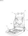
- FIG. 6 is an explanatory diagram illustrating the folded part 100 corresponding to the upper chamber 18 of the airbag 14 and illustrates the folded part 100 as viewed from the rear surface of the seatback 1.
- a folded part 100 is formed by folding the portion corresponding to the upper chamber 18 of the long rod-shaped airbag 14, and the folded part 100 is stowed above the seatback 1.
- folding and stowing in the location corresponding to the upper chamber 18 of the long rod shaped airbag 14 deployment of the folded part 100 is slightly delayed.
- the side chambers 16a and 16b that are not folded deploy first, quickly restraining movement of the occupant in the lateral direction.
- folding of the location corresponding to the upper chamber 18 enables ensuring sufficient volume of airbag above the seatback 1 to cover the head of the occupant.
- the folded part 100 (upper chamber 18) can then be deployed over the headrest 3 to cover the upper part of the occupant's head, significantly reducing the possibility of damage to the occupant's head.
- the airbag 14 compressed into the rod shape is arranged along the edge part of the seatback 1 (left edge, upper edge, and right edge) so as to reach from a first surface of the seatback 1 through the upper part and to a second surface.
- the rod shaped airbag 14 extending from the end parts in the left-right direction of the upper part of the seatback 1 toward the center in the left-right direction is folded back and extends in the direction of the end part (outside) forming first folded parts 101L and 101R.
- the airbag extends from the first folded parts 101L and 101R forming second folded parts 102L and 102R facing the center near the upper end part of the seatback 1.
- the first folded parts 101L and 101R are positioned lower than the second folded parts 102L and 102R, forming an omega shape.
- the shape of the folded part 100 is not limited to an omega shape, and may be other shapes such as an S shape.
- the folded part 100 when the folded part 100 is formed in an omega shape and the airbag 14 is deployed, the folded part 100 (18) deploys upward with a stronger force enabling the airbag 14 (upper chamber 18) to more readily ride over the headrest 3 and protrude forward, even if the headrest 3 is relatively large (tall).
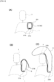
- FIG. 7(A) is an explanatory diagram illustrating the structure of a stowing part 210 used in the airbag device according to embodiment 1 of the present invention.
- FIG. 7(B) is a cross-sectional view in the direction A1-A1 of FIG. 7(A) .
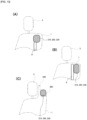
- FIG. 8(A) is an explanatory diagram illustrating the arrangement of the airbag device according to embodiment 1.
- FIG. 8(B) and FIG. 8(C) are explanatory diagrams illustrating embodiment 1 operation. Note that in FIG. 7 and FIG. 8 , the cross-section of the upper chamber 18 (100) of the airbag 14 is illustrated in a simplified manner.
- the stowing part in which the upper chamber 18 (folded part 100) of the airbag 14 is stowed is a flexible flap 210 enveloping the location corresponding to the upper chamber 18. Furthermore, a first end 210a of this flap 210 is secured to the seat frame 8 and a second end 210b extends toward the upper rear surface of the headrest 3 in conjunction with deployment of the airbag 14, thus functioning as a cover member. Note that the width W1 of the flap 210 in the left-right direction (lateral direction) is set to be equal to or greater than the width of the headrest 3.
- use of the flap 210 that envelops the upper chamber 18 (100) as a stowing part enables minimizing the space needed for the stowing part as well as storing the upper chamber 18 (folded part 100) in a relatively compact manner. Additionally, by changing the length of the flap 210, the range in the vertical direction (height direction) that can be covered by the cover member can be easily adjusted.
- FIG. 8 from a non-activated state (A), as the airbag device starts to activate, the airbag 14 expands and the upper chamber 18 starts to deploy.
- a free end 210b of the flap 210 opens based on the deployment pressure of the upper chamber 18.
- the free end 210b of the flap 210 that has opened extends toward the upper rear surface of the headrest 3 and contacts the rear surface of the headrest 3.
- the upper chamber 18 deploys along the flap 210 that functions as a cover member deploying above the head of the occupant over the headrest 3 (see FIG. 5 as well).
- FIG. 9(A) is an explanatory diagram illustrating the structure of a stowing part 220 used in the airbag device according to embodiment 2 of the present invention.
- FIG. 9(B) is a cross-sectional view in the direction A2-A2 of FIG. 9(A) .
- FIG. 10(A) is an explanatory diagram illustrating the arrangement of the airbag device according to embodiment 2.
- FIG. 10(B) and FIG. 10(C) are explanatory diagrams illustrating embodiment 2 operation. Note that in FIG. 9 and FIG. 10 , the cross-section of the upper chamber 18 (100) of the airbag 14 is illustrated in a simplified manner.
- the stowing part 220 where the upper chamber 18 (folded part 100) of the airbag 14 is stowed includes a rigid housing 222 made of metal or plastic and the housing 222 is configured so as to be secured to the seat frame 8 arranged in the seatback 1.
- the upper part of the housing 222 is provided with a lid 220a that can be opened and closed using a hinge 220b. When the airbag 14 is deployed, this lid 220a opens and functions as a cover member.
- the width W2 in the left-right direction (lateral direction) of the lid 220a can be set to be equal to or greater than the width of the headrest 3.
- using the rigid housing 222 as a stowing part causes the lid 220a to function as a cover member and this enables effectively mitigating the impact of the upper chamber 18 on the rear surface of the headrest 3 when the airbag 14 deploys.
- configuring of the cover member with a simple operation of opening and closing of the lid 220a more reliably enables the function of the cover member.
- FIG. 10 from a non-activated state (A), as the airbag device starts to activate, the airbag 14 expands and the upper chamber 18 starts to deploy.
- the lid 220a of the housing opens based on the deployment pressure of the upper chamber 18. Pressure is applied on the opened lid 220a.
- the upper chamber 18 deploys along the lid 220a that functions as a cover member deploying above the head of the occupant over the headrest 3 (see FIG. 5 ).
- FIG. 11(A) is an explanatory diagram illustrating the structure of a stowing part 230 used in the airbag device according to embodiment 3 of the present invention.
- FIG. 11(B) is a cross-sectional view in the direction A3-A3 of FIG. 11(A) .
- FIG. 12(A) is an explanatory diagram illustrating the arrangement of the airbag device according to embodiment 3.
- FIG. 12(B) and FIG. 12(C) are explanatory diagrams illustrating embodiment 3 operation. Note that in FIG. 11 and FIG. 12 , the cross-section of the upper chamber 18 (100) of the airbag 14 is illustrated in a simplified manner.
- the stowing part 230 in which the upper chamber 18 (folded part 100) of the airbag 14 is stowed, is provided with a base part 232 having a recessed part (groove or the like) 232a that is able to retain the upper chamber 18 (folded part 100) and the base part 232 is secured to the seat frame 8 arranged in the seatback 1.
- the base part 232 is provided with three flexible strip members 234a, 234b, and 234c that cover over the location (folded part 100) corresponding to the upper chamber 18 of the airbag 14.
- a first end of the strip members 234a, 234b, and 234c is secured to the base part 232 and a second end has hooks 238a, 238b, and 238c formed to engage with slits 236a, 236b, and 236c formed on the base part 232.
- the hooks 238a, 238b, and 238c of the strip members 234a, 234b, and 234c disengage causing the strip members 234a, 234b, and 234c to function as cover members.
- the overall width W3 of the three strip members 234a, 234b, and 234c can be set to be equal or greater than the width of the headrest 3.
- the base part 232 for retaining the location (folded part 100) corresponding to the upper chamber 18 of the airbag 14 being used as the stowing part 230 causes the plurality of strip members 234a, 234b, and 234c provided thereabove to function as cover members, thereby achieving the merits of both the first aspect (flap) and the second aspect (housing). In other words, this enables reliable coverage of deployment area of the airbag 14 (upper chamber 18) with a compact structure.
- FIG. 12 from a non-activated state (A), as the airbag 14 starts to activate, the upper chamber 18 starts to deploy and as illustrated in FIG. 12(B) , the hooks 238 of the strip member 234 (234a, 234b, 234c) disengage from the slit 236 due to deployment pressure of the upper chamber 18. Thereafter, as the airbag 14 fully deploys, as illustrated in FIG. 12(C) , the upper chamber 18 deploys along the strip member 234 as a cover member, deploying above the head of the occupant over the headrest 3 (see FIG. 5 ).
- FIG. 13(A), FIG. 13(B), and FIG. 13(C) are explanatory diagrams illustrating aspects where the airbag device (stowing part) according to the present invention is installed in a vehicle seat.
- the stowing parts 210, 220, and 230 are placed and secured at the upper part of the seat frame 8, or in other words, as shown in FIG. 13(B) , can be secured to the rear surface of the seat frame 8.
- a stepped part 300 for placing the stowing parts 210, 220, and 230 can be provided on the rear surface of the seatback 1.
- the stepped part 300 can be molded by processing the cushion material that makes up the seatback 1. Forming the stepped part 300 on the rear surface of the seatback 1 in this manner causes the stepped part 300 to be an upper direction reaction force surface when the upper chamber 18 of the airbag 14 is deployed enabling promoting quick deployment.
- a front wall part 302 that extends upwards can be formed on the headrest 3 side of the stepped part 300.
- the upper chamber 18 deploys upward along the front wall part 302 enabling the front wall part 302 to support (assume a part of) the cover member function.
Landscapes
- Engineering & Computer Science (AREA)
- Mechanical Engineering (AREA)
- Aviation & Aerospace Engineering (AREA)
- Transportation (AREA)
- Air Bags (AREA)
- Seats For Vehicles (AREA)
Claims (14)
- Dispositif de sac gonflable monté dans un siège de véhicule ayant un coussin de siège (2) formant une surface d'assise, un dossier de siège (1) formant un dossier, et un appui-tête (3) agencé au niveau de la partie supérieure du dossier de siège (1), comprenant :un gonfleur (12a, 12b) pour produire du gaz de gonflage ; etun sac gonflable (14) rangé au moins à l'intérieur du dossier de siège (1) qui se dilate en fonction du gaz d'expansion libéré par le gonfleur (12a, 12b), dans lequelle sac gonflable (14) comporte une paire de chambres latérales gauche et droite (16a, 16b) qui se déploient à partir des parties latérales du dossier de siège (1) vers l'avant et une chambre supérieure (18) qui est fournie en continu avec les chambres latérales (16a, 16b) et se déploie au-dessus de la tête de l'occupant,le sac gonflable (14), à partir d'un état déployé avant le rangement, est roulé ou plié et comprimé sous la forme d'une longue tige dans une direction coupant une direction longitudinale, etun emplacement du sac gonflable en forme de longue tige (14) correspondant à la chambre supérieure (18) est rangé dans une partie de rangement (210, 220, 230) pourvue dans le dossier de siège (1) sur la surface arrière de l'appui-tête (3), caractérisé parun élément de recouvrement qui se déploie vers une surface arrière de l'appui-tête (3) conjointement avec le déploiement du sac gonflable (14), dans lequell'élément de recouvrement recouvre au moins la partie limite du dossier de siège (1) et de l'appui-tête (3).
- Dispositif de sac gonflable selon la revendication 1, dans lequel
une extrémité supérieure de l'élément de recouvrement déployé atteint une extrémité supérieure de l'appui-tête (3) réglé dans la position la plus élevée de celui-ci. - Dispositif de sac gonflable selon les revendications 1 ou 2, dans lequel
une largeur latérale (W1) de l'élément de recouvrement est égale ou supérieure à une largeur de l'appui-tête (3). - Dispositif de sac gonflable selon l'une quelconque des revendications 1 à 3, dans lequel l'élément de recouvrement est un rabat flexible (210) qui enveloppe la zonecorrespondant à la chambre supérieure (18) du sac gonflable (14), etune première extrémité (210a) de ce rabat (210) est fixée et une seconde extrémité (210b) s'étend vers la partie supérieure de la surface arrière de l'appui-tête (3) conjointement avec le déploiement du sac gonflable (14).
- Dispositif de sac gonflable selon l'une quelconque des revendications 1 à 4, dans lequel la partie de rangement (210, 220, 230) comporte un boîtier rigide (222) pourranger l'emplacement correspondant à la chambre supérieure (18) du sac gonflable (14), etle boîtier est fixé à l'armature de siège agencée dans le dossier de siège (1).
- Dispositif de sac gonflable selon la revendication 5, dans lequelun couvercle (220a) qui peut être ouvert et fermé est pourvu sur la partie supérieure du boîtier, etce couvercle (220a) fonctionne comme un élément de recouvrement et s'ouvre lorsque le sac gonflable (14) se déploie.
- Dispositif de sac gonflable selon l'une quelconque des revendications 1 à 4, dans lequel la partie de rangement (210, 220, 230) comporte une partie de base (232) avec une partie évidée (232a) permettant de maintenir l'emplacement correspondant à la chambre supérieure (18) du sac gonflable (14), et
la partie de base (232) est fixée à l'armature de siège agencée dans le dossier de siège (1). - Dispositif de sac gonflable selon la revendication 7, dans lequella partie de base (232) est pourvue d'une pluralité d'éléments de bande (234a, 234b, 234c) qui recouvrent la partie supérieure de l'emplacement correspondant à la chambre supérieure (18) du sac gonflable (14),une première extrémité des éléments de bande est fixée à la partie de base (232) et une seconde extrémité vient en prise avec la partie de base (232) au moyen d'un crochet (238a, 238b, 238c), etlors du déploiement du sac gonflable (14), le crochet (238a, 238b, 238c) des éléments de bande (234a, 234b, 234c) se désolidarise et les éléments de bande (234a, 234b, 234c) fonctionnent comme un élément de recouvrement.
- Dispositif de sac gonflable selon l'une quelconque des revendications 1 à 8, dans lequell'emplacement correspondant à la chambre supérieure (18) du sac gonflable en forme de longue tige (14) est plié et formé en une partie pliée (100), etla partie pliée (100) est rangée dans la partie de rangement (210, 220, 230).
- Siège de véhicule comprenant le dispositif de sac gonflable selon l'une quelconque des revendications 1 à 9.
- Siège de véhicule selon la revendication 10, dans lequel une partie étagée (300) est pourvue dans la surface arrière du dossier de siège (1) pour placer la partie de rangement (210, 220, 230).
- Siège de véhicule selon la revendication 11, dans lequel la partie étagée (300) est moulée par traitement du matériau de coussin qui constitue le dossier de siège (1).
- Siège de véhicule selon la revendication 11 ou 12, dans lequel une partie de paroi avant (302) s'étendant vers le haut est formée du côté appui-tête de la partie étagée (300).
- Siège de véhicule selon la revendication 13, dans lequel l'élément de recouvrement s'étend au-dessus de la partie de paroi avant (302) lorsque le sac gonflable (14) est déployé.
Applications Claiming Priority (2)
| Application Number | Priority Date | Filing Date | Title |
|---|---|---|---|
| JP2019184008 | 2019-10-04 | ||
| PCT/JP2020/033193 WO2021065304A1 (fr) | 2019-10-04 | 2020-09-02 | Dispositif de coussin gonflable de sécurité et siège de véhicule |
Publications (3)
| Publication Number | Publication Date |
|---|---|
| EP4043295A1 EP4043295A1 (fr) | 2022-08-17 |
| EP4043295A4 EP4043295A4 (fr) | 2023-11-08 |
| EP4043295B1 true EP4043295B1 (fr) | 2025-04-02 |
Family
ID=75337913
Family Applications (1)
| Application Number | Title | Priority Date | Filing Date |
|---|---|---|---|
| EP20871854.4A Active EP4043295B1 (fr) | 2019-10-04 | 2020-09-02 | Dispositif de coussin gonflable de sécurité et siège de véhicule |
Country Status (6)
| Country | Link |
|---|---|
| US (1) | US11958428B2 (fr) |
| EP (1) | EP4043295B1 (fr) |
| JP (1) | JP7250156B2 (fr) |
| KR (1) | KR102675827B1 (fr) |
| CN (1) | CN114375267B (fr) |
| WO (1) | WO2021065304A1 (fr) |
Families Citing this family (7)
| Publication number | Priority date | Publication date | Assignee | Title |
|---|---|---|---|---|
| WO2019030972A1 (fr) * | 2017-08-07 | 2019-02-14 | テイ・エス テック株式会社 | Siège de véhicule |
| JP7283943B2 (ja) * | 2019-03-29 | 2023-05-30 | 株式会社Subaru | 乗員保護装置 |
| JP7165095B2 (ja) | 2019-03-29 | 2022-11-02 | 株式会社Subaru | 乗員保護装置 |
| JP7446790B2 (ja) * | 2019-11-22 | 2024-03-11 | 株式会社ダイセル | エアバッグ装置、及び車両用シート |
| CN117177886A (zh) * | 2021-04-16 | 2023-12-05 | 奥托立夫开发公司 | 安全气囊装置 |
| KR20230031555A (ko) * | 2021-08-27 | 2023-03-07 | 현대모비스 주식회사 | 차량의 시트 에어백 장치 |
| KR20230031556A (ko) * | 2021-08-27 | 2023-03-07 | 현대모비스 주식회사 | 차량의 시트 에어백 장치 |
Family Cites Families (18)
| Publication number | Priority date | Publication date | Assignee | Title |
|---|---|---|---|---|
| DE10244866B4 (de) | 2002-09-23 | 2013-10-24 | Takata Corp. | Insassenschutzeinrichtung |
| JP2007099170A (ja) * | 2005-10-06 | 2007-04-19 | Takata Corp | エアバッグ及びエアバッグ装置 |
| DE202006008373U1 (de) * | 2006-05-19 | 2006-09-14 | Takata-Petri (Ulm) Gmbh | Gassackanordnung für ein Kraftfahrzeug |
| KR20080080968A (ko) * | 2008-06-17 | 2008-09-05 | 김광부 | 자동차와 비행기용 상반신 에어백 장치 |
| JP5126132B2 (ja) | 2009-03-19 | 2013-01-23 | 豊田合成株式会社 | 側突用エアバッグ装置 |
| JP5093196B2 (ja) * | 2009-07-24 | 2012-12-05 | 豊田合成株式会社 | 側面衝突用エアバッグ装置 |
| KR101644376B1 (ko) * | 2010-01-22 | 2016-08-01 | 현대모비스 주식회사 | 후석승객보호용 정면에어백장치 |
| US20130015642A1 (en) * | 2011-07-12 | 2013-01-17 | Zodiac Aerospace | Bonnet airbag |
| JP2013124063A (ja) * | 2011-12-16 | 2013-06-24 | Toyota Motor Corp | 車両の側面衝突用ファーサイドエアバッグシステム |
| US9573553B2 (en) * | 2014-10-30 | 2017-02-21 | Hyundai Mobis Co., Ltd. | Airbag apparatus |
| JP6411965B2 (ja) * | 2015-07-28 | 2018-10-24 | トヨタ自動車株式会社 | 乗員保護装置 |
| JP6426590B2 (ja) * | 2015-12-04 | 2018-11-21 | トヨタ自動車株式会社 | 乗員保護装置 |
| JP6631369B2 (ja) | 2016-04-04 | 2020-01-15 | トヨタ自動車株式会社 | 乗員保護装置 |
| JP6442775B2 (ja) * | 2016-05-12 | 2018-12-26 | 本田技研工業株式会社 | 乗員保護装置 |
| SE541676C2 (en) * | 2016-12-22 | 2019-11-26 | Autoliv Dev | Air bag device and vehicle seat provided with an air bag device |
| JP6783715B2 (ja) | 2017-07-11 | 2020-11-11 | 本田技研工業株式会社 | エアバッグ装置 |
| EP3581441B1 (fr) * | 2018-06-13 | 2021-05-12 | Autoliv Development AB | Siège de véhicule |
| CN112339697B (zh) * | 2019-08-07 | 2023-01-13 | 奥托立夫开发公司 | 安全气囊装置 |
-
2020
- 2020-09-02 KR KR1020227014147A patent/KR102675827B1/ko active Active
- 2020-09-02 EP EP20871854.4A patent/EP4043295B1/fr active Active
- 2020-09-02 CN CN202080063633.0A patent/CN114375267B/zh active Active
- 2020-09-02 JP JP2021550468A patent/JP7250156B2/ja active Active
- 2020-09-02 US US17/754,500 patent/US11958428B2/en active Active
- 2020-09-02 WO PCT/JP2020/033193 patent/WO2021065304A1/fr not_active Ceased
Also Published As
| Publication number | Publication date |
|---|---|
| JP7250156B2 (ja) | 2023-03-31 |
| US20230242061A1 (en) | 2023-08-03 |
| EP4043295A4 (fr) | 2023-11-08 |
| CN114375267A (zh) | 2022-04-19 |
| KR102675827B1 (ko) | 2024-06-18 |
| CN114375267B (zh) | 2023-09-22 |
| US11958428B2 (en) | 2024-04-16 |
| EP4043295A1 (fr) | 2022-08-17 |
| JPWO2021065304A1 (fr) | 2021-04-08 |
| WO2021065304A1 (fr) | 2021-04-08 |
| KR20220070018A (ko) | 2022-05-27 |
Similar Documents
| Publication | Publication Date | Title |
|---|---|---|
| EP4043295B1 (fr) | Dispositif de coussin gonflable de sécurité et siège de véhicule | |
| EP4035954B1 (fr) | Dispositif coussin gonflable et siège de véhicule | |
| KR102656154B1 (ko) | 에어백 장치 | |
| JP6373547B2 (ja) | 乗員拘束システム | |
| JP7215064B2 (ja) | 乗員保護装置 | |
| EP3812221B1 (fr) | Dispositif coussin de sécurité gonflable latéral et siège de véhicule équipé de ce dernier | |
| JP7078742B2 (ja) | 車両用シート | |
| EP3744579B1 (fr) | Dispositif de coussin de sécurité gonflable latéral et siège de véhicule doté de ce dernier | |
| CN105799633B (zh) | 具有设置在座部内的安全气囊模块的车辆座椅 | |
| KR102729838B1 (ko) | 에어백 장치 및 차량용 시트 | |
| EP3772437B1 (fr) | Appareil d'airbag | |
| JP7450461B2 (ja) | エアバッグ装置 | |
| JP6183184B2 (ja) | サイドエアバッグ装置 | |
| CN116803769A (zh) | 座椅搭载型安全气囊装置 | |
| US12269409B2 (en) | Airbag device | |
| JPH0976867A (ja) | エアバッグ装置 | |
| JP2023046992A (ja) | エアバッグ装置及びエアバッグ装置を備える乗用移動体 |
Legal Events
| Date | Code | Title | Description |
|---|---|---|---|
| STAA | Information on the status of an ep patent application or granted ep patent |
Free format text: STATUS: THE INTERNATIONAL PUBLICATION HAS BEEN MADE |
|
| PUAI | Public reference made under article 153(3) epc to a published international application that has entered the european phase |
Free format text: ORIGINAL CODE: 0009012 |
|
| STAA | Information on the status of an ep patent application or granted ep patent |
Free format text: STATUS: REQUEST FOR EXAMINATION WAS MADE |
|
| 17P | Request for examination filed |
Effective date: 20220427 |
|
| AK | Designated contracting states |
Kind code of ref document: A1 Designated state(s): AL AT BE BG CH CY CZ DE DK EE ES FI FR GB GR HR HU IE IS IT LI LT LU LV MC MK MT NL NO PL PT RO RS SE SI SK SM TR |
|
| DAV | Request for validation of the european patent (deleted) | ||
| DAX | Request for extension of the european patent (deleted) | ||
| A4 | Supplementary search report drawn up and despatched |
Effective date: 20231009 |
|
| RIC1 | Information provided on ipc code assigned before grant |
Ipc: B60N 2/90 20180101ALI20231002BHEP Ipc: B60N 2/888 20180101ALI20231002BHEP Ipc: B60N 2/847 20180101ALI20231002BHEP Ipc: B60N 2/809 20180101ALI20231002BHEP Ipc: B60N 2/427 20060101ALI20231002BHEP Ipc: B60R 21/237 20060101ALI20231002BHEP Ipc: B60R 21/2338 20110101ALI20231002BHEP Ipc: B60R 21/215 20110101ALI20231002BHEP Ipc: B60R 21/207 20060101AFI20231002BHEP |
|
| GRAP | Despatch of communication of intention to grant a patent |
Free format text: ORIGINAL CODE: EPIDOSNIGR1 |
|
| STAA | Information on the status of an ep patent application or granted ep patent |
Free format text: STATUS: GRANT OF PATENT IS INTENDED |
|
| INTG | Intention to grant announced |
Effective date: 20241114 |
|
| GRAS | Grant fee paid |
Free format text: ORIGINAL CODE: EPIDOSNIGR3 |
|
| GRAA | (expected) grant |
Free format text: ORIGINAL CODE: 0009210 |
|
| STAA | Information on the status of an ep patent application or granted ep patent |
Free format text: STATUS: THE PATENT HAS BEEN GRANTED |
|
| AK | Designated contracting states |
Kind code of ref document: B1 Designated state(s): AL AT BE BG CH CY CZ DE DK EE ES FI FR GB GR HR HU IE IS IT LI LT LU LV MC MK MT NL NO PL PT RO RS SE SI SK SM TR |
|
| REG | Reference to a national code |
Ref country code: GB Ref legal event code: FG4D |
|
| REG | Reference to a national code |
Ref country code: CH Ref legal event code: EP |
|
| REG | Reference to a national code |
Ref country code: IE Ref legal event code: FG4D |
|
| REG | Reference to a national code |
Ref country code: DE Ref legal event code: R096 Ref document number: 602020048883 Country of ref document: DE |
|
| REG | Reference to a national code |
Ref country code: NL Ref legal event code: MP Effective date: 20250402 |
|
| PG25 | Lapsed in a contracting state [announced via postgrant information from national office to epo] |
Ref country code: NL Free format text: LAPSE BECAUSE OF FAILURE TO SUBMIT A TRANSLATION OF THE DESCRIPTION OR TO PAY THE FEE WITHIN THE PRESCRIBED TIME-LIMIT Effective date: 20250402 |
|
| REG | Reference to a national code |
Ref country code: AT Ref legal event code: MK05 Ref document number: 1781008 Country of ref document: AT Kind code of ref document: T Effective date: 20250402 |
|
| PG25 | Lapsed in a contracting state [announced via postgrant information from national office to epo] |
Ref country code: ES Free format text: LAPSE BECAUSE OF FAILURE TO SUBMIT A TRANSLATION OF THE DESCRIPTION OR TO PAY THE FEE WITHIN THE PRESCRIBED TIME-LIMIT Effective date: 20250402 Ref country code: FI Free format text: LAPSE BECAUSE OF FAILURE TO SUBMIT A TRANSLATION OF THE DESCRIPTION OR TO PAY THE FEE WITHIN THE PRESCRIBED TIME-LIMIT Effective date: 20250402 Ref country code: PT Free format text: LAPSE BECAUSE OF FAILURE TO SUBMIT A TRANSLATION OF THE DESCRIPTION OR TO PAY THE FEE WITHIN THE PRESCRIBED TIME-LIMIT Effective date: 20250804 |
|
| PGFP | Annual fee paid to national office [announced via postgrant information from national office to epo] |
Ref country code: DE Payment date: 20250926 Year of fee payment: 6 |
|
| REG | Reference to a national code |
Ref country code: LT Ref legal event code: MG9D |
|
| PG25 | Lapsed in a contracting state [announced via postgrant information from national office to epo] |
Ref country code: NO Free format text: LAPSE BECAUSE OF FAILURE TO SUBMIT A TRANSLATION OF THE DESCRIPTION OR TO PAY THE FEE WITHIN THE PRESCRIBED TIME-LIMIT Effective date: 20250702 Ref country code: GR Free format text: LAPSE BECAUSE OF FAILURE TO SUBMIT A TRANSLATION OF THE DESCRIPTION OR TO PAY THE FEE WITHIN THE PRESCRIBED TIME-LIMIT Effective date: 20250703 |
|
| PG25 | Lapsed in a contracting state [announced via postgrant information from national office to epo] |
Ref country code: PL Free format text: LAPSE BECAUSE OF FAILURE TO SUBMIT A TRANSLATION OF THE DESCRIPTION OR TO PAY THE FEE WITHIN THE PRESCRIBED TIME-LIMIT Effective date: 20250402 |
|
| PG25 | Lapsed in a contracting state [announced via postgrant information from national office to epo] |
Ref country code: BG Free format text: LAPSE BECAUSE OF FAILURE TO SUBMIT A TRANSLATION OF THE DESCRIPTION OR TO PAY THE FEE WITHIN THE PRESCRIBED TIME-LIMIT Effective date: 20250402 |
|
| PGFP | Annual fee paid to national office [announced via postgrant information from national office to epo] |
Ref country code: GB Payment date: 20250923 Year of fee payment: 6 |
|
| PG25 | Lapsed in a contracting state [announced via postgrant information from national office to epo] |
Ref country code: HR Free format text: LAPSE BECAUSE OF FAILURE TO SUBMIT A TRANSLATION OF THE DESCRIPTION OR TO PAY THE FEE WITHIN THE PRESCRIBED TIME-LIMIT Effective date: 20250402 |
|
| PG25 | Lapsed in a contracting state [announced via postgrant information from national office to epo] |
Ref country code: AT Free format text: LAPSE BECAUSE OF FAILURE TO SUBMIT A TRANSLATION OF THE DESCRIPTION OR TO PAY THE FEE WITHIN THE PRESCRIBED TIME-LIMIT Effective date: 20250402 |
|
| PGFP | Annual fee paid to national office [announced via postgrant information from national office to epo] |
Ref country code: FR Payment date: 20250925 Year of fee payment: 6 |
|
| PG25 | Lapsed in a contracting state [announced via postgrant information from national office to epo] |
Ref country code: RS Free format text: LAPSE BECAUSE OF FAILURE TO SUBMIT A TRANSLATION OF THE DESCRIPTION OR TO PAY THE FEE WITHIN THE PRESCRIBED TIME-LIMIT Effective date: 20250702 |
|
| PG25 | Lapsed in a contracting state [announced via postgrant information from national office to epo] |
Ref country code: IS Free format text: LAPSE BECAUSE OF FAILURE TO SUBMIT A TRANSLATION OF THE DESCRIPTION OR TO PAY THE FEE WITHIN THE PRESCRIBED TIME-LIMIT Effective date: 20250802 |
|
| PG25 | Lapsed in a contracting state [announced via postgrant information from national office to epo] |
Ref country code: LV Free format text: LAPSE BECAUSE OF FAILURE TO SUBMIT A TRANSLATION OF THE DESCRIPTION OR TO PAY THE FEE WITHIN THE PRESCRIBED TIME-LIMIT Effective date: 20250402 |
|
| REG | Reference to a national code |
Ref country code: DE Ref legal event code: R097 Ref document number: 602020048883 Country of ref document: DE |
|
| PG25 | Lapsed in a contracting state [announced via postgrant information from national office to epo] |
Ref country code: DK Free format text: LAPSE BECAUSE OF FAILURE TO SUBMIT A TRANSLATION OF THE DESCRIPTION OR TO PAY THE FEE WITHIN THE PRESCRIBED TIME-LIMIT Effective date: 20250402 Ref country code: SM Free format text: LAPSE BECAUSE OF FAILURE TO SUBMIT A TRANSLATION OF THE DESCRIPTION OR TO PAY THE FEE WITHIN THE PRESCRIBED TIME-LIMIT Effective date: 20250402 |
|
| PG25 | Lapsed in a contracting state [announced via postgrant information from national office to epo] |
Ref country code: CZ Free format text: LAPSE BECAUSE OF FAILURE TO SUBMIT A TRANSLATION OF THE DESCRIPTION OR TO PAY THE FEE WITHIN THE PRESCRIBED TIME-LIMIT Effective date: 20250402 |
|
| PG25 | Lapsed in a contracting state [announced via postgrant information from national office to epo] |
Ref country code: EE Free format text: LAPSE BECAUSE OF FAILURE TO SUBMIT A TRANSLATION OF THE DESCRIPTION OR TO PAY THE FEE WITHIN THE PRESCRIBED TIME-LIMIT Effective date: 20250402 |
|
| PG25 | Lapsed in a contracting state [announced via postgrant information from national office to epo] |
Ref country code: SK Free format text: LAPSE BECAUSE OF FAILURE TO SUBMIT A TRANSLATION OF THE DESCRIPTION OR TO PAY THE FEE WITHIN THE PRESCRIBED TIME-LIMIT Effective date: 20250402 |
|
| PG25 | Lapsed in a contracting state [announced via postgrant information from national office to epo] |
Ref country code: IT Free format text: LAPSE BECAUSE OF FAILURE TO SUBMIT A TRANSLATION OF THE DESCRIPTION OR TO PAY THE FEE WITHIN THE PRESCRIBED TIME-LIMIT Effective date: 20250402 |
|
| PLBE | No opposition filed within time limit |
Free format text: ORIGINAL CODE: 0009261 |
|
| STAA | Information on the status of an ep patent application or granted ep patent |
Free format text: STATUS: NO OPPOSITION FILED WITHIN TIME LIMIT |
|
| PG25 | Lapsed in a contracting state [announced via postgrant information from national office to epo] |
Ref country code: RO Free format text: LAPSE BECAUSE OF FAILURE TO SUBMIT A TRANSLATION OF THE DESCRIPTION OR TO PAY THE FEE WITHIN THE PRESCRIBED TIME-LIMIT Effective date: 20250402 |
|
| REG | Reference to a national code |
Ref country code: CH Ref legal event code: L10 Free format text: ST27 STATUS EVENT CODE: U-0-0-L10-L00 (AS PROVIDED BY THE NATIONAL OFFICE) Effective date: 20260211 |
|
| 26N | No opposition filed |
Effective date: 20260105 |