EP4035983A2 - Remorque de bicyclette à volume de transport variable - Google Patents
Remorque de bicyclette à volume de transport variable Download PDFInfo
- Publication number
- EP4035983A2 EP4035983A2 EP22154219.4A EP22154219A EP4035983A2 EP 4035983 A2 EP4035983 A2 EP 4035983A2 EP 22154219 A EP22154219 A EP 22154219A EP 4035983 A2 EP4035983 A2 EP 4035983A2
- Authority
- EP
- European Patent Office
- Prior art keywords
- bracket
- forehead
- connector
- forehead bracket
- sleeve
- Prior art date
- Legal status (The legal status is an assumption and is not a legal conclusion. Google has not performed a legal analysis and makes no representation as to the accuracy of the status listed.)
- Granted
Links
Images







Classifications
-
- B—PERFORMING OPERATIONS; TRANSPORTING
- B62—LAND VEHICLES FOR TRAVELLING OTHERWISE THAN ON RAILS
- B62K—CYCLES; CYCLE FRAMES; CYCLE STEERING DEVICES; RIDER-OPERATED TERMINAL CONTROLS SPECIALLY ADAPTED FOR CYCLES; CYCLE AXLE SUSPENSIONS; CYCLE SIDECARS, FORECARS, OR THE LIKE
- B62K27/00—Sidecars; Forecars; Trailers or the like specially adapted to be attached to cycles
- B62K27/003—Trailers
-
- B—PERFORMING OPERATIONS; TRANSPORTING
- B62—LAND VEHICLES FOR TRAVELLING OTHERWISE THAN ON RAILS
- B62K—CYCLES; CYCLE FRAMES; CYCLE STEERING DEVICES; RIDER-OPERATED TERMINAL CONTROLS SPECIALLY ADAPTED FOR CYCLES; CYCLE AXLE SUSPENSIONS; CYCLE SIDECARS, FORECARS, OR THE LIKE
- B62K27/00—Sidecars; Forecars; Trailers or the like specially adapted to be attached to cycles
- B62K27/02—Frames
Definitions
- bicycle trailers are often used, which usually have two wheels and are connected to the bicycle in such a way that the trailer can be towed with the bicycle.
- the advent of e-bikes in particular has made it easier to transport goods with the help of a bicycle trailer, since larger loads can also be transported without excessive effort.
- the invention is based on the object of providing a bicycle trailer whose loading volume is variable and can be easily and quickly adapted to current needs without tools, even with gloves.
- a joint for the rotatable mounting of a headband or a side wall of a bicycle trailer comprising a connector with two legs spaced apart from one another, a bearing sleeve and a fixing device, the fixing device enabling the positive locking of the headband relative to the connector in allows at least two positions, wherein the forehead bracket is rotatably mounted on the connector by means of the bearing sleeve, and wherein a clear width between the legs is greater than a diameter of the forehead bracket, so that the forehead bracket can be displaced on the bearing sleeve between the legs.
- the front bracket/tail lift can be moved on the bearing sleeve if necessary, so that a form fit between the front bracket and the connector is eliminated. Then the forehead bracket can be pivoted into another position with the bearing sleeve as the axis of rotation. The forehead bar can then be adjusted in this position by moving the forehead bar in be locked again in a form-fitting manner in the opposite direction.
- the forehead bracket is also the gripping element for the hand of an operator, no tools are required to release or engage the form fit between the forehead bracket and connector.
- This operation can also be carried out without problems in inhospitable environmental conditions (low outside temperature, rain and/or darkness) and with gloves. Repositioning the browband in a different position takes only a few seconds. Therefore, the user of the bicycle trailer makes frequent use of it and the load to be transported with the bicycle trailer is optimally accommodated in the bicycle trailer.
- the length of the trailer can be shortened so that the trailer is only as long as necessary. This is an advantage not only when driving, but also when parked.
- the connector and the joint are easy to produce in terms of manufacturing technology.
- the connector itself can be made from sheet metal produced by stamping or laser cutting by folding it twice.
- a suitable material high-strength aluminium, steel, stainless steel, ...) in connection with a suitable dimensioning, the joint is very robust, so that it can withstand tough everyday use for many years without complaint.
- the form-fitting connection or locking of the forehead bracket relative to the connector can be achieved in that a plurality of pins are fixedly arranged on the connector, these pins protruding into the space between the legs, that there is a bore in the forehead bracket, and that the form-fitting locking of the forehead bar is established, by one of the pins going into the bore of the forehead bracket when the forehead bracket is moved on the bearing sleeve.
- spring means are provided in the joint, the spring force of which presses the forehead bracket on the bearing sleeve in the direction of the leg on which the pins are fastened or in which the bores are formed.
- These spring means can be designed in a wide variety of ways. It is thus possible, for example, for the spring means to comprise a compression spring, a spring guide and a sliding sleeve, and for the compression spring to be supported at one end against the spring guide and at the other end against the sliding sleeve. It is preferred if the spring guide is accommodated in the forehead bracket and the sliding sleeve is supported against a leg of the connector. This is the leg of the connector that is positioned opposite the leg with the pins or holes.
- the compression spring it is also possible for the compression spring to be supported with one end against the sleeve and with the other end against the sliding sleeve.
- a headband with two identical joints according to the invention will be attached to the bicycle trailer. This increases the resilience of the fixation, offers redundancy and reduces the number of assemblies.
- the other joint can be designed as a completely normal joint without a fixing device.
- this joint also needs a have an axial degree of freedom, so that the forehead bracket is displaceable in the axial direction, ie parallel to the axis of rotation of the bearing sleeve.
- joints according to the invention are arranged on both longitudinal beams of the bicycle trailer, and two such joints store a forehead bracket and in one of the user of the bicycle trailer lock the desired position in a form-fitting manner.
- a front bar that can be locked according to the invention or a lockable drop side will also be provided both at the front end and at the rear end of the loading area of the bicycle trailer. This prevents the bike trailer load from sliding forwards or backwards off the loading area. At the same time, securing the load on the loading area of the bicycle trailer is simplified.
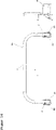
- the forehead bracket can be designed as a U-shaped pipe bend with a circular cross-section or else a square cross-section. However, it is also possible to attach a side wall to the front bar so that small objects cannot slip off the loading area under the tube bar.
- the drawbar can be attached to the actual bicycle trailer in two or more different positions. If short loads are to be transported with the bicycle trailer, the drawbar is mounted in such a way that it has a short effective length. This reduces the length of the bicycle trailer and makes it easier to drive in downtown areas or on cycle paths. If long items of cargo are to be transported, the drawbar is pulled out of the trailer as required.
- an advantage of the trailer for bicycles according to the invention is its dimensional variability; especially in length, so that the trailer can be shortened to transport loads with smaller dimensions, so that driving agility is maintained. To transport larger loads, the trailer can be extended to ensure safe transport.
- FIGS. 1 and 2 show the trailer according to the invention in the unfolded, long mode of use (FIG. 1) and once in the folded, short mode of use (FIG. 2).
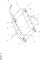
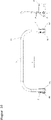
- the trailer for bicycles 1 consists of the base support 12 shown in FIG. 3, which in turn consists of the two longitudinal supports 2, the floor panel 3, and the connector 4 is possible as a stamped and bent part. Laser cutting instead of punching is also possible.
- connection of the longitudinal members 2, which are shown here, for example, in a cylindrical shape (tube), with the connector 4 takes place, for example, with the aid of the at least one screw 13, which is screwed through the bores 15 of the connector 4 shown in Figure 4, and through the bores 26 of the longitudinal member 2 shown in FIG. 5 are joined.
- the screws 13 are screwed to the nuts 17.
- the connector can also be provided with a corresponding thread.
- connection between the connectors 4 and the side members 2 can also be effected, for example, by riveting or in some other suitable manner.
- the longitudinal beams 2 are arranged in such a way that they lie between the two legs 22 of the U-shaped connector 4 .
- connection of the floor panel 3, which in a first embodiment variant, as shown in Figure 5, is designed, for example, as a sheet metal bent on the front side, with the side member 2 is carried out, for example, with the aid of the screws 14, which pass through the bores 23 and 24 of the side member 2, as well as through the holes 25 of the floor panel shown in FIG 3 are joined, the screws 14 being screwed to a nut, not shown.
- the connection between the side member 2 and the floor panel 3 can also be effected, for example, by riveting or in some other suitable manner.
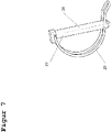
- the side brackets 6 shown in Figures 1 and 2, which are shown here for example with a circular cross section, are connected to the connectors 4 with the aid of a linch pin 27 shown in Figure 7, which consist of the pin 28 and the bracket spring 29, the bracket spring 29 is suitably connected to the pin 28 in such a way that the clip spring 29 can be rotated relative to the pin 28, and that the clip spring 29 assumes the position shown in Figure 7 relative to the pin 28 when no twisting force is exerted on the clip spring 29 .
- Linchpins in general are state of the art and are therefore not described in detail here.
- the bracket spring 29 is twisted in such a way that the pin 28 of the linch pin 28 is guided through the bore 17 in the carrier 4 and through the bore 30 in the side bracket 6 shown in Figure 8, with the side brackets 6 being positioned in such a way are arranged to lie between the two legs 22 of the connectors 4.
- the use of the linch pins 27 is primarily used for quick assembly and disassembly of the side brackets, it being possible for the side brackets 6 to be connected to the connectors 4 by screwing or riveting, for example.
- the trailer for bicycles 1 according to the invention has the drawbar 8 shown in FIGS. 1 and 2, which can be connected to the base support 12 in a detachable manner and in a number of positions.
- the drawbar 8 connects the trailer 1 according to the invention with the towing vehicle, in particular the bicycle.
- the trailer for bicycles 1 according to the invention also has the wheels 10 shown in FIGS.
- the axle 7 is connected to the base support 12 in a suitable manner.
- a fixing device 31 according to the invention is integrated in the connectors 4 .
- a first embodiment is explained with reference to FIGS. 10 to 13 and a second embodiment of the fixing device 31 according to the invention is explained with reference to FIGS.
- the forehead brackets 5 are connected to the connectors 4 in such a way that they can be rotated with respect to the connector 4 .
- the forehead brackets 5 are articulated on the connectors.
- the axis of rotation of this joint is formed by the bearing sleeve 42 in this exemplary embodiment.
- the forehead brackets 5 In order to be able to lock the forehead brackets 5 in different positions (see FIGS. 1 and 2), one of the fixing devices 31 explained below is provided in the connectors 4 .
- the forehead brackets 5 can only be twisted/folded down between the positions shown in FIGS. 1 and 2 if the fixation is released.
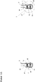
- Figure 10 shows a first embodiment of the fixing device 31 whose function is that To fix the forehead bracket 5 in the end positions shown in Figures 1 and 2.
- the forehead bracket 5 is connected to the connectors 4 via the bearing sleeve 42 in such a way that the forehead bracket 5 can rotate about the longitudinal axis of the bearing sleeve 42, with the bearing sleeve 42 protruding through the bore 18 of the connector 4 and through the bore 38 of the forehead bracket 5 . It can be secured, for example, with the screw 33 ( Figure 11).
- the bearing sleeve 42 can also be secured with the aid of a retaining ring.
- a rotatable connection of the forehead brackets 5 to the connectors 4 in another suitable manner, for example by riveting, is also conceivable.
- the end brackets 5 are arranged in such a way that they lie between the two legs 22 of the connector 4 . It is clear from FIGS. 11 and 12 that the clear width between the legs 22 is greater than the outside diameter of the forehead bracket 5.
- FIGS. 11 and 12 show the fixing device 31 in the “active” position, i. G. rotating the forehead bracket 5 is not possible.
- the connectors 4 are arranged "in the same direction". This makes it possible to move the forehead bracket 5 against the force of the compression springs 35 in the direction of the arrow Y relative to the connector. Characterized the pin 34 moves out of the bore 32 of the forehead bracket 5 and the Form closure is cancelled. Then the forehead bracket 5 can be pivoted.
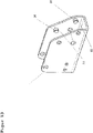
- FIG. 13 shows the connector 4 with the pins 34 and 39, the pin 34 serving to fix the forehead bracket 5 in the end position shown in FIG. 2 and the pin 39 for fixing the forehead bracket 5 in the end position shown in FIG.
- the pins 34 and 39 are inserted into the bores 19 and 21 of the connector 4 in such a way that they are axially fixed and project into the space formed by the legs 22 of the connector 4, as shown in FIGS.
- FIG. 10 and 11 show a first variant of the fixing device 31 in the fixed end position of the forehead bracket 5 shown in FIG.
- the bearing sleeve 42 and the pin 34 the forehead bracket 5 is fixed in position.
- the space formed by the legs 22 of the connector 4 is selected to be large enough for the forehead bracket 5 to be able to move in the direction marked Y in FIG.
- the compression spring 35 shown in FIGS. 10, 11 and 12 is guided in a spring guide 36, with one end of the compression spring 35 being supported on the bottom 40 of the spring guide 36.
- the spring guide 36 is accommodated in a hole in the forehead bracket 5 .
- the spring guide 36 in turn is supported with the collar 41 on the forehead bracket 5 .
- the opposite end of the compression spring 35 is supported on the connector 4 via the sliding sleeve 37 .
- the compression spring 35 generates a force on the forehead bracket 5 in the opposite direction to the direction marked Y in FIG. 10, so that the forehead bracket 5, as shown in FIGS. In In this position, there is a positive fit between the forehead bracket 5 and the connector 4.
- a compression spring 35 and a spring guide 36 and a sliding sleeve 37 are shown on both sides of the forehead bracket 5 .
- the forehead bracket 5 In order to unlock the forehead bracket 5, the forehead bracket 5 is displaced in the direction marked Y in FIG. The forehead bracket moves on the bearing sleeve 42 so that the pin 34 no longer protrudes into the bore 32 of the forehead bracket 5 when the travel distance is sufficiently large, as a result of which the forehead bracket 5 can be rotated on the bearing sleeve 42 .
- the forehead bracket 5 can be transferred from the end position shown in Figure 2 to the end position shown in Figure 1 by turning it on the bearing sleeve 42, with the sliding sleeve 37 reducing the friction between the compression spring 35 and the connector 4 and thus the time needed to turn the Forehead bracket 5 required force, and wear on the connector 4 and the compression spring 35 is reduced.
- the pin 39 shown in Figure 13 enters the bore 32 of the forehead bracket 5, as a result of which the forehead bracket 5 moves in the end position shown in Figure 1 is fixed.
- the force of the compression spring 35 prevents the forehead bracket 5 from being able to move independently in the direction marked Y in FIG. 10 and thus unlocks itself.
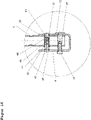
- FIG. 14 shows a second embodiment variant of the fixing device 31, the function of which is to fix the forehead brackets 5 in the end positions shown in FIGS.
- the forehead brackets 5 are connected in an articulated manner to the connectors 4 so that they can be rotated relative to the connectors 4 .
- the forehead brackets 5 can be fixed using the fixing device 31 explained below.
- the forehead brackets 5 can only be twisted relative to the connectors 4 if the fixation is released.
- the main difference from the first variant is that a sleeve 43 is guided in the forehead bracket 5, which can be displaced along the bearing sleeve 42 together with the forehead bracket 5.
- bores 21 are provided, in which the sleeve 43 engages in order to create a form fit.
- the forehead bracket 5 is connected to the connectors 4 via the bearing sleeve 42 in such a way that the forehead bracket can rotate around the bearing sleeve 42, with the bearing sleeve 42 being inserted through the bore 18 in the connectors 4 and through the bore 38 in the forehead bracket 5 and with the screw 33 is secured.
- the bearing sleeve 42 can also be secured, for example, with the aid of a securing ring.
- the end brackets 5 are arranged in such a way that they lie between the two legs 22 of the connector 4 .
- FIGS. 14, 15 and 16 show a second variant embodiment of the fixing device 31 in the fixed position shown in FIG End position of the forehead brackets 5, with the fixation taking place, as can be seen in FIGS.
- the bearing sleeve 42 and the sleeve 43 the forehead bracket 5 is fixed in its position.
- the space (clear width) formed by the legs 22 of the connector 4 is selected to be large enough for the forehead bracket 5 to be able to move in the direction indicated by the arrow "Y" in FIG.
- the compression spring 44 shown in FIGS. 14 and 15 is guided in a bore in a sleeve 43 .
- the sleeve 43 is accommodated in a hole in the forehead bracket 5 .
- One end of the compression spring 44 is supported on the bottom 46 of the sleeve 43 .
- the sleeve 43 in turn is supported with the collar 47 on the forehead bracket 5 .
- the opposite end of the compression spring 44 is supported on the connector 4 via the sliding sleeve 45 guided in the sleeve 43 .
- the compression spring 44 generates a force on the forehead bracket 5 in the opposite direction to the direction marked Y in FIG. 14, so that the forehead bracket 5, as shown in FIGS.
- a compression spring 44 and a sleeve 43 and a sliding sleeve 45 are shown on both sides of the forehead bracket 5 .
- the forehead bracket 5 In order to unlock the forehead bracket 5, the forehead bracket 5 is displaced in the direction marked Y in FIG. The forehead bracket moves on the bearing sleeve 42 so that the sleeve 43 no longer enters the bore 21 of the Connector 4 projects, as a result of which the forehead bracket 5 can be rotated on the bearing sleeve 42 .
- the forehead bracket 5 can be transferred from the end position shown in Figure 2 to the end position shown in Figure 1 by turning on the bearing sleeve 42, with the sliding sleeve 45 reducing the friction between the compression spring 44 and the connector 4 and thus the time required to turn the Forehead bracket 5 required force and wear on the connector 4 and the compression spring 44 is reduced.
- the forehead bracket is moved in the direction of the spring force, i.e. against the direction marked "Y" in Figure 14, the sleeve 43 shown in Figure 16 enters the bore 21 of the connector 4, whereby the forehead bracket 5 is fixed in the end position shown in FIG. At the same time, the force of the compression spring 44 prevents the forehead bracket 5 from being able to move independently in the direction marked "Y" in FIG. 9 and thus unlocks itself.
- Unlocking and pivoting the forehead bar 5 is very simple, requires no tools and can be easily performed even with gloves.
Landscapes
- Engineering & Computer Science (AREA)
- Transportation (AREA)
- Mechanical Engineering (AREA)
- Clamps And Clips (AREA)
- Fittings On The Vehicle Exterior For Carrying Loads, And Devices For Holding Or Mounting Articles (AREA)
- Details Of Connecting Devices For Male And Female Coupling (AREA)
Applications Claiming Priority (1)
| Application Number | Priority Date | Filing Date | Title |
|---|---|---|---|
| DE102021102362.9A DE102021102362B4 (de) | 2021-02-02 | 2021-02-02 | Fahrradanhänger mit variablem Transportvolumen |
Publications (4)
| Publication Number | Publication Date |
|---|---|
| EP4035983A2 true EP4035983A2 (fr) | 2022-08-03 |
| EP4035983A3 EP4035983A3 (fr) | 2022-10-12 |
| EP4035983C0 EP4035983C0 (fr) | 2024-01-24 |
| EP4035983B1 EP4035983B1 (fr) | 2024-01-24 |
Family
ID=80123199
Family Applications (1)
| Application Number | Title | Priority Date | Filing Date |
|---|---|---|---|
| EP22154219.4A Active EP4035983B1 (fr) | 2021-02-02 | 2022-01-31 | Remorque de bicyclette à volume de transport variable |
Country Status (2)
| Country | Link |
|---|---|
| EP (1) | EP4035983B1 (fr) |
| DE (1) | DE102021102362B4 (fr) |
Cited By (1)
| Publication number | Priority date | Publication date | Assignee | Title |
|---|---|---|---|---|
| PL441634A1 (pl) * | 2022-07-04 | 2024-01-08 | Krzysztof Gorlicki | Przyczepka rowerowa |
Family Cites Families (4)
| Publication number | Priority date | Publication date | Assignee | Title |
|---|---|---|---|---|
| US7243979B1 (en) | 2003-12-03 | 2007-07-17 | Aurora Borealis Sales & Distributing, Inc. | Recreational and utility trailer |
| DE202004017480U1 (de) | 2004-11-11 | 2006-03-16 | Oris Fahrzeugteile Hans Riehle Gmbh | Heckgepäckträger |
| DE202005010037U1 (de) | 2005-06-25 | 2005-09-08 | Leuze Electronic Gmbh & Co Kg | Vorrichtung zur Bogenkontrolle |
| DE202005010237U1 (de) | 2005-06-29 | 2005-09-29 | Gumpo Büromöbel Vertriebs- und Produktionsgesellschaft mbH | Klappbare Verbindung zwischen zwei Bauteilen |
-
2021
- 2021-02-02 DE DE102021102362.9A patent/DE102021102362B4/de active Active
-
2022
- 2022-01-31 EP EP22154219.4A patent/EP4035983B1/fr active Active
Cited By (1)
| Publication number | Priority date | Publication date | Assignee | Title |
|---|---|---|---|---|
| PL441634A1 (pl) * | 2022-07-04 | 2024-01-08 | Krzysztof Gorlicki | Przyczepka rowerowa |
Also Published As
| Publication number | Publication date |
|---|---|
| DE102021102362B4 (de) | 2022-12-15 |
| EP4035983C0 (fr) | 2024-01-24 |
| EP4035983B1 (fr) | 2024-01-24 |
| EP4035983A3 (fr) | 2022-10-12 |
| DE102021102362A1 (de) | 2022-08-04 |
Similar Documents
| Publication | Publication Date | Title |
|---|---|---|
| DE3622521A1 (de) | Sitzaufhaengungseinrichtung | |
| DE102014116771A1 (de) | Fahrradträger für ein Fahrzeug | |
| AT14443U1 (de) | Rollwagen | |
| DE2029894A1 (de) | Anhänger, insbesondere zum Transport von Gepäck auf Bahnhöfen, Flughafen o. dgl | |
| EP1727688A1 (fr) | Suspension pour une roue orientable de vehicule | |
| EP1727689A1 (fr) | Suspension pour une roue orientable de vehicule | |
| EP4035983B1 (fr) | Remorque de bicyclette à volume de transport variable | |
| EP2662261B1 (fr) | Support à roulette pour déplacer une charge | |
| EP2772372B1 (fr) | Châssis pour un véhicule utilitaire et corps d'essieu | |
| DE102019214557A1 (de) | Manteleinheit und Lenksäule für ein Kraftfahrzeug | |
| DE60017895T2 (de) | Handkarre | |
| EP3838710A1 (fr) | Chariot destiné à l'utilisation en tant que remorque de bicyclette ou chariot manuel | |
| DE19648450A1 (de) | Anhänger für Personenkraftwagen | |
| EP2543549B1 (fr) | Dispositif de support de charge, notamment pour un véhicule de transport de passagers | |
| DE20208084U1 (de) | Stützbein für Wechselbehälter-Fahrzeug | |
| EP2316673B1 (fr) | Dispositif de liaison pour un attelage ou un support de charge | |
| EP0799741B1 (fr) | Siège de véhicule automobile à assise rabattoble | |
| EP2522557B1 (fr) | Dispositif d'appui pour véhicules utilitaires et procédé de fabrication d'un dispositif d'appui pour véhicules utilitaires | |
| EP2239188A2 (fr) | Col de cygne de véhicule, notamment pour véhicule gros porteur | |
| DE69101690T2 (de) | Lenkeinrichtung für Fahrzeuge. | |
| WO2022003196A1 (fr) | Remorque de bicyclette avec barre d'attelage pivotante | |
| WO2005118332A2 (fr) | Dispositif support median de dossier | |
| DE134887C (fr) | ||
| DE202026000248U1 (de) | Kippsicherung für Einachser | |
| DE102016115998A1 (de) | Gefederter Fahrradanhänger und Federmodul für einen gefederten Fahrradanhänger |
Legal Events
| Date | Code | Title | Description |
|---|---|---|---|
| PUAI | Public reference made under article 153(3) epc to a published international application that has entered the european phase |
Free format text: ORIGINAL CODE: 0009012 |
|
| STAA | Information on the status of an ep patent application or granted ep patent |
Free format text: STATUS: THE APPLICATION HAS BEEN PUBLISHED |
|
| AK | Designated contracting states |
Kind code of ref document: A2 Designated state(s): AL AT BE BG CH CY CZ DE DK EE ES FI FR GB GR HR HU IE IS IT LI LT LU LV MC MK MT NL NO PL PT RO RS SE SI SK SM TR |
|
| PUAL | Search report despatched |
Free format text: ORIGINAL CODE: 0009013 |
|
| AK | Designated contracting states |
Kind code of ref document: A3 Designated state(s): AL AT BE BG CH CY CZ DE DK EE ES FI FR GB GR HR HU IE IS IT LI LT LU LV MC MK MT NL NO PL PT RO RS SE SI SK SM TR |
|
| RIC1 | Information provided on ipc code assigned before grant |
Ipc: B62K 27/02 20060101ALI20220908BHEP Ipc: B62K 27/00 20060101AFI20220908BHEP |
|
| STAA | Information on the status of an ep patent application or granted ep patent |
Free format text: STATUS: REQUEST FOR EXAMINATION WAS MADE |
|
| 17P | Request for examination filed |
Effective date: 20230321 |
|
| RBV | Designated contracting states (corrected) |
Designated state(s): AL AT BE BG CH CY CZ DE DK EE ES FI FR GB GR HR HU IE IS IT LI LT LU LV MC MK MT NL NO PL PT RO RS SE SI SK SM TR |
|
| GRAP | Despatch of communication of intention to grant a patent |
Free format text: ORIGINAL CODE: EPIDOSNIGR1 |
|
| STAA | Information on the status of an ep patent application or granted ep patent |
Free format text: STATUS: GRANT OF PATENT IS INTENDED |
|
| INTG | Intention to grant announced |
Effective date: 20231016 |
|
| GRAS | Grant fee paid |
Free format text: ORIGINAL CODE: EPIDOSNIGR3 |
|
| GRAA | (expected) grant |
Free format text: ORIGINAL CODE: 0009210 |
|
| STAA | Information on the status of an ep patent application or granted ep patent |
Free format text: STATUS: THE PATENT HAS BEEN GRANTED |
|
| AK | Designated contracting states |
Kind code of ref document: B1 Designated state(s): AL AT BE BG CH CY CZ DE DK EE ES FI FR GB GR HR HU IE IS IT LI LT LU LV MC MK MT NL NO PL PT RO RS SE SI SK SM TR |
|
| REG | Reference to a national code |
Ref country code: GB Ref legal event code: FG4D Free format text: NOT ENGLISH |
|
| REG | Reference to a national code |
Ref country code: CH Ref legal event code: EP |
|
| REG | Reference to a national code |
Ref country code: DE Ref legal event code: R096 Ref document number: 502022000406 Country of ref document: DE |
|
| REG | Reference to a national code |
Ref country code: IE Ref legal event code: FG4D Free format text: LANGUAGE OF EP DOCUMENT: GERMAN |
|
| U01 | Request for unitary effect filed |
Effective date: 20240131 |
|
| U07 | Unitary effect registered |
Designated state(s): AT BE BG DE DK EE FI FR IT LT LU LV MT NL PT SE SI Effective date: 20240209 |
|
| U20 | Renewal fee for the european patent with unitary effect paid |
Year of fee payment: 3 Effective date: 20240206 |
|
| PG25 | Lapsed in a contracting state [announced via postgrant information from national office to epo] |
Ref country code: IS Free format text: LAPSE BECAUSE OF FAILURE TO SUBMIT A TRANSLATION OF THE DESCRIPTION OR TO PAY THE FEE WITHIN THE PRESCRIBED TIME-LIMIT Effective date: 20240524 |
|
| PG25 | Lapsed in a contracting state [announced via postgrant information from national office to epo] |
Ref country code: GR Free format text: LAPSE BECAUSE OF FAILURE TO SUBMIT A TRANSLATION OF THE DESCRIPTION OR TO PAY THE FEE WITHIN THE PRESCRIBED TIME-LIMIT Effective date: 20240425 |
|
| PG25 | Lapsed in a contracting state [announced via postgrant information from national office to epo] |
Ref country code: HR Free format text: LAPSE BECAUSE OF FAILURE TO SUBMIT A TRANSLATION OF THE DESCRIPTION OR TO PAY THE FEE WITHIN THE PRESCRIBED TIME-LIMIT Effective date: 20240124 Ref country code: RS Free format text: LAPSE BECAUSE OF FAILURE TO SUBMIT A TRANSLATION OF THE DESCRIPTION OR TO PAY THE FEE WITHIN THE PRESCRIBED TIME-LIMIT Effective date: 20240424 |
|
| PG25 | Lapsed in a contracting state [announced via postgrant information from national office to epo] |
Ref country code: ES Free format text: LAPSE BECAUSE OF FAILURE TO SUBMIT A TRANSLATION OF THE DESCRIPTION OR TO PAY THE FEE WITHIN THE PRESCRIBED TIME-LIMIT Effective date: 20240124 |
|
| PG25 | Lapsed in a contracting state [announced via postgrant information from national office to epo] |
Ref country code: RS Free format text: LAPSE BECAUSE OF FAILURE TO SUBMIT A TRANSLATION OF THE DESCRIPTION OR TO PAY THE FEE WITHIN THE PRESCRIBED TIME-LIMIT Effective date: 20240424 Ref country code: NO Free format text: LAPSE BECAUSE OF FAILURE TO SUBMIT A TRANSLATION OF THE DESCRIPTION OR TO PAY THE FEE WITHIN THE PRESCRIBED TIME-LIMIT Effective date: 20240424 Ref country code: IS Free format text: LAPSE BECAUSE OF FAILURE TO SUBMIT A TRANSLATION OF THE DESCRIPTION OR TO PAY THE FEE WITHIN THE PRESCRIBED TIME-LIMIT Effective date: 20240524 Ref country code: HR Free format text: LAPSE BECAUSE OF FAILURE TO SUBMIT A TRANSLATION OF THE DESCRIPTION OR TO PAY THE FEE WITHIN THE PRESCRIBED TIME-LIMIT Effective date: 20240124 Ref country code: GR Free format text: LAPSE BECAUSE OF FAILURE TO SUBMIT A TRANSLATION OF THE DESCRIPTION OR TO PAY THE FEE WITHIN THE PRESCRIBED TIME-LIMIT Effective date: 20240425 Ref country code: ES Free format text: LAPSE BECAUSE OF FAILURE TO SUBMIT A TRANSLATION OF THE DESCRIPTION OR TO PAY THE FEE WITHIN THE PRESCRIBED TIME-LIMIT Effective date: 20240124 |
|
| PG25 | Lapsed in a contracting state [announced via postgrant information from national office to epo] |
Ref country code: PL Free format text: LAPSE BECAUSE OF FAILURE TO SUBMIT A TRANSLATION OF THE DESCRIPTION OR TO PAY THE FEE WITHIN THE PRESCRIBED TIME-LIMIT Effective date: 20240124 |
|
| PG25 | Lapsed in a contracting state [announced via postgrant information from national office to epo] |
Ref country code: PL Free format text: LAPSE BECAUSE OF FAILURE TO SUBMIT A TRANSLATION OF THE DESCRIPTION OR TO PAY THE FEE WITHIN THE PRESCRIBED TIME-LIMIT Effective date: 20240124 |
|
| PG25 | Lapsed in a contracting state [announced via postgrant information from national office to epo] |
Ref country code: SM Free format text: LAPSE BECAUSE OF FAILURE TO SUBMIT A TRANSLATION OF THE DESCRIPTION OR TO PAY THE FEE WITHIN THE PRESCRIBED TIME-LIMIT Effective date: 20240124 |
|
| PG25 | Lapsed in a contracting state [announced via postgrant information from national office to epo] |
Ref country code: CZ Free format text: LAPSE BECAUSE OF FAILURE TO SUBMIT A TRANSLATION OF THE DESCRIPTION OR TO PAY THE FEE WITHIN THE PRESCRIBED TIME-LIMIT Effective date: 20240124 |
|
| REG | Reference to a national code |
Ref country code: DE Ref legal event code: R097 Ref document number: 502022000406 Country of ref document: DE |
|
| PG25 | Lapsed in a contracting state [announced via postgrant information from national office to epo] |
Ref country code: SK Free format text: LAPSE BECAUSE OF FAILURE TO SUBMIT A TRANSLATION OF THE DESCRIPTION OR TO PAY THE FEE WITHIN THE PRESCRIBED TIME-LIMIT Effective date: 20240124 |
|
| PG25 | Lapsed in a contracting state [announced via postgrant information from national office to epo] |
Ref country code: SM Free format text: LAPSE BECAUSE OF FAILURE TO SUBMIT A TRANSLATION OF THE DESCRIPTION OR TO PAY THE FEE WITHIN THE PRESCRIBED TIME-LIMIT Effective date: 20240124 Ref country code: SK Free format text: LAPSE BECAUSE OF FAILURE TO SUBMIT A TRANSLATION OF THE DESCRIPTION OR TO PAY THE FEE WITHIN THE PRESCRIBED TIME-LIMIT Effective date: 20240124 Ref country code: CZ Free format text: LAPSE BECAUSE OF FAILURE TO SUBMIT A TRANSLATION OF THE DESCRIPTION OR TO PAY THE FEE WITHIN THE PRESCRIBED TIME-LIMIT Effective date: 20240124 |
|
| PG25 | Lapsed in a contracting state [announced via postgrant information from national office to epo] |
Ref country code: MC Free format text: LAPSE BECAUSE OF FAILURE TO SUBMIT A TRANSLATION OF THE DESCRIPTION OR TO PAY THE FEE WITHIN THE PRESCRIBED TIME-LIMIT Effective date: 20240124 |
|
| PG25 | Lapsed in a contracting state [announced via postgrant information from national office to epo] |
Ref country code: MC Free format text: LAPSE BECAUSE OF FAILURE TO SUBMIT A TRANSLATION OF THE DESCRIPTION OR TO PAY THE FEE WITHIN THE PRESCRIBED TIME-LIMIT Effective date: 20240124 |
|
| PLBE | No opposition filed within time limit |
Free format text: ORIGINAL CODE: 0009261 |
|
| STAA | Information on the status of an ep patent application or granted ep patent |
Free format text: STATUS: NO OPPOSITION FILED WITHIN TIME LIMIT |
|
| 26N | No opposition filed |
Effective date: 20241025 |
|
| PG25 | Lapsed in a contracting state [announced via postgrant information from national office to epo] |
Ref country code: IE Free format text: LAPSE BECAUSE OF NON-PAYMENT OF DUE FEES Effective date: 20240131 |
|
| PG25 | Lapsed in a contracting state [announced via postgrant information from national office to epo] |
Ref country code: IE Free format text: LAPSE BECAUSE OF NON-PAYMENT OF DUE FEES Effective date: 20240131 |
|
| U20 | Renewal fee for the european patent with unitary effect paid |
Year of fee payment: 4 Effective date: 20250121 |
|
| PG25 | Lapsed in a contracting state [announced via postgrant information from national office to epo] |
Ref country code: RO Free format text: LAPSE BECAUSE OF FAILURE TO SUBMIT A TRANSLATION OF THE DESCRIPTION OR TO PAY THE FEE WITHIN THE PRESCRIBED TIME-LIMIT Effective date: 20240124 |
|
| PG25 | Lapsed in a contracting state [announced via postgrant information from national office to epo] |
Ref country code: CY Free format text: LAPSE BECAUSE OF FAILURE TO SUBMIT A TRANSLATION OF THE DESCRIPTION OR TO PAY THE FEE WITHIN THE PRESCRIBED TIME-LIMIT; INVALID AB INITIO Effective date: 20220131 |
|
| REG | Reference to a national code |
Ref country code: CH Ref legal event code: PL |
|
| PG25 | Lapsed in a contracting state [announced via postgrant information from national office to epo] |
Ref country code: CH Free format text: LAPSE BECAUSE OF NON-PAYMENT OF DUE FEES Effective date: 20250131 |
|
| PG25 | Lapsed in a contracting state [announced via postgrant information from national office to epo] |
Ref country code: TR Free format text: LAPSE BECAUSE OF FAILURE TO SUBMIT A TRANSLATION OF THE DESCRIPTION OR TO PAY THE FEE WITHIN THE PRESCRIBED TIME-LIMIT Effective date: 20240124 |
|
| U20 | Renewal fee for the european patent with unitary effect paid |
Year of fee payment: 5 Effective date: 20260119 |