EP4036048A1 - Mobiles fundament für turmdrehkrane und schnellbaukrane - Google Patents
Mobiles fundament für turmdrehkrane und schnellbaukrane Download PDFInfo
- Publication number
- EP4036048A1 EP4036048A1 EP22153283.1A EP22153283A EP4036048A1 EP 4036048 A1 EP4036048 A1 EP 4036048A1 EP 22153283 A EP22153283 A EP 22153283A EP 4036048 A1 EP4036048 A1 EP 4036048A1
- Authority
- EP
- European Patent Office
- Prior art keywords
- cranes
- mobile foundation
- tower
- quick
- erecting
- Prior art date
- Legal status (The legal status is an assumption and is not a legal conclusion. Google has not performed a legal analysis and makes no representation as to the accuracy of the status listed.)
- Granted
Links
Images


Classifications
-
- B—PERFORMING OPERATIONS; TRANSPORTING
- B60—VEHICLES IN GENERAL
- B60K—ARRANGEMENT OR MOUNTING OF PROPULSION UNITS OR OF TRANSMISSIONS IN VEHICLES; ARRANGEMENT OR MOUNTING OF PLURAL DIVERSE PRIME-MOVERS IN VEHICLES; AUXILIARY DRIVES FOR VEHICLES; INSTRUMENTATION OR DASHBOARDS FOR VEHICLES; ARRANGEMENTS IN CONNECTION WITH COOLING, AIR INTAKE, GAS EXHAUST OR FUEL SUPPLY OF PROPULSION UNITS IN VEHICLES
- B60K15/00—Arrangement in connection with fuel supply of combustion engines or other fuel consuming energy converters, e.g. fuel cells; Mounting or construction of fuel tanks
- B60K15/03—Fuel tanks
-
- E—FIXED CONSTRUCTIONS
- E02—HYDRAULIC ENGINEERING; FOUNDATIONS; SOIL SHIFTING
- E02D—FOUNDATIONS; EXCAVATIONS; EMBANKMENTS; UNDERGROUND OR UNDERWATER STRUCTURES
- E02D27/00—Foundations as substructures
- E02D27/32—Foundations for special purposes
- E02D27/44—Foundations for machines, engines or ordnance
-
- B—PERFORMING OPERATIONS; TRANSPORTING
- B60—VEHICLES IN GENERAL
- B60K—ARRANGEMENT OR MOUNTING OF PROPULSION UNITS OR OF TRANSMISSIONS IN VEHICLES; ARRANGEMENT OR MOUNTING OF PLURAL DIVERSE PRIME-MOVERS IN VEHICLES; AUXILIARY DRIVES FOR VEHICLES; INSTRUMENTATION OR DASHBOARDS FOR VEHICLES; ARRANGEMENTS IN CONNECTION WITH COOLING, AIR INTAKE, GAS EXHAUST OR FUEL SUPPLY OF PROPULSION UNITS IN VEHICLES
- B60K1/00—Arrangement or mounting of electrical propulsion units
-
- B—PERFORMING OPERATIONS; TRANSPORTING
- B60—VEHICLES IN GENERAL
- B60K—ARRANGEMENT OR MOUNTING OF PROPULSION UNITS OR OF TRANSMISSIONS IN VEHICLES; ARRANGEMENT OR MOUNTING OF PLURAL DIVERSE PRIME-MOVERS IN VEHICLES; AUXILIARY DRIVES FOR VEHICLES; INSTRUMENTATION OR DASHBOARDS FOR VEHICLES; ARRANGEMENTS IN CONNECTION WITH COOLING, AIR INTAKE, GAS EXHAUST OR FUEL SUPPLY OF PROPULSION UNITS IN VEHICLES
- B60K15/00—Arrangement in connection with fuel supply of combustion engines or other fuel consuming energy converters, e.g. fuel cells; Mounting or construction of fuel tanks
- B60K15/03—Fuel tanks
- B60K15/063—Arrangement of tanks
-
- B—PERFORMING OPERATIONS; TRANSPORTING
- B60—VEHICLES IN GENERAL
- B60K—ARRANGEMENT OR MOUNTING OF PROPULSION UNITS OR OF TRANSMISSIONS IN VEHICLES; ARRANGEMENT OR MOUNTING OF PLURAL DIVERSE PRIME-MOVERS IN VEHICLES; AUXILIARY DRIVES FOR VEHICLES; INSTRUMENTATION OR DASHBOARDS FOR VEHICLES; ARRANGEMENTS IN CONNECTION WITH COOLING, AIR INTAKE, GAS EXHAUST OR FUEL SUPPLY OF PROPULSION UNITS IN VEHICLES
- B60K15/00—Arrangement in connection with fuel supply of combustion engines or other fuel consuming energy converters, e.g. fuel cells; Mounting or construction of fuel tanks
- B60K15/03—Fuel tanks
- B60K15/063—Arrangement of tanks
- B60K15/067—Mounting of tanks
-
- B—PERFORMING OPERATIONS; TRANSPORTING
- B60—VEHICLES IN GENERAL
- B60K—ARRANGEMENT OR MOUNTING OF PROPULSION UNITS OR OF TRANSMISSIONS IN VEHICLES; ARRANGEMENT OR MOUNTING OF PLURAL DIVERSE PRIME-MOVERS IN VEHICLES; AUXILIARY DRIVES FOR VEHICLES; INSTRUMENTATION OR DASHBOARDS FOR VEHICLES; ARRANGEMENTS IN CONNECTION WITH COOLING, AIR INTAKE, GAS EXHAUST OR FUEL SUPPLY OF PROPULSION UNITS IN VEHICLES
- B60K15/00—Arrangement in connection with fuel supply of combustion engines or other fuel consuming energy converters, e.g. fuel cells; Mounting or construction of fuel tanks
- B60K15/03—Fuel tanks
- B60K15/063—Arrangement of tanks
- B60K15/067—Mounting of tanks
- B60K15/07—Mounting of tanks of gas tanks
-
- B—PERFORMING OPERATIONS; TRANSPORTING
- B60—VEHICLES IN GENERAL
- B60K—ARRANGEMENT OR MOUNTING OF PROPULSION UNITS OR OF TRANSMISSIONS IN VEHICLES; ARRANGEMENT OR MOUNTING OF PLURAL DIVERSE PRIME-MOVERS IN VEHICLES; AUXILIARY DRIVES FOR VEHICLES; INSTRUMENTATION OR DASHBOARDS FOR VEHICLES; ARRANGEMENTS IN CONNECTION WITH COOLING, AIR INTAKE, GAS EXHAUST OR FUEL SUPPLY OF PROPULSION UNITS IN VEHICLES
- B60K15/00—Arrangement in connection with fuel supply of combustion engines or other fuel consuming energy converters, e.g. fuel cells; Mounting or construction of fuel tanks
- B60K15/03—Fuel tanks
- B60K15/073—Tank construction specially adapted to the vehicle
-
- B—PERFORMING OPERATIONS; TRANSPORTING
- B66—HOISTING; LIFTING; HAULING
- B66C—CRANES; LOAD-ENGAGING ELEMENTS OR DEVICES FOR CRANES, CAPSTANS, WINCHES, OR TACKLES
- B66C23/00—Cranes comprising essentially a beam, boom, or triangular structure acting as a cantilever and mounted for translatory of swinging movements in vertical or horizontal planes or a combination of such movements, e.g. jib-cranes, derricks, tower cranes
- B66C23/62—Constructional features or details
-
- E—FIXED CONSTRUCTIONS
- E04—BUILDING
- E04F—FINISHING WORK ON BUILDINGS, e.g. STAIRS, FLOORS
- E04F15/00—Flooring
- E04F15/02—Flooring or floor layers composed of a number of similar elements
- E04F15/06—Flooring or floor layers composed of a number of similar elements of metal, whether or not in combination with other material
-
- E—FIXED CONSTRUCTIONS
- E04—BUILDING
- E04H—BUILDINGS OR LIKE STRUCTURES FOR PARTICULAR PURPOSES; SWIMMING OR SPLASH BATHS OR POOLS; MASTS; FENCING; TENTS OR CANOPIES, IN GENERAL
- E04H3/00—Buildings or groups of buildings for public or similar purposes; Institutions, e.g. infirmaries or prisons
- E04H3/10—Buildings or groups of buildings for public or similar purposes; Institutions, e.g. infirmaries or prisons for meetings, entertainments, or sports
- E04H3/22—Theatres; Concert halls; Studios for broadcasting, cinematography, television or similar purposes
- E04H3/24—Constructional features of stages
- E04H3/28—Shiftable or portable platforms
-
- E—FIXED CONSTRUCTIONS
- E21—EARTH OR ROCK DRILLING; MINING
- E21B—EARTH OR ROCK DRILLING; OBTAINING OIL, GAS, WATER, SOLUBLE OR MELTABLE MATERIALS OR A SLURRY OF MINERALS FROM WELLS
- E21B15/00—Supports for the drilling machine, e.g. derricks or masts
-
- B—PERFORMING OPERATIONS; TRANSPORTING
- B60—VEHICLES IN GENERAL
- B60K—ARRANGEMENT OR MOUNTING OF PROPULSION UNITS OR OF TRANSMISSIONS IN VEHICLES; ARRANGEMENT OR MOUNTING OF PLURAL DIVERSE PRIME-MOVERS IN VEHICLES; AUXILIARY DRIVES FOR VEHICLES; INSTRUMENTATION OR DASHBOARDS FOR VEHICLES; ARRANGEMENTS IN CONNECTION WITH COOLING, AIR INTAKE, GAS EXHAUST OR FUEL SUPPLY OF PROPULSION UNITS IN VEHICLES
- B60K15/00—Arrangement in connection with fuel supply of combustion engines or other fuel consuming energy converters, e.g. fuel cells; Mounting or construction of fuel tanks
- B60K15/03—Fuel tanks
- B60K2015/03309—Tanks specially adapted for particular fuels
-
- B—PERFORMING OPERATIONS; TRANSPORTING
- B60—VEHICLES IN GENERAL
- B60K—ARRANGEMENT OR MOUNTING OF PROPULSION UNITS OR OF TRANSMISSIONS IN VEHICLES; ARRANGEMENT OR MOUNTING OF PLURAL DIVERSE PRIME-MOVERS IN VEHICLES; AUXILIARY DRIVES FOR VEHICLES; INSTRUMENTATION OR DASHBOARDS FOR VEHICLES; ARRANGEMENTS IN CONNECTION WITH COOLING, AIR INTAKE, GAS EXHAUST OR FUEL SUPPLY OF PROPULSION UNITS IN VEHICLES
- B60K15/00—Arrangement in connection with fuel supply of combustion engines or other fuel consuming energy converters, e.g. fuel cells; Mounting or construction of fuel tanks
- B60K15/03—Fuel tanks
- B60K2015/03309—Tanks specially adapted for particular fuels
- B60K2015/03315—Tanks specially adapted for particular fuels for hydrogen
-
- B—PERFORMING OPERATIONS; TRANSPORTING
- B60—VEHICLES IN GENERAL
- B60K—ARRANGEMENT OR MOUNTING OF PROPULSION UNITS OR OF TRANSMISSIONS IN VEHICLES; ARRANGEMENT OR MOUNTING OF PLURAL DIVERSE PRIME-MOVERS IN VEHICLES; AUXILIARY DRIVES FOR VEHICLES; INSTRUMENTATION OR DASHBOARDS FOR VEHICLES; ARRANGEMENTS IN CONNECTION WITH COOLING, AIR INTAKE, GAS EXHAUST OR FUEL SUPPLY OF PROPULSION UNITS IN VEHICLES
- B60K15/00—Arrangement in connection with fuel supply of combustion engines or other fuel consuming energy converters, e.g. fuel cells; Mounting or construction of fuel tanks
- B60K15/03—Fuel tanks
- B60K15/063—Arrangement of tanks
- B60K2015/0638—Arrangement of tanks the fuel tank is arranged in the rear of the vehicle
-
- B—PERFORMING OPERATIONS; TRANSPORTING
- B60—VEHICLES IN GENERAL
- B60Y—INDEXING SCHEME RELATING TO ASPECTS CROSS-CUTTING VEHICLE TECHNOLOGY
- B60Y2200/00—Type of vehicle
- B60Y2200/10—Road Vehicles
- B60Y2200/14—Trucks; Load vehicles, Busses
-
- B—PERFORMING OPERATIONS; TRANSPORTING
- B60—VEHICLES IN GENERAL
- B60Y—INDEXING SCHEME RELATING TO ASPECTS CROSS-CUTTING VEHICLE TECHNOLOGY
- B60Y2200/00—Type of vehicle
- B60Y2200/10—Road Vehicles
- B60Y2200/14—Trucks; Load vehicles, Busses
- B60Y2200/148—Semi-trailers, articulated vehicles
-
- E—FIXED CONSTRUCTIONS
- E02—HYDRAULIC ENGINEERING; FOUNDATIONS; SOIL SHIFTING
- E02D—FOUNDATIONS; EXCAVATIONS; EMBANKMENTS; UNDERGROUND OR UNDERWATER STRUCTURES
- E02D27/00—Foundations as substructures
- E02D27/32—Foundations for special purposes
- E02D27/42—Foundations for poles, masts or chimneys
Definitions
- the invention relates to a mobile foundation for tower cranes and quick-erecting cranes.
- Concrete foundations currently have to be poured for the temporary erection of tower cranes and self-erecting cranes in order to distribute the forces of the crane evenly over the subsoil via foundation anchors or foundation crosses. After completion of the construction site and dismantling of the crane, these concrete foundations have to be destroyed, loaded, transported away and disposed of.
- sidewalks and road parts are damaged by the foundation plate and the foundation anchors, which have to be repaired after the destructive removal of the concrete foundation.
- the invention solves the problem by providing a mobile foundation for tower cranes and quick-erecting cranes with the features of claim 1.
- Advantageous Embodiments of the invention are set out in the dependent claims, the description and the drawings.
- the mobile foundation according to the invention for tower cranes and quick-erecting cranes is characterized by at least two floor elements made of metal, which can be detachably connected to one another, in particular screwed together, the floor elements having anchoring devices for a crane tower.
- the floor elements are small and light enough to be transported to the construction site by truck and connected to one another there to provide the necessary support surface for a crane.
- the delivery of the modular components of the foundation can be done together with the delivery of the crane parts to the construction site, which means that no additional transport is required.
- the reusability of all parts of the foundation according to the invention reduces the costs enormously compared to conventional concrete foundations that can only be used once.
- the floor elements can preferably be connected to one another at their side walls, in that the side walls have through-holes for screws, with the positions of the through-holes in the side walls of the floor elements corresponding to one another. This allows the floor members to be placed side by side and the through holes in the side walls of the floor members to be aligned with each other. The floor elements are then connected to each other with screws and nuts.
- each floor element comprises supports that are connected to one another, in particular welded.
- the desired high strength and rigidity is achieved in particular if at least some of the beams are designed as H-beams or T-beams.
- the strength and rigidity of the floor elements can be further increased if the floor elements have cover plates and/or base plates which are connected to at least some of the beams.
- the cover plates and/or base plates can have recesses. These recesses also facilitate access to the side walls of the floor elements, around adjacently arranged floor elements on their mutually facing side walls to connect with each other. It is also expedient if the cover plates and/or base plates have the anchoring devices for a crane tower.
- the invention provides that the mobile foundation has transportable ballast weights and at least one bearing surface for has the transportable ballast weights.
- the ballast weights can be brought to the construction site by truck and placed on the supporting surface of the mobile foundation on site, which ensures easy assembly and dismantling of the mobile foundation.
- a preferred embodiment of the invention provides a passage element with uprights and/or side walls, with the clear height between the Uprights or side walls have a height of at least 2.1 m, preferably at least 2.3 m, wherein the passage element can be releasably connected to the floor elements, in particular screwed.
- the passage element has supports connecting the uprights to one another at their upper end, with the supports forming a support for transportable ballast weights.
- the uprights carry a cover plate at their upper end, the cover plate forming a support for transportable ballast weights.
- the cover plate can be connected directly to the uprights, or to the supports mentioned.
- the cover plate can also contribute to the structural rigidity and strength of the passage element.
- the ballast weights placed on the passage element can also offer protection for pedestrians.
- the height of the floor elements should be as small as possible.
- the invention therefore provides that floor elements of the foundation have a maximum height of 70 cm, preferably a maximum of 50 cm, more preferably a maximum of 40 cm.
- the foundation has ramp elements that can be releasably connected to the floor elements in the region of the passage element, the width of which corresponds at least to the clear width of the passage element.
- the passage element continuously usable.
- stair elements can also be provided to bridge the height difference between the underground and the floor of the passage element.
- the floor elements and the passage element are preferably made of steel.
- the anchoring devices for the crane tower have through holes or threaded holes in the floor elements and, if necessary, mechanical safeguards against unscrewing nuts, or holding elements fastened to the floor elements, in particular clamps, include.
- Illustrated embodiment of the mobile foundation according to the invention for tower cranes and self-erecting cranes comprises two floor elements 2, 3 made of metal, which can be releasably connected to one another, in particular screwed together.
- the floor elements have anchoring devices 4 for a crane tower 5 .
- the anchoring devices 4 for the crane tower 5 are designed as through-holes, optionally with mechanical safeguards to prevent nuts from being unscrewed, but can alternatively also include retaining elements, in particular clamps, fastened to the floor elements 2, 3.
- the crane tower 5 is not part of the present invention, but part of a tower crane or quick-erecting crane for which the mobile foundation 1 forms a temporary foundation.
- the floor elements 2, 3 have side walls 2a, 3a on which they can be connected to one another.
- through-holes 6 are provided in the side walls 2a, 3a, the positions of the through-holes 6 in the side walls 2a, 3a of the base elements 2, 3 corresponding to one another, so that when the side walls 2a, 3a are arranged side-by-side Bottom elements 2, 3, the through-holes 6 can be brought into alignment with one another, in order to then detachably connect the side walls 2a, 3a to one another with screws or bolts passed through the through-holes 6.
- the floor elements 2, 3 comprise beams 7 which are connected to one another, in particular welded. At least some of the beams 7 can be designed as H-beams or T-beams.
- the floor elements 2, 3 have cover plates 8 and base plates 9, which are connected to at least some of the supports 7.
- the cover plates 8 and base plates 9 can be welded to vertically arranged plates or I-beams.
- the cover plates 8 have recesses 8a.
- the anchoring devices 4 for the crane tower 5 are formed in the cover plates 8 . This results in a uniform distribution of the forces introduced from the crane tower 5 into the foundation 1 on the ground.
- the mobile foundation 1 for tower cranes and self-erecting cranes includes a passage element 10 with vertical uprights 11.
- the passage element 10 can be designed with side walls (not shown in the drawings).
- the clear height between the uprights 11 or side walls is at least 2.1 m, preferably at least 2.3 m.
- the uprights 11 are connected to one another at their upper end with supports 12, e.g. H-supports.
- additional struts not shown in the drawing, can be provided.
- the carriers 12 form a support for transportable, reusable ballast weights 13, which are used to weigh down the mobile foundation 1.
- ballast weights 13 can also be placed on the floor elements 2 , 3 , in particular the cover plates 8 .
- the stability of the crane on the foundation 1 is ensured by these reusable ballast elements 13.
- the passage element 10 can be screwed to the base element 2 . So that pedestrians can easily step through the passage element 10, the floor elements 2, 3 are designed with a maximum height of 50 cm, preferably a maximum of 40 cm. In order to make the passage element 10 also usable for prams, wheelchairs, etc., stepless accessibility is provided in that the foundation 1 is provided with ramp elements, not shown in the drawings, arranged laterally to the floor elements 2, 3 in the area of the passage element 10. The width of the ramp elements should be at least as large as the clear width of the passage element 10.
- the floor elements 2, 3 and the components of the passage element 10 preferably consist of steel parts of the required quality.
Landscapes
- Engineering & Computer Science (AREA)
- Life Sciences & Earth Sciences (AREA)
- Mechanical Engineering (AREA)
- Architecture (AREA)
- Transportation (AREA)
- Combustion & Propulsion (AREA)
- Chemical & Material Sciences (AREA)
- Civil Engineering (AREA)
- Structural Engineering (AREA)
- Mining & Mineral Resources (AREA)
- Sustainable Energy (AREA)
- Sustainable Development (AREA)
- General Life Sciences & Earth Sciences (AREA)
- General Engineering & Computer Science (AREA)
- Paleontology (AREA)
- Geology (AREA)
- Fluid Mechanics (AREA)
- Environmental & Geological Engineering (AREA)
- Physics & Mathematics (AREA)
- Multimedia (AREA)
- Geochemistry & Mineralogy (AREA)
- Conveying And Assembling Of Building Elements In Situ (AREA)
- Foundations (AREA)
- Jib Cranes (AREA)
Abstract
Description
- Die Erfindung betrifft ein mobiles Fundament für Turmdrehkrane und Schnellbaukrane.
- Derzeit müssen für die temporäre Errichtung von Turmdrehkranen und Schnellbaukranen Betonfundamente gegossen werden, um über Fundamentanker oder Fundamentkreuze die Kräfte des Kranes gleichmäßig auf den Untergrund zu verteilen. Diese Betonfundamente müssen nach Fertigstellung der Baustelle und Abbau des Krans zerstört, verladen, abtransportiert und entsorgt werden.
- Diese Art der Errichtung von Kranfundamenten ist sowohl unwirtschaftlich als auch ökologisch äußerst fragwürdig, wenn man bedenkt, dass die Herstellung von 1 m3 Beton mit ca. 1000 kg CO2 Belastung für die Umwelt verbunden ist und die Fundamentplatte eines mittelgroßen Kranes typischerweise aus 20-40 m3 Stahlbeton besteht und nur einmal verwendbar ist.
- Weiters werden durch die Fundamentplatte und die Fundamentanker Gehsteige und Straßenteile beschädigt, die nach der zerstörenden Entfernung des Betonfundaments wiederinstandgesetzt werden müssen.
- Ein weiterer Nachteil herkömmlicher Kranfundamente aus Beton besteht darin, dass die Betonfundamente Höhen von 75-150 cm erfordern, um die nötige Festigkeit und Verteilung der Kranlasten zu gewähren. Solch hohe Betonfundamente versperren aber die Gehsteige, d.h. der Fußgängerverkehr muss auf die Straße oder die gegenüberliegende Straßenseite verlagert werden. Auch der Fahrzeugverkehr wird durch notwendige Fahrspurverengungen oder Fahrspurschließungen beeinträchtigt.
- Es ist die Aufgabe der vorliegenden Erfindung, die beschriebenen Nachteile der bekannten Kranfundamente aus Beton zu überwinden. Insbesondere ist es die Aufgabe der vorliegenden Erfindung, auf die herkömmlichen Betonfundamente, Fundamentanker bzw. Fundamentkreuze verzichten zu können.
- Die Erfindung löst die gestellte Aufgabe durch Bereitstellen eines mobilen Fundaments für Turmdrehkrane und Schnellbaukrane mit den Merkmalen des Anspruchs 1. Vorteilhafte Ausführungsformen der Erfindung sind in den Unteransprüchen, der Beschreibung und den Zeichnungen dargelegt.
- Das erfindungsgemäße mobile Fundament für Turmdrehkrane und Schnellbaukrane zeichnet sich durch zumindest zwei Bodenelemente aus Metall aus, die miteinander lösbar verbindbar, insbesondere miteinander verschraubbar sind, wobei die Bodenelemente Verankerungsvorrichtungen für einen Kranturm aufweisen.
- Durch die modulare Bauweise des Fundaments sind die Bodenelemente klein und leicht genug, um mittels LKW zur Baustelle gebracht und dort miteinander verbunden zu werden, um die nötige Auflagefläche für einen Kran bereitzustellen. Die Anlieferung der modularen Bestandteile des Fundaments kann zusammen mit der Anlieferung der Kranteile zur Baustelle erfolgen, wodurch kein zusätzlicher Transport erforderlich ist.
- Die Wiederverwendbarkeit aller Teile des erfindungsgemäßen Fundaments verringert die Kosten gegenüber den nur einmal verwendbaren, herkömmlichen Betonfundamenten enorm.
- Bevorzugt sind die Bodenelemente an ihren Seitenwänden miteinander verbindbar, indem die Seitenwände Durchgangslöcher für Schrauben aufweisen, wobei die Positionen der Durchgangslöcher in den Seitenwänden der Bodenelemente einander entsprechen. Dadurch können die Bodenelemente Seite-an-Seite angeordnet werden und die Durchgangslöcher in den Seitenwänden der Bodenelemente miteinander in Ausrichtung gebracht werden. Anschließend werden die Bodenelemente durch Schrauben und Muttern miteinander verbunden.
- Um Bodenelemente mit geringem Gewicht, aber hoher Festigkeit und Steifigkeit bereitzustellen, ist in einer Ausführungsform der Erfindung vorgesehen, dass jedes Bodenelement miteinander verbundene, insbesondere verschweißte, Träger umfasst. Die gewünschte hohe Festigkeit und Steifigkeit erreicht man insbesondere, wenn zumindest einige der Träger als H-Träger oder T-Träger ausgebildet sind.
- Die Festigkeit und Steifigkeit der Bodenelemente kann weiter erhöht werden, wenn die Bodenelemente Deckplatten und/oder Grundplatten aufweisen, die mit zumindest einigen der Träger verbunden sind. Um das Gewicht der Bodenelemente gering zu halten, können die Deckplatten und/oder Grundplatten Ausnehmungen aufweisen. Diese Ausnehmungen erleichtern auch die Zugänglichkeit zu den Seitenwänden der Bodenelemente, um benachbart angeordnete Bodenelemente an ihren einander zugewandten Seitenwänden miteinander zu verbinden. Es ist weiters zweckmäßig, wenn die Deckplatten und/oder Grundplatten die Verankerungsvorrichtungen für einen Kranturm aufweisen.
- Um das erfindungsgemäße mobile Fundament für Turmdrehkrane und Schnellbaukrane trotz seines vergleichsweise geringen Gewichts ausreichend stabil gegenüber Windlasten und Kran-Nutzlasten zu machen, die auf einen am Fundament montierten Kran einwirken, sieht die Erfindung vor, dass das mobile Fundament transportable Ballastgewichte und zumindest eine Auflagefläche für die transportablen Ballastgewichte aufweist. Die Ballastgewichte können mit dem LKW zur Baustelle gebracht und vor Ort auf die Auflagefläche des mobilen Fundaments aufgelegt werden, wodurch ein einfacher Aufbau und Abbau des mobilen Fundaments gewährleistet ist.
- Um Gehsteige einerseits als Auflagefläche für das mobile Fundament für Turmdrehkrane und Schnellbaukrane zu nutzen und andererseits diese Gehsteige weiterhin für den Fußgängerverkehr offen zu halten, ist in einer bevorzugten Ausführungsform der Erfindung ein Durchgangselement mit Stehern und/oder Seitenwänden vorgesehen, wobei die lichte Höhe zwischen den Stehern bzw. Seitenwänden eine Höhe von zumindest 2,1 m, vorzugsweise von zumindest 2,3 m, aufweist, wobei das Durchgangselement mit den Bodenelementen lösbar verbindbar, insbesondere verschraubbar ist. Um das Durchgangselement möglichst steif und fest auszubilden, ist vorgesehen, dass das Durchgangselement die Steher an ihrem oberen Ende miteinander verbindende Träger aufweist, wobei die Träger eine Auflage für transportable Ballastgewichte bilden. Um das Durchgangselement durchschreitende Fußgänger vor herabfallenden Teilen, Schmutz oder Regenwasser zu schützen, ist es zweckmäßig, wenn die Steher an ihrem oberen Ende eine Deckplatte tragen, wobei die Deckplatte eine Auflage für transportable Ballastgewichte bildet. Die Deckplatte kann direkt mit den Stehern verbunden sein, oder mit den genannten Trägern. Die Deckplatte kann auch zur konstruktiven Steifigkeit und Festigkeit des Durchgangselements beitragen. Als Alternative zur Deckplatte können auch die auf das Durchgangselement aufgelegten Ballastgewichte Schutz für Fußgänger bieten.
- Damit das Durchgangselement praktisch nutzbar ist, sollte die Höhe der Bodenelemente möglichst gering sein. Die Erfindung sieht daher in einer Ausführungsform vor, dass Bodenelemente des Fundaments eine Höhe von maximal 70 cm, vorzugsweise von maximal 50 cm, noch bevorzugter von maximal 40 cm, aufweisen. Zusätzlich ist es zweckmäßig, wenn das Fundament mit den Bodenelementen im Bereich des Durchgangselements lösbar verbindbare Rampenelemente aufweist, deren Breite zumindest der lichten Breite des Durchgangselements entspricht. Durch diese Maßnahme ist das Durchgangselement stufenlos benutzbar. Alternativ zu Rampenelementen können auch Treppenelemente zur Überbrückung des Höhenunterschieds zwischen dem Untergrund und dem Boden des Durchgangselements vorgesehen sein.
- Bevorzugt bestehen die Bodenelemente und das Durchgangselement aus Stahl.
- Für rasche und sichere Montage eines Kranturms am erfindungsgemäßen mobilen Fundament für Turmdrehkrane und Schnellbaukrane ist es zweckmäßig, wenn die Verankerungsvorrichtungen für den Kranturm Durchgangslöcher oder Gewindelöcher in den Bodenelementen und gegebenenfalls mechanische Sicherungen gegen Herausdrehen von Muttern, oder an den Bodenelementen befestigte Halteelemente, insbesondere Klammern, umfassen.
- Die Erfindung wird nun anhand eines Ausführungsbeispiels unter Bezugnahme auf die Zeichnungen näher erläutert. In den Zeichnungen zeigen:
-
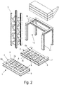
Fig. 1 undFig. 2 schematische perspektivische Ansichten der wesentlichen Bestandteile des erfindungsgemäßen mobilen Fundaments für Turmdrehkrane und Schnellbaukrane; -
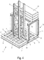
Fig. 3 undFig. 4 schematische perspektivische Ansichten des erfindungsgemäßen mobilen Fundaments für Turmdrehkrane und Schnellbaukrane im zusammengebauten Zustand. - Das in den
Figuren 1 bis 4 dargestellte Ausführungsbeispiel des erfindungsgemäßen mobilen Fundaments für Turmdrehkrane und Schnellbaukrane umfasst zwei Bodenelemente 2, 3 aus Metall, die miteinander lösbar verbindbar, insbesondere miteinander verschraubbar sind. Die Bodenelemente weisen Verankerungsvorrichtungen 4 für einen Kranturm 5 auf. Die Verankerungsvorrichtungen 4 für den Kranturm 5 sind als Durchgangslöcher, optional mit mechanischen Sicherungen gegen Herausdrehen von Muttern ausgebildet, können alternativ dazu jedoch auch an den Bodenelementen 2, 3 befestigte Halteelemente, insbesondere Klammern, umfassen. Der Kranturm 5 ist nicht Bestandteil der vorliegenden Erfindung, sondern Bestandteil eines Turmdrehkranes oder Schnellbaukranes, für den das mobile Fundament 1 ein temporäres Fundament bildet. - Die Bodenelemente 2, 3 weisen Seitenwände 2a, 3a auf, an denen sie miteinander verbindbar sind. Dazu sind in den Seitenwänden 2a, 3a Durchgangslöcher 6 vorgesehen, wobei die Positionen der Durchgangslöcher 6 in den Seitenwänden 2a, 3a der Bodenelemente 2, 3 einander entsprechen, sodass bei Seite-an-Seite-Anordnung der Seitenwände 2a, 3a der Bodenelemente 2, 3 die Durchgangslöcher 6 miteinander in Ausrichtung bringbar sind, um anschließend die Seitenwände 2a, 3a mit durch die Durchgangslöcher 6 hindurchgeführten Schrauben oder Bolzen lösbar miteinander zu verbinden. Die Bodenelemente 2, 3 umfassen miteinander verbundene, insbesondere verschweißte, Träger 7. Zumindest einige der Träger 7 können als H-Träger oder T-Träger ausgebildet sein. Weiters weisen die Bodenelemente 2, 3 Deckplatten 8 und Grundplatten 9 auf, die mit zumindest einigen der Träger 7 verbunden sind. Anstelle der Ausbildung von H-Trägern oder T-Trägern können die Deckplatten 8 und Grundplatten 9 mit vertikal angeordneten Platten oder I-Trägern verschweißt sein. Zur Gewichtseinsparung weisen die Deckplatten 8 Ausnehmungen 8a auf. Die Verankerungsvorrichtungen 4 für den Kranturm 5 sind in den Deckplatten 8 ausgebildet. Dadurch ergibt sich eine gleichmäßige Verteilung der vom Kranturm 5 in das Fundament 1 eingeleiteten Kräfte auf den Untergrund.
- Weiters umfasst das mobile Fundament 1 für Turmdrehkrane und Schnellbaukrane ein Durchgangselement 10 mit vertikalen Stehern 11. Als Alternative oder ergänzend zu den Stehern 11 kann das Durchgangselemente 10 mit (in den Zeichnungen nicht dargestellten) Seitenwänden ausgebildet sein. Die lichte Höhe zwischen den Stehern 11 bzw. Seitenwänden beträgt zumindest 2,1 m, vorzugsweise zumindest 2,3 m. Die Steher 11 sind an ihrem oberen Ende miteinander mit Trägern 12, z.B. H-Träger, verbunden. Zur Erhöhung der Festigkeit und Stabilität können zusätzlich, in der Zeichnung nicht dargestellte, Verstrebungen vorgesehen werden. Die Träger 12 bilden eine Auflage für transportable, wiederverwendbare Ballastgewichte 13, die zur Beschwerung des mobilen Fundaments 1 dienen. Ergänzend oder alternativ dazu können Ballastgewichte 13 auch auf den Bodenelementen 2, 3, insbesondere den Deckplatten 8 aufgelegt werden. Die Stabilität des Kranes auf dem Fundament 1 wird durch diese wiederverwendbaren Ballastelemente 13 gewährleistet.
- Das Durchgangselement 10 ist mit dem Bodenelement 2 verschraubbar. Damit das Durchgangselement 10 ohne Mühe von Fußgängern durchschritten werden kann, sind die Bodenelemente 2, 3 mit einer Höhe von maximal 50 cm, vorzugsweise von maximal 40 cm, ausgebildet. Um das Durchgangselement 10 auch für Kinderwagen, Rollstühle etc. benutzbar zu machen, ist eine stufenlose Befahrbarkeit vorgesehen, indem das Fundament 1 seitlich von den Bodenelementen 2, 3 mit im Bereich des Durchgangselements 10 angeordneten, in den Zeichnungen nicht dargestellten, Rampenelementen versehen ist. Die Breite der Rampenelemente soll zumindest so groß sein wie die lichte Breite des Durchgangselements 10.
- Bevorzugt bestehen die Bodenelemente 2, 3 und die Bestandteile des Durchgangselements 10 aus Stahlteilen in der erforderlichen Güte.
Claims (16)
- Mobiles Fundament (1) für Turmdrehkrane und Schnellbaukrane, gekennzeichnet durch zumindest zwei Bodenelemente (2, 3) aus Metall, die miteinander lösbar verbindbar, insbesondere miteinander verschraubbar sind, wobei die Bodenelemente (2, 3) Verankerungsvorrichtungen (4) für einen Kranturm (5) aufweisen.
- Mobiles Fundament für Turmdrehkrane und Schnellbaukrane nach Anspruch 1, dadurch gekennzeichnet, dass die Bodenelemente (2, 3) an ihren Seitenwänden (2a, 3a) miteinander verbindbar sind, indem die Seitenwände (2a, 3a) Durchgangslöcher (6) für Schrauben aufweisen, wobei die Positionen der Durchgangslöcher (6) in den Seitenwänden (2a, 3a) der Bodenelemente (2, 3) einander entsprechen und somit bei Seite-an-Seite-Anordnung der Bodenelemente (2, 3) miteinander in Ausrichtung bringbar sind.
- Mobiles Fundament für Turmdrehkrane und Schnellbaukrane nach Anspruch 1 oder 2, dadurch gekennzeichnet, dass jedes Bodenelement (2, 3) miteinander verbundene, insbesondere verschweißte, Träger (7) umfasst.
- Mobiles Fundament für Turmdrehkrane und Schnellbaukrane nach Anspruch 3, dadurch gekennzeichnet, dass zumindest einige der Träger (7) als H-Träger oder T-Träger ausgebildet sind.
- Mobiles Fundament für Turmdrehkrane und Schnellbaukrane nach Anspruch 3 oder 4, dadurch gekennzeichnet, dass die Bodenelemente (2, 3) Deckplatten (8) und/oder Grundplatten (9) aufweisen, die mit zumindest einigen der Träger (7) verbunden sind.
- Mobiles Fundament für Turmdrehkrane und Schnellbaukrane nach Anspruch 5, dadurch gekennzeichnet, dass die Deckplatten (8) und/oder Grundplatten (9) Ausnehmungen (8a) aufweisen.
- Mobiles Fundament für Turmdrehkrane und Schnellbaukrane nach Anspruch 5 oder 6, dadurch gekennzeichnet, dass die Deckplatten (8) und/oder Grundplatten (9) die Verankerungsvorrichtungen (4) für einen Kranturm (5) aufweisen.
- Mobiles Fundament für Turmdrehkrane und Schnellbaukrane nach einem der vorhergehenden Ansprüche, dadurch gekennzeichnet, dass das mobile Fundament (1) transportable Ballastgewichte (13) und zumindest eine Auflagefläche für die transportablen Ballastgewichte (13) aufweist.
- Mobiles Fundament für Turmdrehkrane und Schnellbaukrane nach einem der vorhergehenden Ansprüche, dadurch gekennzeichnet, dass ein Durchgangselement (10) mit Stehern (11) und/oder Seitenwänden vorgesehen ist, wobei die lichte Höhe zwischen den Stehern (11) bzw. Seitenwänden eine Höhe von zumindest 2,1 m, vorzugsweise von zumindest 2,3 m, aufweist, wobei das Durchgangselement (10) mit den Bodenelementen (2, 3) lösbar verbindbar, insbesondere verschraubbar ist.
- Mobiles Fundament für Turmdrehkrane und Schnellbaukrane nach Anspruch 9, dadurch gekennzeichnet, dass das Durchgangselement (10) die Steher (11) an ihrem oberen Ende miteinander verbindende Träger (12) und optional zusätzliche Verstrebungen aufweist, wobei die Träger (12) eine Auflage für transportable Ballastgewichte (13) bilden.
- Mobiles Fundament für Turmdrehkrane und Schnellbaukrane nach Anspruch 9 oder 10, dadurch gekennzeichnet, dass die Steher (11) an ihrem oberen Ende eine Deckplatte tragen, wobei die Deckplatte eine Auflage für transportable Ballastgewichte (13) bildet.
- Mobiles Fundament für Turmdrehkrane und Schnellbaukrane nach einem der vorhergehenden Ansprüche, dadurch gekennzeichnet, dass Bodenelemente (2, 3) eine Höhe von maximal 70 cm, vorzugsweise von maximal 50 cm, noch bevorzugter von maximal 40 cm, aufweisen.
- Mobiles Fundament für Turmdrehkrane und Schnellbaukrane nach einem der Ansprüche 9 bis 12, dadurch gekennzeichnet, dass das Fundament (1) mit den Bodenelementen (2, 3) im Bereich des Durchgangselements (10) lösbar verbindbare Rampen- oder Treppenelemente aufweist, deren Breite zumindest der lichten Breite des Durchgangselements (10) entspricht.
- Mobiles Fundament für Turmdrehkrane und Schnellbaukrane nach einem der vorhergehenden Ansprüche, dadurch gekennzeichnet, dass die Bodenelemente (2, 3) aus Stahl bestehen.
- Mobiles Fundament für Turmdrehkrane und Schnellbaukrane nach einem der Ansprüche 9 bis 14, dadurch gekennzeichnet, dass das Durchgangselement (10) aus Stahl besteht.
- Mobiles Fundament für Turmdrehkrane und Schnellbaukrane nach einem der vorhergehenden Ansprüche, dadurch gekennzeichnet, dass die Verankerungsvorrichtungen (4) für den Kranturm (5) Durchgangslöcher oder Gewindelöcher in den Bodenelementen (2, 3) und gegebenenfalls mechanische Sicherungen gegen Herausdrehen von Muttern, oder an den Bodenelementen (2, 3) befestigte Halteelemente, insbesondere Klammern, umfassen.
Applications Claiming Priority (1)
| Application Number | Priority Date | Filing Date | Title |
|---|---|---|---|
| ATA50061/2021A AT524735B1 (de) | 2021-02-01 | 2021-02-01 | Mobiles Fundament für Turmdrehkrane und Schnellbaukrane |
Publications (3)
| Publication Number | Publication Date |
|---|---|
| EP4036048A1 true EP4036048A1 (de) | 2022-08-03 |
| EP4036048C0 EP4036048C0 (de) | 2025-08-20 |
| EP4036048B1 EP4036048B1 (de) | 2025-08-20 |
Family
ID=80035102
Family Applications (1)
| Application Number | Title | Priority Date | Filing Date |
|---|---|---|---|
| EP22153283.1A Active EP4036048B1 (de) | 2021-02-01 | 2022-01-25 | Mobiles fundament für turmdrehkrane und schnellbaukrane |
Country Status (5)
| Country | Link |
|---|---|
| US (1) | US12227913B2 (de) |
| EP (1) | EP4036048B1 (de) |
| AT (1) | AT524735B1 (de) |
| CA (1) | CA3146585A1 (de) |
| ES (1) | ES3053412T3 (de) |
Families Citing this family (1)
| Publication number | Priority date | Publication date | Assignee | Title |
|---|---|---|---|---|
| AT524735B1 (de) * | 2021-02-01 | 2025-10-15 | Kainzmayer Thomas | Mobiles Fundament für Turmdrehkrane und Schnellbaukrane |
Citations (3)
| Publication number | Priority date | Publication date | Assignee | Title |
|---|---|---|---|---|
| EP2481853A1 (de) * | 2011-01-27 | 2012-08-01 | Liebherr-Werk Biberach GmbH | Fundamentverankerung für Arbeitsmaschine |
| US20120255256A1 (en) * | 2011-04-06 | 2012-10-11 | Big Astor S.R.L. | Modular pedestrian tunnel |
| CN108729465A (zh) * | 2018-05-31 | 2018-11-02 | 东北电力大学 | 一种基于模块化预制的装配式塔吊基础及其搭建方法 |
Family Cites Families (13)
| Publication number | Priority date | Publication date | Assignee | Title |
|---|---|---|---|---|
| US4759162A (en) * | 1987-04-16 | 1988-07-26 | Wyse Steven J | Modular platform assembly |
| CN201850558U (zh) * | 2010-03-12 | 2011-06-01 | 合肥学院 | 一种装配式钢结构塔式起重机基础 |
| CN202346643U (zh) * | 2011-11-09 | 2012-07-25 | 冯保玉 | 组合式塔吊基座 |
| US9447643B2 (en) * | 2013-09-20 | 2016-09-20 | Cenovus Energy Inc. | Drilling rig equipment platform |
| AU2016102095B4 (en) * | 2015-12-08 | 2018-05-10 | United Rentals Australia Pty Ltd | Modular gantry structure |
| CN207003465U (zh) * | 2017-05-27 | 2018-02-13 | 绍兴文理学院 | 一种可拆卸式预制钢体塔吊基础 |
| US10233059B1 (en) * | 2017-09-15 | 2019-03-19 | Greenfield Products, Llc | Crane mat system and method |
| CN209353366U (zh) * | 2018-11-13 | 2019-09-06 | 中国建筑第八工程局有限公司 | 塔吊基础转换件 |
| CN209923966U (zh) * | 2019-03-11 | 2020-01-10 | 浙江大学城市学院 | 可自由调节角度和位置的装配式钢结构塔吊基础承台 |
| US11591802B1 (en) * | 2020-02-28 | 2023-02-28 | Material Control, Inc. | Modular access system |
| CN111321754B (zh) * | 2020-04-08 | 2024-11-29 | 浙江大学城市学院 | 一种装配式钢结构塔吊基础承台 |
| CN111663558A (zh) * | 2020-06-30 | 2020-09-15 | 刘信君 | 万能装配式设备基础 |
| AT524735B1 (de) * | 2021-02-01 | 2025-10-15 | Kainzmayer Thomas | Mobiles Fundament für Turmdrehkrane und Schnellbaukrane |
-
2021
- 2021-02-01 AT ATA50061/2021A patent/AT524735B1/de active
-
2022
- 2022-01-24 CA CA3146585A patent/CA3146585A1/en active Pending
- 2022-01-24 US US17/648,720 patent/US12227913B2/en active Active
- 2022-01-25 EP EP22153283.1A patent/EP4036048B1/de active Active
- 2022-01-25 ES ES22153283T patent/ES3053412T3/es active Active
Patent Citations (3)
| Publication number | Priority date | Publication date | Assignee | Title |
|---|---|---|---|---|
| EP2481853A1 (de) * | 2011-01-27 | 2012-08-01 | Liebherr-Werk Biberach GmbH | Fundamentverankerung für Arbeitsmaschine |
| US20120255256A1 (en) * | 2011-04-06 | 2012-10-11 | Big Astor S.R.L. | Modular pedestrian tunnel |
| CN108729465A (zh) * | 2018-05-31 | 2018-11-02 | 东北电力大学 | 一种基于模块化预制的装配式塔吊基础及其搭建方法 |
Also Published As
| Publication number | Publication date |
|---|---|
| EP4036048C0 (de) | 2025-08-20 |
| EP4036048B1 (de) | 2025-08-20 |
| AT524735A1 (de) | 2022-08-15 |
| US20220243419A1 (en) | 2022-08-04 |
| AT524735B1 (de) | 2025-10-15 |
| CA3146585A1 (en) | 2022-08-01 |
| US12227913B2 (en) | 2025-02-18 |
| ES3053412T3 (en) | 2026-01-22 |
Similar Documents
| Publication | Publication Date | Title |
|---|---|---|
| DE602005002760T2 (de) | Windkraftanlageturm, vorgefertigtes metallisches Wandteil zum Gebrauch in diesem Turm, und Verfahren zur Herstellung dieses Turms | |
| DE60309668T2 (de) | Windkraftanlage | |
| AT521432B1 (de) | Fundament für ein Windkraftwerk | |
| EP3821084B1 (de) | Fundament für ein windkraftwerk | |
| AT517959B1 (de) | Fundament für ein Windrad | |
| DE102008055607A1 (de) | Verfahren zum Errichten eines segmentierten Turms aus Spannbeton für Windkraftanlagen und Turm für Windkraftanlagen | |
| EP1631722A2 (de) | Fundament für eine windenergieanlage | |
| DE102019109503A1 (de) | Fundament für eine Windkraftanlage | |
| DE102018112857A1 (de) | Fundament für eine Windkraftanlage | |
| EP3208405B1 (de) | Vorrichtung und verfahren zur errichtung von turmartigen bauwerken aus fertigteilelementen | |
| DE112022001701T5 (de) | Korbförmige Stahlkastenbogenbrücke im Schwalbenstil mit großer Spannweite und speziell geformten Bogenrippen und ihre schnelle Konstruktionsmethode | |
| CH714893A2 (de) | Fahrbares Arbeitsgerüst. | |
| DE202015003668U1 (de) | Unterbau für einen Mast und Mastsystem | |
| EP4036048B1 (de) | Mobiles fundament für turmdrehkrane und schnellbaukrane | |
| DE102007047919B4 (de) | Traggerüst und Verfahren zur Demontage und Transport | |
| DE102010025869A1 (de) | Brückenentlastungs- und Brückenertüchtigungsgerät | |
| EP2977529A1 (de) | Punktfundament | |
| DE202008008396U1 (de) | Solartraggestelle mit Fundamenten | |
| DE60112332T2 (de) | Laststütze und entsprechende stützbasis, die im hoch- und tiefbau und in gebäuden verwendet werden | |
| WO2022069348A1 (de) | Fundament für eine windkraftanlage | |
| DE102019126587A1 (de) | Fundament für eine Windkraftanlage | |
| DE102014118543B4 (de) | Abgrenzungsanordnung | |
| DE102019126629A1 (de) | Fundament für eine Windkraftanlage | |
| DE2212898C3 (de) | Großflächige Brückenplattform aus Ortbeton und Bauverfahren zu deren Herstellung | |
| DE29619816U1 (de) | Zerlegbarer und versetzbarer, modulartig aufgebauter Kleinkran zum Einsatz auf Baustellen |
Legal Events
| Date | Code | Title | Description |
|---|---|---|---|
| PUAI | Public reference made under article 153(3) epc to a published international application that has entered the european phase |
Free format text: ORIGINAL CODE: 0009012 |
|
| STAA | Information on the status of an ep patent application or granted ep patent |
Free format text: STATUS: THE APPLICATION HAS BEEN PUBLISHED |
|
| AK | Designated contracting states |
Kind code of ref document: A1 Designated state(s): AL AT BE BG CH CY CZ DE DK EE ES FI FR GB GR HR HU IE IS IT LI LT LU LV MC MK MT NL NO PL PT RO RS SE SI SK SM TR |
|
| STAA | Information on the status of an ep patent application or granted ep patent |
Free format text: STATUS: REQUEST FOR EXAMINATION WAS MADE |
|
| 17P | Request for examination filed |
Effective date: 20230116 |
|
| RAX | Requested extension states of the european patent have changed |
Extension state: ME Payment date: 20230116 Extension state: BA Payment date: 20230116 |
|
| RBV | Designated contracting states (corrected) |
Designated state(s): AL AT BE BG CH CY CZ DE DK EE ES FI FR GB GR HR HU IE IS IT LI LT LU LV MC MK MT NL NO PL PT RO RS SE SI SK SM TR |
|
| STAA | Information on the status of an ep patent application or granted ep patent |
Free format text: STATUS: EXAMINATION IS IN PROGRESS |
|
| 17Q | First examination report despatched |
Effective date: 20240524 |
|
| GRAP | Despatch of communication of intention to grant a patent |
Free format text: ORIGINAL CODE: EPIDOSNIGR1 |
|
| STAA | Information on the status of an ep patent application or granted ep patent |
Free format text: STATUS: GRANT OF PATENT IS INTENDED |
|
| INTG | Intention to grant announced |
Effective date: 20250321 |
|
| GRAS | Grant fee paid |
Free format text: ORIGINAL CODE: EPIDOSNIGR3 |
|
| GRAA | (expected) grant |
Free format text: ORIGINAL CODE: 0009210 |
|
| STAA | Information on the status of an ep patent application or granted ep patent |
Free format text: STATUS: THE PATENT HAS BEEN GRANTED |
|
| AK | Designated contracting states |
Kind code of ref document: B1 Designated state(s): AL AT BE BG CH CY CZ DE DK EE ES FI FR GB GR HR HU IE IS IT LI LT LU LV MC MK MT NL NO PL PT RO RS SE SI SK SM TR |
|
| REG | Reference to a national code |
Ref country code: GB Ref legal event code: FG4D Free format text: NOT ENGLISH |
|
| REG | Reference to a national code |
Ref country code: CH Ref legal event code: EP |
|
| REG | Reference to a national code |
Ref country code: IE Ref legal event code: FG4D Free format text: LANGUAGE OF EP DOCUMENT: GERMAN |
|
| REG | Reference to a national code |
Ref country code: DE Ref legal event code: R096 Ref document number: 502022005073 Country of ref document: DE |
|
| U01 | Request for unitary effect filed |
Effective date: 20250911 |
|
| U07 | Unitary effect registered |
Designated state(s): AT BE BG DE DK EE FI FR IT LT LU LV MT NL PT RO SE SI Effective date: 20250916 |
|
| REG | Reference to a national code |
Ref country code: CH Ref legal event code: R17 Free format text: ST27 STATUS EVENT CODE: U-0-0-R10-R17 (AS PROVIDED BY THE NATIONAL OFFICE) Effective date: 20251113 |
|
| PG25 | Lapsed in a contracting state [announced via postgrant information from national office to epo] |
Ref country code: IS Free format text: LAPSE BECAUSE OF FAILURE TO SUBMIT A TRANSLATION OF THE DESCRIPTION OR TO PAY THE FEE WITHIN THE PRESCRIBED TIME-LIMIT Effective date: 20251220 |
|
| PG25 | Lapsed in a contracting state [announced via postgrant information from national office to epo] |
Ref country code: HR Free format text: LAPSE BECAUSE OF FAILURE TO SUBMIT A TRANSLATION OF THE DESCRIPTION OR TO PAY THE FEE WITHIN THE PRESCRIBED TIME-LIMIT Effective date: 20250820 |
|
| PG25 | Lapsed in a contracting state [announced via postgrant information from national office to epo] |
Ref country code: GR Free format text: LAPSE BECAUSE OF FAILURE TO SUBMIT A TRANSLATION OF THE DESCRIPTION OR TO PAY THE FEE WITHIN THE PRESCRIBED TIME-LIMIT Effective date: 20251121 |
|
| REG | Reference to a national code |
Ref country code: ES Ref legal event code: FG2A Ref document number: 3053412 Country of ref document: ES Kind code of ref document: T3 Effective date: 20260122 |
|
| PG25 | Lapsed in a contracting state [announced via postgrant information from national office to epo] |
Ref country code: RS Free format text: LAPSE BECAUSE OF FAILURE TO SUBMIT A TRANSLATION OF THE DESCRIPTION OR TO PAY THE FEE WITHIN THE PRESCRIBED TIME-LIMIT Effective date: 20251120 |
|
| REG | Reference to a national code |
Ref country code: CH Ref legal event code: U11 Free format text: ST27 STATUS EVENT CODE: U-0-0-U10-U11 (AS PROVIDED BY THE NATIONAL OFFICE) Effective date: 20260201 |
|
| U20 | Renewal fee for the european patent with unitary effect paid |
Year of fee payment: 5 Effective date: 20260127 |
|
| PG25 | Lapsed in a contracting state [announced via postgrant information from national office to epo] |
Ref country code: SM Free format text: LAPSE BECAUSE OF FAILURE TO SUBMIT A TRANSLATION OF THE DESCRIPTION OR TO PAY THE FEE WITHIN THE PRESCRIBED TIME-LIMIT Effective date: 20250820 |
|
| PGFP | Annual fee paid to national office [announced via postgrant information from national office to epo] |
Ref country code: GB Payment date: 20260122 Year of fee payment: 5 |
|
| PGFP | Annual fee paid to national office [announced via postgrant information from national office to epo] |
Ref country code: ES Payment date: 20260217 Year of fee payment: 5 |
|
| PGFP | Annual fee paid to national office [announced via postgrant information from national office to epo] |
Ref country code: NO Payment date: 20260120 Year of fee payment: 5 Ref country code: IE Payment date: 20260121 Year of fee payment: 5 |
|
| PG25 | Lapsed in a contracting state [announced via postgrant information from national office to epo] |
Ref country code: CZ Free format text: LAPSE BECAUSE OF FAILURE TO SUBMIT A TRANSLATION OF THE DESCRIPTION OR TO PAY THE FEE WITHIN THE PRESCRIBED TIME-LIMIT Effective date: 20250820 |
|
| PGFP | Annual fee paid to national office [announced via postgrant information from national office to epo] |
Ref country code: CH Payment date: 20260201 Year of fee payment: 5 |
|
| PGFP | Annual fee paid to national office [announced via postgrant information from national office to epo] |
Ref country code: PL Payment date: 20260122 Year of fee payment: 5 |
|
| PG25 | Lapsed in a contracting state [announced via postgrant information from national office to epo] |
Ref country code: SK Free format text: LAPSE BECAUSE OF FAILURE TO SUBMIT A TRANSLATION OF THE DESCRIPTION OR TO PAY THE FEE WITHIN THE PRESCRIBED TIME-LIMIT Effective date: 20250820 |