EP4036192A1 - Verfahren zur herstellung von gereinigtem gas, verfahren zur herstellung von wertstoffen, gasreinigungsvorrichtung und vorrichtung zur herstellung von wertstoffen - Google Patents
Verfahren zur herstellung von gereinigtem gas, verfahren zur herstellung von wertstoffen, gasreinigungsvorrichtung und vorrichtung zur herstellung von wertstoffen Download PDFInfo
- Publication number
- EP4036192A1 EP4036192A1 EP20869003.2A EP20869003A EP4036192A1 EP 4036192 A1 EP4036192 A1 EP 4036192A1 EP 20869003 A EP20869003 A EP 20869003A EP 4036192 A1 EP4036192 A1 EP 4036192A1
- Authority
- EP
- European Patent Office
- Prior art keywords
- gas
- raw material
- impurity
- material gas
- solid
- Prior art date
- Legal status (The legal status is an assumption and is not a legal conclusion. Google has not performed a legal analysis and makes no representation as to the accuracy of the status listed.)
- Pending
Links
Images





Classifications
-
- B—PERFORMING OPERATIONS; TRANSPORTING
- B01—PHYSICAL OR CHEMICAL PROCESSES OR APPARATUS IN GENERAL
- B01D—SEPARATION
- B01D53/00—Separation of gases or vapours; Recovering vapours of volatile solvents from gases; Chemical or biological purification of waste gases, e.g. engine exhaust gases, smoke, fumes, flue gases, aerosols
- B01D53/02—Separation of gases or vapours; Recovering vapours of volatile solvents from gases; Chemical or biological purification of waste gases, e.g. engine exhaust gases, smoke, fumes, flue gases, aerosols by adsorption, e.g. preparative gas chromatography
- B01D53/04—Separation of gases or vapours; Recovering vapours of volatile solvents from gases; Chemical or biological purification of waste gases, e.g. engine exhaust gases, smoke, fumes, flue gases, aerosols by adsorption, e.g. preparative gas chromatography with stationary adsorbents
- B01D53/047—Pressure swing adsorption
-
- C—CHEMISTRY; METALLURGY
- C10—PETROLEUM, GAS OR COKE INDUSTRIES; TECHNICAL GASES CONTAINING CARBON MONOXIDE; FUELS; LUBRICANTS; PEAT
- C10K—PURIFYING OR MODIFYING THE CHEMICAL COMPOSITION OF COMBUSTIBLE GASES CONTAINING CARBON MONOXIDE
- C10K1/00—Purifying combustible gases containing carbon monoxide
- C10K1/04—Purifying combustible gases containing carbon monoxide by cooling to condense non-gaseous materials
-
- B—PERFORMING OPERATIONS; TRANSPORTING
- B01—PHYSICAL OR CHEMICAL PROCESSES OR APPARATUS IN GENERAL
- B01D—SEPARATION
- B01D53/00—Separation of gases or vapours; Recovering vapours of volatile solvents from gases; Chemical or biological purification of waste gases, e.g. engine exhaust gases, smoke, fumes, flue gases, aerosols
- B01D53/002—Separation of gases or vapours; Recovering vapours of volatile solvents from gases; Chemical or biological purification of waste gases, e.g. engine exhaust gases, smoke, fumes, flue gases, aerosols by condensation
-
- B—PERFORMING OPERATIONS; TRANSPORTING
- B01—PHYSICAL OR CHEMICAL PROCESSES OR APPARATUS IN GENERAL
- B01D—SEPARATION
- B01D53/00—Separation of gases or vapours; Recovering vapours of volatile solvents from gases; Chemical or biological purification of waste gases, e.g. engine exhaust gases, smoke, fumes, flue gases, aerosols
- B01D53/02—Separation of gases or vapours; Recovering vapours of volatile solvents from gases; Chemical or biological purification of waste gases, e.g. engine exhaust gases, smoke, fumes, flue gases, aerosols by adsorption, e.g. preparative gas chromatography
- B01D53/04—Separation of gases or vapours; Recovering vapours of volatile solvents from gases; Chemical or biological purification of waste gases, e.g. engine exhaust gases, smoke, fumes, flue gases, aerosols by adsorption, e.g. preparative gas chromatography with stationary adsorbents
- B01D53/047—Pressure swing adsorption
- B01D53/0476—Vacuum pressure swing adsorption
-
- C—CHEMISTRY; METALLURGY
- C07—ORGANIC CHEMISTRY
- C07C—ACYCLIC OR CARBOCYCLIC COMPOUNDS
- C07C29/00—Preparation of compounds having hydroxy or O-metal groups bound to a carbon atom not belonging to a six-membered aromatic ring
- C07C29/15—Preparation of compounds having hydroxy or O-metal groups bound to a carbon atom not belonging to a six-membered aromatic ring by reduction of oxides of carbon exclusively
- C07C29/151—Preparation of compounds having hydroxy or O-metal groups bound to a carbon atom not belonging to a six-membered aromatic ring by reduction of oxides of carbon exclusively with hydrogen or hydrogen-containing gases
- C07C29/1516—Multisteps
- C07C29/1518—Multisteps one step being the formation of initial mixture of carbon oxides and hydrogen for synthesis
-
- C—CHEMISTRY; METALLURGY
- C10—PETROLEUM, GAS OR COKE INDUSTRIES; TECHNICAL GASES CONTAINING CARBON MONOXIDE; FUELS; LUBRICANTS; PEAT
- C10K—PURIFYING OR MODIFYING THE CHEMICAL COMPOSITION OF COMBUSTIBLE GASES CONTAINING CARBON MONOXIDE
- C10K1/00—Purifying combustible gases containing carbon monoxide
- C10K1/002—Removal of contaminants
- C10K1/003—Removal of contaminants of acid contaminants, e.g. acid gas removal
- C10K1/005—Carbon dioxide
-
- C—CHEMISTRY; METALLURGY
- C10—PETROLEUM, GAS OR COKE INDUSTRIES; TECHNICAL GASES CONTAINING CARBON MONOXIDE; FUELS; LUBRICANTS; PEAT
- C10K—PURIFYING OR MODIFYING THE CHEMICAL COMPOSITION OF COMBUSTIBLE GASES CONTAINING CARBON MONOXIDE
- C10K1/00—Purifying combustible gases containing carbon monoxide
- C10K1/02—Dust removal
-
- C—CHEMISTRY; METALLURGY
- C10—PETROLEUM, GAS OR COKE INDUSTRIES; TECHNICAL GASES CONTAINING CARBON MONOXIDE; FUELS; LUBRICANTS; PEAT
- C10K—PURIFYING OR MODIFYING THE CHEMICAL COMPOSITION OF COMBUSTIBLE GASES CONTAINING CARBON MONOXIDE
- C10K1/00—Purifying combustible gases containing carbon monoxide
- C10K1/02—Dust removal
- C10K1/024—Dust removal by filtration
-
- C—CHEMISTRY; METALLURGY
- C10—PETROLEUM, GAS OR COKE INDUSTRIES; TECHNICAL GASES CONTAINING CARBON MONOXIDE; FUELS; LUBRICANTS; PEAT
- C10K—PURIFYING OR MODIFYING THE CHEMICAL COMPOSITION OF COMBUSTIBLE GASES CONTAINING CARBON MONOXIDE
- C10K1/00—Purifying combustible gases containing carbon monoxide
- C10K1/04—Purifying combustible gases containing carbon monoxide by cooling to condense non-gaseous materials
- C10K1/06—Purifying combustible gases containing carbon monoxide by cooling to condense non-gaseous materials combined with spraying with water
-
- C—CHEMISTRY; METALLURGY
- C10—PETROLEUM, GAS OR COKE INDUSTRIES; TECHNICAL GASES CONTAINING CARBON MONOXIDE; FUELS; LUBRICANTS; PEAT
- C10K—PURIFYING OR MODIFYING THE CHEMICAL COMPOSITION OF COMBUSTIBLE GASES CONTAINING CARBON MONOXIDE
- C10K1/00—Purifying combustible gases containing carbon monoxide
- C10K1/32—Purifying combustible gases containing carbon monoxide with selectively adsorptive solids, e.g. active carbon
-
- B—PERFORMING OPERATIONS; TRANSPORTING
- B01—PHYSICAL OR CHEMICAL PROCESSES OR APPARATUS IN GENERAL
- B01D—SEPARATION
- B01D2253/00—Adsorbents used in seperation treatment of gases and vapours
- B01D2253/10—Inorganic adsorbents
- B01D2253/102—Carbon
-
- B—PERFORMING OPERATIONS; TRANSPORTING
- B01—PHYSICAL OR CHEMICAL PROCESSES OR APPARATUS IN GENERAL
- B01D—SEPARATION
- B01D2253/00—Adsorbents used in seperation treatment of gases and vapours
- B01D2253/10—Inorganic adsorbents
- B01D2253/106—Silica or silicates
- B01D2253/108—Zeolites
-
- B—PERFORMING OPERATIONS; TRANSPORTING
- B01—PHYSICAL OR CHEMICAL PROCESSES OR APPARATUS IN GENERAL
- B01D—SEPARATION
- B01D2257/00—Components to be removed
- B01D2257/50—Carbon oxides
- B01D2257/504—Carbon dioxide
-
- B—PERFORMING OPERATIONS; TRANSPORTING
- B01—PHYSICAL OR CHEMICAL PROCESSES OR APPARATUS IN GENERAL
- B01D—SEPARATION
- B01D2257/00—Components to be removed
- B01D2257/55—Compounds of silicon, phosphorus, germanium or arsenic
- B01D2257/556—Organic compounds
-
- C—CHEMISTRY; METALLURGY
- C10—PETROLEUM, GAS OR COKE INDUSTRIES; TECHNICAL GASES CONTAINING CARBON MONOXIDE; FUELS; LUBRICANTS; PEAT
- C10J—PRODUCTION OF PRODUCER GAS, WATER-GAS, SYNTHESIS GAS FROM SOLID CARBONACEOUS MATERIAL, OR MIXTURES CONTAINING THESE GASES; CARBURETTING AIR OR OTHER GASES
- C10J2300/00—Details of gasification processes
- C10J2300/09—Details of the feed, e.g. feeding of spent catalyst, inert gas or halogens
- C10J2300/0913—Carbonaceous raw material
- C10J2300/0916—Biomass
-
- C—CHEMISTRY; METALLURGY
- C10—PETROLEUM, GAS OR COKE INDUSTRIES; TECHNICAL GASES CONTAINING CARBON MONOXIDE; FUELS; LUBRICANTS; PEAT
- C10J—PRODUCTION OF PRODUCER GAS, WATER-GAS, SYNTHESIS GAS FROM SOLID CARBONACEOUS MATERIAL, OR MIXTURES CONTAINING THESE GASES; CARBURETTING AIR OR OTHER GASES
- C10J2300/00—Details of gasification processes
- C10J2300/09—Details of the feed, e.g. feeding of spent catalyst, inert gas or halogens
- C10J2300/0913—Carbonaceous raw material
- C10J2300/0946—Waste, e.g. MSW, tires, glass, tar sand, peat, paper, lignite, oil shale
-
- C—CHEMISTRY; METALLURGY
- C10—PETROLEUM, GAS OR COKE INDUSTRIES; TECHNICAL GASES CONTAINING CARBON MONOXIDE; FUELS; LUBRICANTS; PEAT
- C10J—PRODUCTION OF PRODUCER GAS, WATER-GAS, SYNTHESIS GAS FROM SOLID CARBONACEOUS MATERIAL, OR MIXTURES CONTAINING THESE GASES; CARBURETTING AIR OR OTHER GASES
- C10J2300/00—Details of gasification processes
- C10J2300/16—Integration of gasification processes with another plant or parts within the plant
- C10J2300/164—Integration of gasification processes with another plant or parts within the plant with conversion of synthesis gas
- C10J2300/1656—Conversion of synthesis gas to chemicals
- C10J2300/1665—Conversion of synthesis gas to chemicals to alcohols, e.g. methanol or ethanol
-
- C—CHEMISTRY; METALLURGY
- C10—PETROLEUM, GAS OR COKE INDUSTRIES; TECHNICAL GASES CONTAINING CARBON MONOXIDE; FUELS; LUBRICANTS; PEAT
- C10J—PRODUCTION OF PRODUCER GAS, WATER-GAS, SYNTHESIS GAS FROM SOLID CARBONACEOUS MATERIAL, OR MIXTURES CONTAINING THESE GASES; CARBURETTING AIR OR OTHER GASES
- C10J2300/00—Details of gasification processes
- C10J2300/16—Integration of gasification processes with another plant or parts within the plant
- C10J2300/1681—Integration of gasification processes with another plant or parts within the plant with biological plants, e.g. involving bacteria, algae, fungi
-
- C—CHEMISTRY; METALLURGY
- C12—BIOCHEMISTRY; BEER; SPIRITS; WINE; VINEGAR; MICROBIOLOGY; ENZYMOLOGY; MUTATION OR GENETIC ENGINEERING
- C12P—FERMENTATION OR ENZYME-USING PROCESSES TO SYNTHESISE A DESIRED CHEMICAL COMPOUND OR COMPOSITION OR TO SEPARATE OPTICAL ISOMERS FROM A RACEMIC MIXTURE
- C12P7/00—Preparation of oxygen-containing organic compounds
- C12P7/02—Preparation of oxygen-containing organic compounds containing a hydroxy group
- C12P7/04—Preparation of oxygen-containing organic compounds containing a hydroxy group acyclic
- C12P7/06—Ethanol, i.e. non-beverage
- C12P7/08—Ethanol, i.e. non-beverage produced as by-product or from waste or cellulosic material substrate
Definitions
- the present invention relates to a method for producing a purified gas, comprising removing an impurity contained in a raw material gas derived from a waste, a method for producing a valuable material, a gas purification apparatus, and an apparatus for producing a valuable material.
- a technology for gasifying various wastes such as an industrial waste and a general waste by thermal decomposition is known (see, for example, PTL 1).
- a raw material gas including large amounts of carbon monoxide and hydrogen can be obtained by thermally decomposing a waste.
- a waste-derived raw material gas can be used for various applications, and for example, it has been attempted to convert such a raw material gas into a valuable material such as ethanol by using a microbial catalyst, a metal catalyst, or the like (see, for example, PTL 2).
- a waste-derived raw material gas includes a phase transitioning impurity that can phase transition between the gas phase and the solid phase, including a sublimating substance such as naphthalene, 1-naphthol, and 2-naphthol, when a substance including a large amount of a non-carbon component such as a municipal solid waste (MSW) is gasified.
- a phase transitioning impurity that can phase transition between the gas phase and the solid phase, including a sublimating substance such as naphthalene, 1-naphthol, and 2-naphthol, when a substance including a large amount of a non-carbon component such as a municipal solid waste (MSW) is gasified.
- This type of phase transitioning impurity even if it is initially gas phase when generated in a waste treatment facility, may be changed into solid-phase depending on the temperature conditions of the mainstream and the like and adhere to a filter installed in the mainstream and thereby cause the filter to be clogged. Because of this, the filter
- a waste-derived raw material gas includes a large amount of water, and when the raw material gas is cooled at once in order to remove the water and the phase transitioning impurity, the solid-phased phase transitioning impurity and a liquid-phased impurity such as soot and tar will be captured by the filter, causing the filter to be severely clogged. For this reason, in order to separately remove the water and the phase transitioning impurity in the raw material gas, a method involving carrying out a cooling step of the raw material gas in two stages has been proposed (see, for example, PTL 3).
- the present invention has been made in view of the above conventional problems, and an object thereof is to provide a method for producing a purified gas, which, when a valuable material is generated from a waste-derived raw material gas, can efficiently remove a phase transitioning impurity contained in the raw material gas, a method for producing a valuable material, a gas purification apparatus, and an apparatus for producing a valuable material.
- the present inventor has found that the above problem can be solved by removing a phase transitioning impurity in the raw material gas by a pressure swing adsorption apparatus combined with a vacuum pump, and completed the present invention described below. That is, the present invention provides the following [1] to [18].
- a method for producing a purified gas which, when a valuable material is generated from a waste-derived raw material gas, can efficiently remove a phase transitioning impurity contained in the raw material gas, a method for producing a valuable material, a gas purification apparatus, and an apparatus for producing a valuable material can be provided.
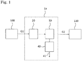
- a gas purification apparatus 1a according to a first embodiment of the present invention is provided in connection with a raw material gas generation facility 100 and a valuable material generation reaction unit 110.
- the raw material gas generation facility 100 is a facility that generates a raw material gas G1, which is a waste-derived gas.
- the raw material gas G1 generated by the raw material gas generation facility 100 is introduced into the gas purification apparatus 1a.
- the gas purification apparatus 1a is a facility that removes an impurity contained in the raw material gas G1 introduced to generate a purified gas G2.
- the purified gas G2 generated by the gas purification apparatus 1a is introduced into the valuable material generation reaction unit 110.
- the valuable material generation reaction unit 110 is a facility that generates a valuable material such as ethanol from the purified gas G2 introduced.
- the "raw material gas” refers to a gas obtained by gasification at the raw material gas generation facility 100.
- the “purification” refers to removing an impurity included in a gas by purifying and separating the gas.
- the flow from the purification of the raw material gas G1 obtained by gasification at the raw material gas generation facility 100 to the entry into a fermenter of the valuable material generation reaction unit 110 is referred to as the mainstream.
- the flow other than the mainstream refers to a flow exhausted from a vacuum pump 40 or the like, which will be described later.
- the raw material gas generation facility 100 is a facility that gasifies a waste to purify a waste-derived raw material gas.
- a gasification furnace may be used.
- the gasification furnace is a furnace that burns (incompletely burns) a carbon source, and examples thereof include a kiln gasification furnace, a fixed bed gasification furnace, a fluidized bed gasification furnace, a shaft type furnace, a plasma gasification furnace, and a carbonization furnace.
- the temperature at which a waste is gasified into a raw material gas is not particularly limited, and is usually 100 to 2,500°C, preferably 700 to 1,500°C, and more preferably 1,100 to 1,300°C.
- the waste to be gasified may be an industrial waste such as an industrial solid waste or a general waste such as a municipal solid waste (MSW), and is not particularly limited as long as it is a combustible substance such as a plastic waste, garbage, a waste tire, and a biomass waste, a food waste, a building material, a wood, a wood chip, a fiber, and paper.
- MSW municipal solid waste
- the raw material gas G1 obtained by gasifying a waste may be a synthetic gas including carbon monoxide and hydrogen, and may further include at least one of carbon dioxide, oxygen, and nitrogen.
- the raw material gas G1 includes water, and also includes an impurity such as a gas phase impurity such as hydrogen sulfide, hydrogen chloride, prussic acid, ammonia, NOx, SOx, acetylene, and BTEX (benzene, toluene, ethylbenzene, xylene), a solid or liquid phase impurity which is solid phase or liquid phase such as soot and tar, and a phase transitioning impurity.
- a gas phase impurity such as hydrogen sulfide, hydrogen chloride, prussic acid, ammonia, NOx, SOx, acetylene, and BTEX (benzene, toluene, ethylbenzene, xylene)
- the phase transitioning impurity refers to an impure substance (excluding water) where when most thereof is gas phase when it is delivered from the raw material gas generation facility 100, but it can become solid phase with phase-transition in the process of being transported to the valuable material generation unit 110 and a part or the whole thereof, and examples thereof include a sublimating substance such as naphthalene, 1-naphthol, and 2-naphthol.
- the raw material gas G1 when the raw material gas G1 is a synthetic gas, it includes carbon monoxide and hydrogen.
- the raw material gas G1 preferably includes carbon monoxide in an amount of 0.1% by volume or more and 80% by volume or less, and hydrogen in an amount of 0.1% by volume or more and 80% by volume or less.
- the synthetic gas composing the raw material gas G1 may contain carbon dioxide.
- the raw material gas G1 preferably contains carbon dioxide in an amount of 0.1% by volume or more and 70% by volume or less.
- the carbon monoxide concentration of the raw material gas G1 is preferably 10% by volume or more and 70% by volume or less, and more preferably 20% by volume or more and 50% by volume or less.
- the hydrogen concentration of the raw material gas G1 is preferably 10% by volume or more and 70% by volume or less, and more preferably 20% by volume or more and 50% by volume or less.
- the carbon dioxide concentration of the raw material gas G1 is not particularly limited, and is preferably 0.1% by volume or more and 40% by volume or less, and more preferably 0.3% by volume or more and 30% by volume or less.
- the carbon dioxide concentration is particularly preferably lowered when ethanol is generated by an organic catalyst, and from such a viewpoint, the carbon dioxide concentration is more preferably 0.5% by volume or more and 25% by volume or less.
- the nitrogen concentration of the raw material gas G1 is usually 40% by volume or less, and preferably 1% by volume or more and 20% by volume or less.
- the oxygen concentration of the raw material gas G1 is usually 5% by volume or less, and preferably 1% by volume or less.
- the oxygen concentration is preferably as low as possible and may be 0% by volume or more.
- oxygen is inevitably contained in many cases, and the oxygen concentration is practically 0.001% by volume or more.
- the concentrations of carbon monoxide, carbon dioxide, hydrogen, nitrogen, and oxygen in the raw material gas G1 can be set to predetermined ranges by appropriately changing burning conditions such as the type of a waste, the gasification temperature in the raw material gas generation step, and the oxygen concentration of a supply gas at the time of gasification.
- Examples of methods therefor include a method involving using a waste having a high ratio of hydrocarbons (carbon and hydrogen) such as a waste plastic if the concentration of carbon monoxide or hydrogen is to be changed, and supplying a gas having a high oxygen concentration at the raw material gas generation facility 11 if the nitrogen concentration is to be reduced.
- concentration of each component of carbon monoxide, carbon dioxide, hydrogen, and nitrogen may be appropriately adjusted in the raw material gas G1.
- the concentration may be adjusted by adding at least one of these components to the raw material gas G1.
- the % by volume of each substance in the raw material gas in the raw material gas G1 described above means the % by volume of each substance in the raw material gas immediately before being introduced into the gas purification apparatus 1a described later, and when a preceding stage treatment described later is carried out, it is the % by volume of each substance after the preceding stage treatment.
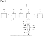
- the gas purification apparatus 1a includes a phase transitioning impurity removing unit 20 and a pressure swing adsorption apparatus 30 combined with a vacuum pump 40.
- the phase transitioning impurity removing unit 20 is provided in a subsequent stage after a cooling unit 10, and the pressure swing adsorption apparatus 30 is provided in a subsequent stage after the phase transitioning impurity removing unit 20.
- the "subsequent stage” means a subsequent stage along the supply flow of a raw material gas
- the "preceding stage” means a preceding stage along the supply flow of the raw material gas.
- the supply flow of the raw material gas G1 means the flow from the introduction of the raw material gas G1 into the gas purification apparatus 1a to the emission from the gas purification apparatus 1a as a purified gas G2, and in the present embodiment, it means the flow of the gas from the raw material gas generation facility 100 to the valuable material generation unit 110.
- a preceding stage treatment unit is preferably provided in a preceding stage before the phase transitioning impurity removing unit 20, and the raw material gas G1 may be appropriately pretreated at the preceding stage treatment unit before being supplied to the gas purification apparatus 1a.
- the preceding stage treatment unit removes various impurities, water, carbon dioxide, and the like included in the raw material gas G1.
- the preceding stage treatment unit may be omitted.
- the preceding stage treatment unit is not particularly limited, and examples thereof include a scrubber and a desulfurization apparatus.
- the scrubber contacts a cleaning liquid consisting of water or an oil with the raw material gas, and removes at least a part of a water-soluble impurity and an oil-soluble impurity from the raw material gas G1.
- the water-soluble impurity include an acid gas such as hydrogen sulfide, hydrogen chloride, and prussic acid, a basic gas such as ammonia, and an oxide such as NOx and SOx.
- examples of the oil-soluble impurity include BTEX, naphthalene, 1-naphthol, and 2-naphthol.
- the phase transitioning impurity removing unit 20 captures and removes a solid-phased phase transitioning impurity in the raw material gas G1 introduced into the phase transitioning impurity removing unit 20.
- the phase transitioning impurity removing unit 20 is not particularly limited as long as it can remove the solid-phased phase transitioning impurity, and a mist separator can also be adopted.
- the mist separator is not particularly limited, and examples thereof include a filter of a metal, a resin, a fiber, a ceramic, or the like, and a combination thereof may be used.
- the filter may have a single-layer mesh structure or a multi-layer mesh structure.
- the coarseness of the filter may be such that it can remove the solid-phased phase transitioning impurity, and by making the coarseness of the filter relatively coarse, clogging of the filter with the solid-phased phase transitioning impurity, condensed water, and the like can be suppressed and the frequency of filter replacement can be reduced.
- the "removing” means removing at least a part of a substance to be removed from a raw material gas to reduce the concentration of the substance to be removed in the gas, and is not limited to complete removal of the substance to be removed.
- PSA Pressure swing adsorption apparatus
- the pressure swing adsorption apparatus 30 is combined with the vacuum pump 40, and removes an impurity in the raw material gas G1 from which the solid-phased phase transitioning impurity has been removed at the phase transitioning impurity removing unit 20.
- the pressure swing adsorption apparatus 30 is not particularly limited as long as it can adsorb and remove a gas phase impurity such as carbon dioxide and BTEX, and examples thereof include a pressure vacuum swing adsorption (PVSA) apparatus into which a vacuum pump 40 is integrated.
- PVSA pressure vacuum swing adsorption
- the pressure swing adsorption apparatus 30 is an apparatus that has an adsorption tower filled with an adsorbent and repeats a purification step of adsorbing an impurity on the adsorbent with which the adsorption tower is filled by changing a pressure to remove the impurity and a regeneration step of desorbing the impurity adsorbed on the adsorbent.
- the adsorbent used in the pressure swing adsorption apparatus 30 may be composed of zeolite, silica gel, activated carbon, or the like, and zeolite or silica gel is preferable and zeolite is more preferable, from the viewpoint of efficiently removing a gas phase impurity such as carbon dioxide and BTEX.
- the vacuum pump 40 decompresses an adsorption unit provided with the adsorbent of the pressure swing adsorption apparatus 30 to desorb the gas phase impurity adsorbed on the adsorbent and promote emission.
- the gas phase impurity desorbed by the vacuum pump 40 is discharged through a discharge path 41 provided in the vacuum pump 40. That is, the vacuum pump 40 can prevent the gas phase impurity from accumulating on the surface of the adsorbent of the pressure swing adsorption apparatus 30 and can maintain the adsorbing ability of the adsorbent for a long period of time.
- the vacuum pump 40 can remove not only the gas phase impurity adsorbed on the adsorbent but also the phase transitioning impurity and water remaining in the adsorbent by decompressing the pressure swing adsorption apparatus 30 in the regeneration step.
- the phase transitioning impurity and water remaining in the adsorbent can be prevented from being contained in the raw material gas G1 by the vacuum pump 40 removing a part of the phase transitioning impurity and water remaining in the adsorbent in the regeneration step. That is, the vacuum pump 40 can prevent the phase transitioning impurity and water remaining in the adsorbent from being contained in the raw material gas G1 in the purification step and stably supply the purified gas G2.
- the pressure swing adsorption apparatus 30 will be described in more detail with reference to Fig. 2 .
- the number of adsorption towers in the pressure swing adsorption apparatus 30 is not limited to two, and may be three or more.
- the pressure swing adsorption apparatus 30 includes first and second adsorption towers 31 and 32, and an introduction path 21 for supplying the raw material gas G1 to the first and second adsorption towers 31 and 32 is connected.
- the introduction path 21 is branched into two branch paths 21a and 21b, and the branch paths 21a and 21b are connected to one ends 31a and 32b of the first and second adsorption towers 31 and 32, respectively. Further, valves 22a and 22b are attached to the branch paths 21a and 21b, respectively.
- a pressurizing device 23 is provided in the introduction path 21, and the raw material gas G1 pressurized by the pressurizing device 23 is supplied via the branch paths 21a and 21b to the first adsorption tower 31 or the second adsorption tower 32.
- the pressurizing device 23 may be any known one, and for example, a blower apparatus may be used.
- the raw material gas G1 may be pressurized to, for example, a gage pressure of 0 to 100 kPa, and preferably a gage pressure of 20 to 80 kPa by the pressurizing device 23.
- the raw material gas G1 is supplied to the first adsorption tower 31.
- the valve 22b is opened and the valve 22a is closed, the raw material gas G1 is supplied to the second adsorption tower 32.
- the purification step is carried out in each adsorption tower. Specifically, in one of the adsorption towers (either of the first and second adsorption towers 31 and 32) to which the raw material gas G1 is supplied, the raw material gas G1 is introduced into the inside of the tower from one end 31a or 32a thereof.
- the raw material gas G1 introduced into the inside of the tower passes through the inside of the first adsorption tower 31 or the second adsorption tower 32 and is emitted from the other end 31b or 32b thereof.
- the impurity included in the raw material gas G1 is adsorbed by the adsorbent. Therefore, the gas emitted from the other end 31b or 32b of the first adsorption tower 31 or the second adsorption tower 32 is supplied as the gas purified by the adsorption tower 21 (purified gas G2) via a supply path 33 (33a or 33b) to a valuable material generation reaction unit 110.
- the pressure swing adsorption apparatus 30 includes a vacuum pump 40, and the vacuum pump 40 is connected to the first adsorption tower 31 or the second adsorption tower 32 via a decompression path 42.
- the decompression path 42 is branched into two decompression paths 42a and 42b, and the decompression paths 42a and 42b are connected to one ends 31a and 32b of the first and second adsorption towers 31 and 32, respectively.
- the vacuum pump 40 can suck and decompress the inside of the first adsorption tower 31 or the second adsorption tower 32 to reduce the pressure via a decompression path 42a or a decompression path 42b.
- Valves 43a and 43b are provided in the decompression paths 42a and 42b, respectively.
- the regeneration step is carried out in the first adsorption tower 31.
- the regeneration step is carried out in the second adsorption tower 32.
- the above regeneration step may be allowed to proceed in parallel with the purification step. Specifically, while passing the waste-derived raw material gas G1 through one of the adsorption towers, the other adsorption tower is sucked by the vacuum pump 40 to create a decompressed state, and then after the vacuuming is completed, purging with a purge gas such as nitrogen gas may be carried out to carry out the regeneration step in the other adsorption tower.
- the purge gas used in the regeneration step is introduced into the inside of the first and second adsorption towers 31 and 32 from purge paths (not shown) provided at the other ends 31b and 32b thereof, respectively.
- the purge gas introduced into the inside of the towers passes through the inside of the first and second adsorption towers 31 and 32 and is exhausted as an exhaust gas from one ends 31a and 32b of the first and second adsorption towers 31 and 32, respectively, via the decompression path 42.
- each of the first and second adsorption towers 31 and 32 opening and closing of each valve may be repeated to alternately repeat the above purification step and regeneration step.
- a plurality of adsorption towers are provided as described above, and the raw material gas G1 is sequentially purified by the plurality of adsorption towers to continuously purify the raw material gas by the adsorption towers.
- the vacuum pump 40 not only removes the gas phase impurity adsorbed on the adsorbent for regeneration, but also removes the phase transitioning impurity and water remaining in the adsorbent, by decompressing the first and second adsorption towers 31 and 32.
- the phase transitioning impurity and water remaining in the adsorbent removed by the vacuum pump 40 are discharged through a discharge path 41.
- the phase transitioning impurity and water remaining in the adsorbent can be prevented from being contained in the raw material gas G1 by the vacuum pump 40 removing a part of the phase transitioning impurity and water remaining in the adsorbent in the regeneration step. That is, the vacuum pump 40 can prevent the phase transitioning impurity and water remaining in the adsorbent from being contained in the raw material gas G1 in the purification step and stably supply the purified gas G2.
- the purification step carried out in each of the adsorption towers 31 and 32 of the pressure swing adsorption apparatus 30 may be continuously carried out for a predetermined time, for example, 0.1 to 10 minutes and preferably 0.5 to 5 minutes.
- each of the first and second adsorption towers 31 and 32 is decompressed by the vacuum pump 40 to, for example, a gage pressure of 0 to - 101.3 kPa and preferably a gage pressure of -60 to -98 kPa in the regeneration step.
- the vacuum pump 40 in each adsorption tower may be carried out for about the same time as the that of the purification step or for a shorter time from the viewpoint of the power consumed by the vacuum pump, for example, for a shorter time by 0 to 70% and preferably 5 to 50% than the time of the purification step.
- the gas from which the impurity has been removed by the pressure swing adsorption apparatus 30 is appropriately treated by a subsequent stage treatment unit (not shown), if necessary, and then supplied to the valuable material generation unit 110 as the purified gas G2.
- the subsequent stage treatment unit is not particularly limited, and examples thereof include a temperature swing adsorption apparatus, a metal catalyst such as copper and palladium, and various cleaning apparatuses such as various filters. Of course, the subsequent stage treatment unit may be omitted.
- the valuable material generation unit 110 has a catalyst such as an organic catalyst or a metal catalyst.
- the purified gas G2 comes into contact with a catalyst such as an organic catalyst or a metal catalyst and is converted into a valuable material.
- the valuable material is not particularly limited as long as it is an organic compound that can be converted from a synthetic gas, and ethanol is preferable. Ethanol can be easily synthesized from hydrogen and carbon monoxide included in a synthetic gas.
- an organic catalyst is preferable.
- a gas-utilizing microorganism is preferably used as the organic catalyst.
- a synthetic gas is supplied to the inside of a fermenter filled with the gas-utilizing microorganism, and the synthetic gas is microbially fermented in the microbial fermenter to produce ethanol.
- the gas-utilizing microorganism for example, anaerobic bacteria disclosed in PTL 2 mentioned above, WO 2011/087380 A , US 2013/0065282 A , and the like can be used.
- a purification unit including a distillation tower is provided in the subsequent stage of the valuable material generation reaction unit 110, and the purification unit extracts a valuable material such as ethanol.
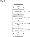
- the method for producing a purified gas according to the first embodiment includes a solid-phased impurity removing step S11 and an impurity removing step S12.
- the method for producing a purified gas according to the first embodiment will be described with reference to Fig. 1 and Fig. 3 .
- the filter provided in the phase transitioning impurity removing unit 20
- the solid-phased phase transitioning impurity is removed by the filter.
- the filter provided in the phase transitioning impurity removing unit 20 can remove a part of a solid-liquid phase impurity such as soot and tar in the raw material gas G1.
- the raw material gas G1 after the solid-phased impurity removing step S11 is passed through the pressure swing adsorption apparatus 30 combined with the vacuum pump 40 to remove an impurity in the raw material gas G1.
- a gas phase impurity such as carbon dioxide and BTEX in the raw material gas G1 is adsorbed by the adsorption unit and removed.
- the vacuum pump 40 decompresses the adsorption unit provided with the adsorbent of the pressure swing adsorption apparatus 30 to desorb the gas phase impurity adsorbed on the adsorbent. Then, the vacuum pump 40 discharges an exhaust gas including the gas phase impurity through the discharge path 41.
- the vacuum pump 40 can remove not only the gas phase impurity adsorbed on the adsorbent but also the phase transitioning impurity and water remaining in the adsorbent by decompressing the pressure swing adsorption apparatus 30. Then, the vacuum pump 40 discharges an exhaust gas including the phase transitioning impurity and water through the discharge path 41.
- the purified gas G2 generated through the impurity removing step S12 is introduced into the valuable material generation reaction unit 110, and the valuable material generation reaction unit 110 generates a valuable material such as ethanol from the purified gas G2.
- the vacuum pump can prevent an impurity from accumulating on the surface of an adsorbent of the pressure swing adsorption apparatus and can maintain the adsorbing ability of the adsorbent of the pressure swing adsorption apparatus for a long period of time.
- the vacuum pump can emit a part of the phase transitioning impurity in the raw material gas and thus, together with the phase transitioning impurity removing unit, can remove the phase transitioning impurity contained in the raw material gas, and clogging of the filter installed in the mainstream with the phase transitioning impurity can be suppressed. Because of this, maintenance such as filter replacement can be alleviated, and operating costs can be reduced.
- the vacuum pump can emit a part of the water in the raw material gas and thus can play a part of the role of emitting the water in the raw material gas, and operating costs such as the amount of electricity used can be reduced as compared with emitting the water in the raw material gas only by cooling and condensing the raw material gas using the cooling unit.
- an impurity in a raw material gas which is a waste-derived gas
- a gas-utilizing microorganism can be stably cultured.
- a gas purification apparatus 1b in the second embodiment further includes a cooling unit 10 on the upstream side of a phase transitioning impurity removing unit 20.
- the cooling unit 10 cools the raw material gas G1 introduced therein so that a phase transitioning impurity is changed into solid-phase.
- the cooling temperature is determined according to the amount of the phase transitioning impurity removed by the cooling unit 10.
- the temperature of the raw material gas G1 at the time of generation at a raw material gas generation facility 100 or at the time of delivery from the raw material gas generation facility 100 is higher than normal temperature, for example, about 30°C to several hundred degrees C.
- the phase transition temperature refers to the temperature at which a phase transitioning impurity phase-transitions, and specifically refers to the temperature at which a phase transitioning impurity sublimates.
- the cooling target temperature of the cooling unit 10 is set within a range in which a phase transition of the phase transitioning impurity contained in the raw material gas G1 (for example, sublimation and solidification of naphthalene) can sufficiently occur.
- the cooling target temperature of the cooling unit 10 may encompass the phase transition temperature of the phase transitioning impurity, and is preferably 5°C or more and 40°C or less, more preferably 10°C or more and 40°C or less, further preferably 15°C or more and 35°C or less, and more further preferably 20°C or more and 30°C or less.
- the cooling temperature of the cooling unit 10 is equal to or more than the above lower limit, it is possible to prevent clogging due to freezing of a tube, a filter, and the like in the mainstream.
- the cooling temperature is equal to or more than the above lower limit, the energy for lowering the temperature can be suppressed and operating costs can be reduced.
- the configuration of the present invention is adopted, no problem occurs because the pressure swing adsorption apparatus 30 can remove the phase transitioning impurity even if the cooling unit 10 is operated under a relatively high temperature condition of, for example, 20°C or more; and the energy required for operation of the vacuum pump 40 is smaller than the energy required for cooling, and thus this case is energetically advantageous.
- the cooling temperature is equal to or more than the above lower limit, it is also possible to prevent the phase transitioning impurity from being too solid-phased and causing clogging in the filter or the like.
- the temperature of the raw material gas G1 between the cooling unit 10 and the pressure swing adsorption apparatus 30 is equal to or more than the above lower limit, and thus a component of the raw material gas G1 does not freeze to cause clogging in the filter or the like.
- by appropriately adjusting the temperature it is also possible to prevent the phase transitioning impurity in the raw material gas G1 from being too solid-phased and causing clogging in the filter or the like.
- cooling unit 10 examples include a heat exchanger (chiller) and a scrubber.
- the heat exchanger (chiller) as the cooling unit 10 is preferably a shell and tube type heat exchanger composed of a plurality of cooling tubes.
- the cooling tubes are preferably straight tubes from the viewpoint of ease of cleaning, and the cooling tubes are preferably arranged in parallel with each other with the tube axes facing up and down.
- a refrigerant such as ethylene glycol flows outside the cooling tubes, and cools the raw material gas G1 introduced into the cooling unit 10 flowing inside the cooling tubes.
- the cooling unit 10 includes a drain path 11, and emits the phase transitioning impurity and water in the raw material gas G1 condensed by cooling from the drain path 11.
- the scrubber as the cooling unit 10 is preferably a water scrubber.
- the cooling unit 10 When the cooling unit 10 is a water scrubber, it includes a circulating water supply path (not shown) for supplying circulating water inside the water scrubber.
- the water scrubber preferably has a filler inside for increasing the gas-liquid contact efficiency between the raw material gas G1 and the circulating water.
- the water scrubber has a heat exchanger outside, and the circulating water inside the water scrubber is kept at a constant temperature by cooling the heat exchanger.
- the raw material gas G1 introduced into the cooling unit 10 comes into gas-liquid contact with the circulating water inside the water scrubber and is cooled.
- the cooling unit 10 includes a drain path 11, and emits the phase transitioning impurity and water in the raw material gas G1 condensed by cooling together with the circulating water from the drain path 11.
- the method for producing a purified gas according to the second embodiment further includes a cooling step S10.
- the raw material gas G1 is cooled to the phase transition temperature of the phase transitioning impurity.
- the raw material gas G1 generated by the raw material gas generation facility 11 is cooled by the cooling unit 10.
- the raw material gas G1 generated by the raw material gas generation facility 100 is cooled to a temperature equal to or less than the phase transition temperature of the phase transitioning impurity by the cooling unit 10 to change the phase transitioning impurity contained in the raw material gas G1 into solid-phase.
- the same effects as described in the gas purification apparatus and the method for producing a purified gas according to the first embodiment can be exhibited.
- a raw material gas can be cooled to the transition temperature or less by a cooling unit to change a phase transitioning impurity contained in the raw material gas into solid-phase, and the phase transitioning impurity can be efficiently removed by a phase transitioning impurity removing unit. Because of this, a filter installed in the mainstream can be prevented from being clogged with the phase transitioning impurity, and maintenance such as filter replacement can be alleviated and operating costs can be reduced.
- a gas purification apparatus 1c in the third embodiment further includes a solid-liquid impurity removing unit 50 in a discharge path 41 on the downstream side of a vacuum pump 40.
- the solid-liquid impurity removing unit 50 removes a solid phase impurity and a liquid phase impurity in an exhaust gas discharged from the vacuum pump 40. Specifically, the solid-liquid impurity removing unit 50 removes an impurity that is gas phase after being discharged from the vacuum pump 40 but is solid-phased or liquid-phased when the impurity is separated from the vacuum pump 40 and thereby put under normal temperature and normal pressure. Therefore, the solid-liquid impurity removing unit 50 is preferably provided in the discharge path 41 on the downstream side of the vacuum pump 40, after a place where an impurity to be solid-phased or liquid-phased occurs.
- Examples of the solid phase impurity removed by the solid-liquid impurity removing unit 50 include a phase transitioning impurity and dust solid-phased by a decrease in temperature.
- Examples of the liquid phase impurity removed by the solid-liquid impurity removing unit 50 include a liquid-phased water droplet.
- the solid-liquid impurity removing unit 50 is not particularly limited as long as it can remove a solid phase impurity and a liquid phase impurity, and examples thereof include a mist separator.
- the mist separator is not particularly limited, and examples thereof include a filter of a metal, a resin, a fiber, a ceramic, or the like, and a combination thereof may be used.
- the filter may have a single-layer mesh structure or a multi-layer mesh structure.
- the coarseness of the filter may be such that it can remove a solid phase impurity and a liquid phase impurity, and by making the coarseness of the filter relatively coarse, clogging of the filter with a solid phase impurity, a liquid phase impurity, condensed water, and the like can be suppressed and the frequency of filter replacement can be reduced.
- the method for producing a purified gas according to the third embodiment further includes a solid-liquid impurity removing step S13.
- an exhaust gas discharged from the vacuum pump 40 is passed through the solid-liquid impurity removing unit 50 to remove the solid phase impurity and the liquid phase impurity in the exhaust gas.
- the solid-liquid impurity removing unit 50 by passing the raw material gas G1 after the impurity removing step S12 through the solid-liquid impurity removing unit 50, an impurity in the raw material gas G1 that has not been able to be completely removed in the solid-phased impurity removing step S11 and the impurity removing step S12 is removed.
- clogging in the discharge paths 41 and 51 after the discharge from the vacuum pump 40 can be suppressed by the solid-liquid impurity removing unit 50 removing an impurity that is gas phase after being discharged from the vacuum pump 40, but is solid-phased or liquid-phased when the impurity is separated from the vacuum pump 40 and thereby put under normal temperature and normal pressure.
- the same effects as described in the gas purification apparatuses and the methods for producing a purified gas according to the first and second embodiments can be exhibited.
- clogging in a discharge path of a vacuum pump can also be suppressed by a solid-liquid impurity removing unit removing a solid phase impurity and a liquid phase impurity in a raw material gas.
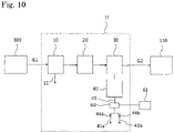
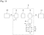
- a vacuum pump 40 of each of gas purification apparatuses 1d and 1e according to the fourth embodiment includes a plurality of discharge paths 41a and 41b that can each be selected as a flow path of an exhaust gas to be discharged.
- the vacuum pump 40 includes the same number of discharge ports as that of the plurality of discharge paths 41a and 41b.
- the flow path of the exhaust gas to be discharged from the vacuum pump 40 can be selected by valves 44a and 44b provided in the discharge paths 41a and 41b, respectively.
- the vacuum pump 40 in the gas purification apparatus 1d when the valve 44a is opened and the valve 44b is closed, the exhaust gas is discharged through the discharge path 41a.
- the valve 44b is opened and the valve 44a is closed, the exhaust gas is discharged through the discharge path 41b.
- the vacuum pump 40 includes one discharge port and includes a plurality of discharge paths 41a and 41b branching from the discharge path 41 connected to the discharge port.
- the flow path of the exhaust gas to be discharged from the vacuum pump 40 can be selected by valves 44a and 44b on the upstream side and valves 45a and 45b on the downstream side provided in the discharge paths 41a and 41b, respectively.
- the vacuum pump 40 in the gas purification apparatus 1e when the valves 44a and 45a are opened and the valves 44b and 45b are closed, the exhaust gas is discharged through the discharge path 41a.
- the valves 44b and 45b are opened and the valves 44a and 45b are closed, the exhaust gas is discharged through the discharge path 41b.
- the same effects as described in the gas purification apparatuses and the methods for producing a purified gas according to the first and second embodiments can be exhibited.
- the gas purification apparatus and the method for producing a purified gas according to the fourth embodiment of the present invention by providing a plurality of discharge paths that can each be selected as a flow path of an exhaust gas to be discharged from a vacuum pump, even if any of the discharge paths is clogged, the operation can be continued by another discharge path.
- a discharge path that is not used for operation can be cleaned, and clogging can be prevented.
- gas purification can be continuously carried out and the risk of stopping the supply of the raw material gas to a fermenter can be reduced or eliminated. Because of this, the purified raw material gas continuously enters the fermenter, which makes it possible to maintain the productivity of an organic substance and the activity of a catalyst. If the catalyst is a microorganism, the activity may decrease because of a sudden change in the raw material composition, or the microorganism may die at worst when the supply of the raw material gas is stopped.
- the thermal conductivity to the outside air is lowered and the tube is unlikely to be cooled, and thus the amount of precipitation can be reduced.
- a gas purification apparatus 1f includes a pressure gage 60 measuring the pressure of an exhaust gas to be discharged on the discharge side of a vacuum pump 40.
- the pressure gage 60 measures the pressure of the exhaust gas flowing on the discharge side (for example, through a discharge path 41) of the vacuum pump 40.
- the pressure gage 60 transmits measured pressure data to a control unit 61.
- the control unit 61 controls selection of a flow path of the exhaust gas to be discharged from the vacuum pump 40 based on the pressure data received.
- the control by the control unit 61 is, for example, a control in which when the pressure data received is higher than a predetermined value, it is determined that the currently selected flow path is clogged and another flow path is selected.
- the place at which the pressure gage 60 is installed is not limited to the discharge path 41 immediately after the discharge side of the vacuum pump 40, and the pressure gage 60 may be installed in a plurality of discharge paths 41a and 41b.
- the same effects as described in the gas purification apparatuses and the methods for producing a purified gas according to the first and second embodiments can be exhibited.
- the gas purification apparatus and the method for producing a purified gas according to the fifth embodiment of the present invention, by providing a pressure gage measuring the pressure of an exhaust gas on the discharge side of a vacuum pump, the pressure in a discharge path can be known, and an abnormality such as pressure rise due to clogging of a discharge path or the like can be immediately detected and dealt with.
- the gas purification apparatus 1c according to the third embodiment and the gas purification apparatus 1e according to the fourth embodiment may be combined.
- a solid-liquid impurity removing unit 50 may be provided immediately after the downstream side of a vacuum pump 40, before branching into a plurality of discharge paths 41a and 41b.
- a solid-liquid impurity removing unit 50 may be provided in each of a plurality of discharge paths 41a and 41b.
- a solid-liquid impurity removing unit 50 may be provided after a plurality of discharge paths 41a and 41b have merged.
Landscapes
- Chemical & Material Sciences (AREA)
- Engineering & Computer Science (AREA)
- Combustion & Propulsion (AREA)
- General Chemical & Material Sciences (AREA)
- Oil, Petroleum & Natural Gas (AREA)
- Chemical Kinetics & Catalysis (AREA)
- Organic Chemistry (AREA)
- Analytical Chemistry (AREA)
- Separation Of Gases By Adsorption (AREA)
- Industrial Gases (AREA)
Applications Claiming Priority (2)
| Application Number | Priority Date | Filing Date | Title |
|---|---|---|---|
| JP2019172541 | 2019-09-24 | ||
| PCT/JP2020/035837 WO2021060289A1 (ja) | 2019-09-24 | 2020-09-23 | 精製ガスの製造方法、有価物の製造方法、ガス精製装置及び有価物製造装置 |
Publications (2)
| Publication Number | Publication Date |
|---|---|
| EP4036192A1 true EP4036192A1 (de) | 2022-08-03 |
| EP4036192A4 EP4036192A4 (de) | 2023-10-04 |
Family
ID=75166151
Family Applications (1)
| Application Number | Title | Priority Date | Filing Date |
|---|---|---|---|
| EP20869003.2A Pending EP4036192A4 (de) | 2019-09-24 | 2020-09-23 | Verfahren zur herstellung von gereinigtem gas, verfahren zur herstellung von wertstoffen, gasreinigungsvorrichtung und vorrichtung zur herstellung von wertstoffen |
Country Status (5)
| Country | Link |
|---|---|
| US (1) | US12415157B2 (de) |
| EP (1) | EP4036192A4 (de) |
| JP (1) | JP7547355B2 (de) |
| CN (1) | CN114401781A (de) |
| WO (1) | WO2021060289A1 (de) |
Families Citing this family (3)
| Publication number | Priority date | Publication date | Assignee | Title |
|---|---|---|---|---|
| JP7679707B2 (ja) * | 2021-06-22 | 2025-05-20 | 富士電機株式会社 | 燃料電池発電装置 |
| EP4685222A1 (de) * | 2023-03-23 | 2026-01-28 | Sekisui Chemical Co., Ltd. | System zur herstellung einer organischen substanz, vorrichtung zur herstellung einer organischen substanz und verfahren zur herstellung einer organischen substanz |
| CN118931706B (zh) * | 2024-07-31 | 2026-01-16 | 贵州金泽新能源科技有限公司 | 一种发酵供气系统与发酵供气系统的供气方法 |
Family Cites Families (12)
| Publication number | Priority date | Publication date | Assignee | Title |
|---|---|---|---|---|
| JPH0683772B2 (ja) * | 1986-10-23 | 1994-10-26 | 株式会社神戸製鋼所 | 圧力スイング吸着方法 |
| US5243519A (en) | 1992-02-18 | 1993-09-07 | International Business Machines Corporation | Method and system for language translation within an interactive software application |
| JP4594821B2 (ja) | 2005-08-05 | 2010-12-08 | 新日鉄エンジニアリング株式会社 | ガス化ガスの精製方法 |
| JP2008222882A (ja) | 2007-03-13 | 2008-09-25 | Nippon Steel Engineering Co Ltd | ガス化ガスの浄化方法及び浄化装置 |
| EA021007B1 (ru) | 2009-04-29 | 2015-03-31 | Ланзатек Нью Зиленд Лимитед | Способ ферментативного превращения углеродсодержащего сырья |
| ES2690151T3 (es) | 2010-01-14 | 2018-11-19 | Lanzatech New Zealand Limited | Fermentación de CO2 usando un potencial eléctrico |
| EP2753700B1 (de) | 2011-09-08 | 2020-02-19 | Lanzatech New Zealand Limited | Fermentierungsverfahren |
| JP6134347B2 (ja) | 2015-03-30 | 2017-05-24 | 積水化学工業株式会社 | 有価物生成方法及び装置 |
| CN105749699B (zh) * | 2016-03-31 | 2020-04-21 | 四川天采科技有限责任公司 | 一种全温程变压吸附气体分离提纯与净化的方法 |
| WO2017212605A1 (ja) | 2016-06-09 | 2017-12-14 | 積水化学工業株式会社 | 廃棄物から有機物質を製造する装置及び廃棄物から有機物質を製造する方法 |
| JP6696876B2 (ja) * | 2016-10-06 | 2020-05-20 | 積水化学工業株式会社 | 合成ガスの浄化処理方法及び装置 |
| CN107096370A (zh) | 2017-06-30 | 2017-08-29 | 大唐环境产业集团股份有限公司 | 一种制浆排放装置 |
-
2020
- 2020-09-23 JP JP2021548939A patent/JP7547355B2/ja active Active
- 2020-09-23 WO PCT/JP2020/035837 patent/WO2021060289A1/ja not_active Ceased
- 2020-09-23 EP EP20869003.2A patent/EP4036192A4/de active Pending
- 2020-09-23 US US17/761,409 patent/US12415157B2/en active Active
- 2020-09-23 CN CN202080065349.7A patent/CN114401781A/zh active Pending
Also Published As
| Publication number | Publication date |
|---|---|
| US20220347624A1 (en) | 2022-11-03 |
| JP7547355B2 (ja) | 2024-09-09 |
| EP4036192A4 (de) | 2023-10-04 |
| WO2021060289A1 (ja) | 2021-04-01 |
| JPWO2021060289A1 (de) | 2021-04-01 |
| US12415157B2 (en) | 2025-09-16 |
| CN114401781A (zh) | 2022-04-26 |
Similar Documents
| Publication | Publication Date | Title |
|---|---|---|
| KR101886900B1 (ko) | 바이오가스로부터 메탄을 분리 및 정제시키기 위한 방법 및 시스템 | |
| CN105749699B (zh) | 一种全温程变压吸附气体分离提纯与净化的方法 | |
| KR101388266B1 (ko) | 고로가스의 분리방법 및 장치 | |
| US12415157B2 (en) | Method for producing purified gas, method for producing valuable material, gas purification device, and device for producing valuable material | |
| US20090214902A1 (en) | Adsorptive Bulk Separation for Upgrading Gas Streams | |
| US8361198B2 (en) | Process and device for the separation of foreign gases from a reducing useful gas by steam-driven pressure swing adsorption | |
| JP6696876B2 (ja) | 合成ガスの浄化処理方法及び装置 | |
| JP2021049482A (ja) | 精製ガスの製造方法及びガス精製装置 | |
| JP2026009353A (ja) | 有機物質の製造方法、及び有機物質製造装置 | |
| JP2026015334A (ja) | 熱分解ガス精製冷却装置及び熱分解ガス精製冷却方法、並びに、有機物質製造装置及び有機物質の製造方法 | |
| JP6134347B2 (ja) | 有価物生成方法及び装置 | |
| CN109069980B (zh) | 变压吸附式气体分离方法及气体分离装置 | |
| US12618032B2 (en) | Method for producing organic substance and device for producing organic substance | |
| US12378487B2 (en) | Method for producing organic substance and apparatus for producing organic substance | |
| JP2003054928A (ja) | 二酸化炭素分離方法及びその装置並びにシステム | |
| JP6721697B2 (ja) | 有価物生成方法及び装置 | |
| WO2024257873A1 (ja) | 有機物質製造装置、及び有機物質製造方法 | |
| JP2025115974A (ja) | 有価物の製造システム、有価物の製造装置及び有価物の製造方法 | |
| CN121060226A (zh) | 基于膜分离与多级吸附的石灰窑尾气二氧化碳回收提纯系统及方法 | |
| KR20100109108A (ko) | 합성가스에서의 이산화탄소 분리장치 | |
| HK1148978A (en) | Method and device for the separation of foreign gases from a reducing useful gas by pressure swing adsorption |
Legal Events
| Date | Code | Title | Description |
|---|---|---|---|
| STAA | Information on the status of an ep patent application or granted ep patent |
Free format text: STATUS: THE INTERNATIONAL PUBLICATION HAS BEEN MADE |
|
| PUAI | Public reference made under article 153(3) epc to a published international application that has entered the european phase |
Free format text: ORIGINAL CODE: 0009012 |
|
| STAA | Information on the status of an ep patent application or granted ep patent |
Free format text: STATUS: REQUEST FOR EXAMINATION WAS MADE |
|
| 17P | Request for examination filed |
Effective date: 20220316 |
|
| AK | Designated contracting states |
Kind code of ref document: A1 Designated state(s): AL AT BE BG CH CY CZ DE DK EE ES FI FR GB GR HR HU IE IS IT LI LT LU LV MC MK MT NL NO PL PT RO RS SE SI SK SM TR |
|
| DAV | Request for validation of the european patent (deleted) | ||
| DAX | Request for extension of the european patent (deleted) | ||
| REG | Reference to a national code |
Ref country code: DE Ref legal event code: R079 Free format text: PREVIOUS MAIN CLASS: C10K0001040000 Ipc: C10K0001020000 |
|
| A4 | Supplementary search report drawn up and despatched |
Effective date: 20230906 |
|
| RIC1 | Information provided on ipc code assigned before grant |
Ipc: C12P 7/06 20060101ALI20230831BHEP Ipc: C07C 29/151 20060101ALI20230831BHEP Ipc: B01D 53/047 20060101ALI20230831BHEP Ipc: C10K 1/32 20060101ALI20230831BHEP Ipc: C10K 1/04 20060101ALI20230831BHEP Ipc: C10K 1/02 20060101AFI20230831BHEP |