EP4036207A1 - Verwendung einer trennvorrichtung in seed train - Google Patents
Verwendung einer trennvorrichtung in seed train Download PDFInfo
- Publication number
- EP4036207A1 EP4036207A1 EP21187619.8A EP21187619A EP4036207A1 EP 4036207 A1 EP4036207 A1 EP 4036207A1 EP 21187619 A EP21187619 A EP 21187619A EP 4036207 A1 EP4036207 A1 EP 4036207A1
- Authority
- EP
- European Patent Office
- Prior art keywords
- inflow
- inlet opening
- separating apparatus
- sedimentation
- settler
- Prior art date
- Legal status (The legal status is an assumption and is not a legal conclusion. Google has not performed a legal analysis and makes no representation as to the accuracy of the status listed.)
- Granted
Links
Images













Classifications
-
- B—PERFORMING OPERATIONS; TRANSPORTING
- B01—PHYSICAL OR CHEMICAL PROCESSES OR APPARATUS IN GENERAL
- B01D—SEPARATION
- B01D21/00—Separation of suspended solid particles from liquids by sedimentation
- B01D21/0039—Settling tanks provided with contact surfaces, e.g. baffles, particles
- B01D21/0042—Baffles or guide plates
-
- B—PERFORMING OPERATIONS; TRANSPORTING
- B01—PHYSICAL OR CHEMICAL PROCESSES OR APPARATUS IN GENERAL
- B01D—SEPARATION
- B01D21/00—Separation of suspended solid particles from liquids by sedimentation
- B01D21/0039—Settling tanks provided with contact surfaces, e.g. baffles, particles
- B01D21/0045—Plurality of essentially parallel plates
-
- B—PERFORMING OPERATIONS; TRANSPORTING
- B01—PHYSICAL OR CHEMICAL PROCESSES OR APPARATUS IN GENERAL
- B01D—SEPARATION
- B01D21/00—Separation of suspended solid particles from liquids by sedimentation
- B01D21/0039—Settling tanks provided with contact surfaces, e.g. baffles, particles
- B01D21/0057—Settling tanks provided with contact surfaces, e.g. baffles, particles with counter-current flow direction of liquid and solid particles
-
- C—CHEMISTRY; METALLURGY
- C12—BIOCHEMISTRY; BEER; SPIRITS; WINE; VINEGAR; MICROBIOLOGY; ENZYMOLOGY; MUTATION OR GENETIC ENGINEERING
- C12M—APPARATUS FOR ENZYMOLOGY OR MICROBIOLOGY; APPARATUS FOR CULTURING MICROORGANISMS FOR PRODUCING BIOMASS, FOR GROWING CELLS OR FOR OBTAINING FERMENTATION OR METABOLIC PRODUCTS, i.e. BIOREACTORS OR FERMENTERS
- C12M27/00—Means for mixing, agitating or circulating fluids in the vessel
- C12M27/02—Stirrer or mobile mixing elements
-
- C—CHEMISTRY; METALLURGY
- C12—BIOCHEMISTRY; BEER; SPIRITS; WINE; VINEGAR; MICROBIOLOGY; ENZYMOLOGY; MUTATION OR GENETIC ENGINEERING
- C12M—APPARATUS FOR ENZYMOLOGY OR MICROBIOLOGY; APPARATUS FOR CULTURING MICROORGANISMS FOR PRODUCING BIOMASS, FOR GROWING CELLS OR FOR OBTAINING FERMENTATION OR METABOLIC PRODUCTS, i.e. BIOREACTORS OR FERMENTERS
- C12M27/00—Means for mixing, agitating or circulating fluids in the vessel
- C12M27/18—Flow directing inserts
- C12M27/20—Baffles; Ribs; Ribbons; Auger vanes
-
- C—CHEMISTRY; METALLURGY
- C12—BIOCHEMISTRY; BEER; SPIRITS; WINE; VINEGAR; MICROBIOLOGY; ENZYMOLOGY; MUTATION OR GENETIC ENGINEERING
- C12M—APPARATUS FOR ENZYMOLOGY OR MICROBIOLOGY; APPARATUS FOR CULTURING MICROORGANISMS FOR PRODUCING BIOMASS, FOR GROWING CELLS OR FOR OBTAINING FERMENTATION OR METABOLIC PRODUCTS, i.e. BIOREACTORS OR FERMENTERS
- C12M33/00—Means for introduction, transport, positioning, extraction, harvesting, peeling or sampling of biological material in or from the apparatus
- C12M33/22—Settling tanks; Sedimentation by gravity
-
- C—CHEMISTRY; METALLURGY
- C12—BIOCHEMISTRY; BEER; SPIRITS; WINE; VINEGAR; MICROBIOLOGY; ENZYMOLOGY; MUTATION OR GENETIC ENGINEERING
- C12M—APPARATUS FOR ENZYMOLOGY OR MICROBIOLOGY; APPARATUS FOR CULTURING MICROORGANISMS FOR PRODUCING BIOMASS, FOR GROWING CELLS OR FOR OBTAINING FERMENTATION OR METABOLIC PRODUCTS, i.e. BIOREACTORS OR FERMENTERS
- C12M47/00—Means for after-treatment of the produced biomass or of the fermentation or metabolic products, e.g. storage of biomass
- C12M47/02—Separating microorganisms from the culture medium; Concentration of biomass
-
- B—PERFORMING OPERATIONS; TRANSPORTING
- B01—PHYSICAL OR CHEMICAL PROCESSES OR APPARATUS IN GENERAL
- B01D—SEPARATION
- B01D2221/00—Applications of separation devices
- B01D2221/06—Separation devices for industrial food processing or agriculture
Definitions
- sedimentation separators are known in order to achieve high viable cell concentrations in suspensions and to remove sensitive products, like highly glycosylated polypeptides and proteins.
- sedimentation settlers are used that are inclined from the vertical and comprise a plurality of long and narrow tubes or channels. Larger cells are removed from the suspension by settling onto the upward-facing surfaces of the settler, where they form thin sediment layers that slide down and are collected at the bottom of a vessel located underneath the sedimentation settler.
- An example of such sedimentation separator is shown in WO 03/020919 .
- DE-A-36 19 926 describes an apparatus for treating a liquid containing a depositing contamination of solid particles, which apparatus includes at least one chamber through which the liquid can flow and which has liquid feed and outlet connections and which apparatus is furnished with guide surfaces to guide the liquid into the separation chamber.
- Fig. 2 of DE-A-36 19 926 shows a stationary separator being primarily designed to remove solid particles from water and oil.
- the separator includes a housing which houses a deposition chamber.
- the contaminated water is passed through the contaminated water supply and comes in a pre-separation chamber. Throughout the deposition, a low flow rate is adjusted so that the separation of the components occurs by the force of gravity.
- a portion of the oil collects in the pre-separation chamber already above and can be discharged through the oil drain.
- a portion of the solids sink to the bottom of the pre-separation chamber and comes down into the deposition chamber.
- the pre-treated water then flows with low flow rate through a package of dividers upwards.
- EP-A-0 003 146 discloses a device for separating water and water-insoluble, light substances contained therein, for example, oil.
- the device comprises a reservoir for receiving a mixture of water and substances and a plurality of sequential, parallel, sloping separation channels arranged in the reservoir and bounded by channel walls, an inlet chamber, a mixture inlet opening out in the inlet chamber and distributing the mixture at right angles to the plane of the drawing, a feeding chamber communicating with the inlet chamber, a substance outlet, a layer-limit sensor , an overflow with an overflow rim, a water outlet communicating with the overflow and a screen separating the overflow from a collecting space for light substances.
- the assembly of separation channels is arranged between the feeding chamber and an outlet chamber of the reservoir.
- the mixture flows through a dosing member, in which flocculation promoting chemicals are added to the mixture and through a mixer towards the mixture inlet.
- the desired flocculation takes place in the feeding chamber.
- the invention provides a separating apparatus comprising a sedimentation settler and a collection vessel.
- the collection vessel is disposed underneath the sedimentation settler and is also in fluid communication with the sedimentation settler.
- the collection vessel forms a receiving chamber that has an outlet at or adjacent to the chamber bottom and has an inlet opening.
- the collection vessel has one inlet opening.
- the collection vessel is arranged such that the flow direction of the fluid in the area underneath the sedimentation settler is substantially in line with the direction of the channels of the sedimentation settler.
- the inflow inlet opening is preferably located at the same vertical height level of the separating apparatus as the lower edge of the sedimentation settler or below.
- the inflow inlet opening is preferably located at a vertical height level below the lower edge of the sedimentation settler.
- the inflow inlet opening is preferably located at the same vertical height level of the separating apparatus as the lower edge of the sedimentation settler.
- the invention provides a separating apparatus comprising a sedimentation settler and a collection vessel.
- the collection vessel is disposed underneath the sedimentation settler and is also in fluid communication with the sedimentation settler.
- the collection vessel forms a receiving chamber that has an outlet at or adjacent to the chamber bottom and has an inlet opening.
- the collection vessel has one inlet opening.
- the inlet opening may be located at the upstanding side wall of the collection vessel.
- the collection vessel comprises an inflow deflection element.
- the inlet is below the lower edge of the sedimentation settler.
- the invention also encompasses that the plates of the sedimentation settler do not extend into the collection vessel.
- a single inflow deflection element is provided.
- the deflection element is adapted such that the retention or dwell time of a particle and/or the hydraulic dwell time, for example of a cell suspension, in the collection vessel is reduced, for example compared to a separating apparatus having a collection vessel without a deflection element.
- the size of the collection vessel and the deflection element are adapted to each other such that the retention or dwell time of a fluid in the collection vessel is reduced compared to a separating apparatus having a collection vessel without a deflection element.
- the deflection element impedes the liquid flow to flow along its natural path guided by gravity and urges the stream of liquid to change its direction downwardly.
- the wall of the receiving chamber may be curved such that the horizontal cross-sectional area decreases towards the bottom thereof.
- the receiving chamber has the shape of an inverse cone or truncated cone, or is cup-shaped or bowl-shaped, i.e. having a curved inner wall allowing to optimize the volume.
- the arrangement and shape of the deflection element and the curvature of the receiving chamber may be adapted to each other such that the initially downwardly deflected inflow is further guided up towards the sedimentation settler.
- the inflow is deflected downwardly adjacent to the inlet opening, is then guided by the curvature or shape of the inner wall of the receiving chamber further downwards but then follows the cone- or cup-like shape of the vessel and is guided upwards and towards the sedimentation settler.
- the deflection element provides a controlled flow of the suspension towards the sedimentation settler which is not detrimental to the retention time in the apparatus.
- the cell suspension flow is deflected by the deflection element such that the flow direction of the suspension after entry into the collection vessel in the area underneath the sedimentation settler is substantially in line with the direction of the channels of the sedimentation settler.
- the wall 41 of the receiving chamber 4 of Fig. 1 is curved like a cup or bowl, i.e. the upstanding wall is not flat but comprises a curvature such that the horizontal cross-sectional area decreases towards the bottom thereof.
- the receiving chamber 4 has the shape of an inverse cone or truncated cone, or is cup-shaped or bowl-shaped, i.e. having a curved inner wall.
- the arrangement and shape of the deflection element 7 and the curvature of the receiving chamber 4 are adapted to each other such that the initially downwardly deflected inflow is further guided up towards the sedimentation settler 2. This is also shown in Fig. 1 by the arrows exemplifying the flow of the fluid to reach the sedimentation settler 2. Thus, adjacent to the inlet opening 6, the inflow is first deflected downwardly. It is then guided by the inner wall 41 of the receiving chamber 4 further downwards and follows the generally curved shape of the vessel 3 and is the guided upwards and towards the sedimentation settler 2.
- the inflow deflection element 7 may be a baffle plate.
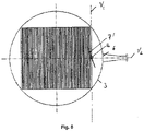
- the baffle plate 7 is arranged inclined relative to a first imaginary vertical plane V 1 being perpendicular to a second imaginary vertical plane V 2 comprising the inflow direction axis through the inlet opening. This is shown in Fig. 3 which is identical to Fig. 1 except for the shown imaginary planes.
- the second imaginary vertical plane V 2 is the plane of the drawing.
- the first imaginary vertical plane V 1 is shown perpendicular to this plane V 2 .
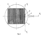
- the baffle plate 7 is inclined under an angle ⁇ such that it intersects said first imaginary vertical plane V 1 along a horizontal line H 1 .
- the horizontal line H 1 is also perpendicular to the second plane V 2 .
- Fig. 2 which shows the horizontal line H 1 perpendicular to the second plane V 2 and also shows the upper edge of the deflection element 7.
- the inclination ⁇ of the baffle plate 7 is the same as the inclination ⁇ ' of the sedimentation settler 2 (see Fig. 3 ).
- the baffle plate 7 extends in elongation of the lower end 21 of the sedimentation settler 2. In particular, it extends into the receiving chamber 4 at that lower edge 22 of the sedimentation settler 2 being closest to the inlet opening 6.
- the deflection element forms an extension of the outer surface of the sedimentation settler reaching into the collection vessel.
- the baffle plate 170 is connected to the inner wall of the collection vessel 130 above the inlet opening 160.
- a curved deflection plate 170 is shown but it may as well be straight as long as it is inclined relative to the horizontal.
- the inflow inlet opening 6 is located below the lower edge of the sedimentation settler 2.
- the sedimentation settler 2 comprises a plurality of plates 23 forming a plurality sedimentation channels in between.
- the sedimentation settler preferably has from 60 to 70 channels, preferably 65 or 66 channels.
- the temperature is automatically regulated by a double heating jacket in all cultivations.
- PH regulation is made by the addition of an alkaline solution (base) with peristaltic pumps as well as by the introduction of gaseous CO 2 via mass flows.
- Dissolved oxygen is automatically regulated by air and nitrogen, as well as the pressure and the stirring velocity.
- Antibody titers were quantified by high performance liquid chromatography (HPLC) using a Poros A affinity column.
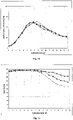
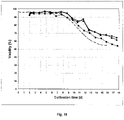
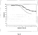
- the perfusion employed in the N-1 fermentation of the seed train does not influence cell growth of the cells in the thereafter following fermentations, i.e. no lag phase was identifiable.
Landscapes
- Chemical & Material Sciences (AREA)
- Life Sciences & Earth Sciences (AREA)
- Health & Medical Sciences (AREA)
- Engineering & Computer Science (AREA)
- Organic Chemistry (AREA)
- Zoology (AREA)
- Bioinformatics & Cheminformatics (AREA)
- Wood Science & Technology (AREA)
- Biotechnology (AREA)
- Sustainable Development (AREA)
- Microbiology (AREA)
- Biomedical Technology (AREA)
- Biochemistry (AREA)
- General Engineering & Computer Science (AREA)
- General Health & Medical Sciences (AREA)
- Genetics & Genomics (AREA)
- Chemical Kinetics & Catalysis (AREA)
- Molecular Biology (AREA)
- Apparatus Associated With Microorganisms And Enzymes (AREA)
- Control And Other Processes For Unpacking Of Materials (AREA)
- Extraction Or Liquid Replacement (AREA)
Applications Claiming Priority (3)
| Application Number | Priority Date | Filing Date | Title |
|---|---|---|---|
| EP11151110 | 2011-01-17 | ||
| EP12703463.5A EP2665806B1 (de) | 2011-01-17 | 2012-01-13 | Trennvorrichtung |
| PCT/EP2012/050508 WO2012098055A1 (en) | 2011-01-17 | 2012-01-13 | Separation apparatus and use thereof |
Related Parent Applications (1)
| Application Number | Title | Priority Date | Filing Date |
|---|---|---|---|
| EP12703463.5A Division EP2665806B1 (de) | 2011-01-17 | 2012-01-13 | Trennvorrichtung |
Publications (3)
| Publication Number | Publication Date |
|---|---|
| EP4036207A1 true EP4036207A1 (de) | 2022-08-03 |
| EP4036207C0 EP4036207C0 (de) | 2025-10-22 |
| EP4036207B1 EP4036207B1 (de) | 2025-10-22 |
Family
ID=44168237
Family Applications (2)
| Application Number | Title | Priority Date | Filing Date |
|---|---|---|---|
| EP21187619.8A Active EP4036207B1 (de) | 2011-01-17 | 2012-01-13 | Verwendung einer trennvorrichtung in seed train |
| EP12703463.5A Active EP2665806B1 (de) | 2011-01-17 | 2012-01-13 | Trennvorrichtung |
Family Applications After (1)
| Application Number | Title | Priority Date | Filing Date |
|---|---|---|---|
| EP12703463.5A Active EP2665806B1 (de) | 2011-01-17 | 2012-01-13 | Trennvorrichtung |
Country Status (9)
| Country | Link |
|---|---|
| US (4) | US20140057344A1 (de) |
| EP (2) | EP4036207B1 (de) |
| JP (2) | JP5995871B2 (de) |
| ES (1) | ES2890412T3 (de) |
| HR (1) | HRP20211494T1 (de) |
| PL (1) | PL2665806T3 (de) |
| SG (1) | SG191745A1 (de) |
| SI (1) | SI2665806T1 (de) |
| WO (1) | WO2012098055A1 (de) |
Families Citing this family (10)
| Publication number | Priority date | Publication date | Assignee | Title |
|---|---|---|---|---|
| EP4036207B1 (de) | 2011-01-17 | 2025-10-22 | F. Hoffmann-La Roche AG | Verwendung einer trennvorrichtung in seed train |
| TWI743024B (zh) | 2014-06-06 | 2021-10-21 | 美商健臻公司 | 灌注培養方法及其用途 |
| TWI707949B (zh) | 2014-06-09 | 2020-10-21 | 美商健臻公司 | 種子罐培養法(seed train processes)及其用途 |
| US9944894B2 (en) * | 2015-01-16 | 2018-04-17 | General Electric Company | Pluripotent stem cell expansion and passage using a rocking platform bioreactor |
| EP3714035A4 (de) * | 2017-11-22 | 2021-08-18 | Culture Biosciences, Inc. | Automationsarbeitszelle für fermentation |
| WO2019204044A1 (en) | 2018-04-18 | 2019-10-24 | Kompala Dhinakar S | Particle settling devices |
| EP3561038A1 (de) * | 2018-04-24 | 2019-10-30 | Bayer AG | Zellseparator |
| CN110935207B (zh) * | 2019-12-13 | 2020-10-09 | 安徽理工大学 | 一种紧凑式无耙浓缩装置 |
| US11679345B2 (en) | 2020-03-19 | 2023-06-20 | Sudhin Biopharma | Particle settling devices |
| US12227730B2 (en) * | 2020-11-18 | 2025-02-18 | Global Life Sciences Solutions Usa Llc | System and method for aseptic sampling and fluid addition |
Citations (4)
| Publication number | Priority date | Publication date | Assignee | Title |
|---|---|---|---|---|
| EP0003146A2 (de) | 1978-01-06 | 1979-07-25 | Ballast-Nedam Groep N.V. | Vorrichtung zur Behandlung von Abwasser mittels Schwerkrafttrennung |
| DE3619926A1 (de) | 1985-06-19 | 1987-01-02 | Euro Technical Oilservices Bv | Vorrichtung zur behandlung einer verunreinigungen enthaltenden fluessigkeit |
| EP0259928A1 (de) * | 1986-09-10 | 1988-03-16 | Recticel | Anlage zur anaeroben Gärung von Abfallwassern und Verfahren zu einer kombinierten, anaeroben/aeroben Gärung von Abfallwassern |
| WO2003020919A2 (en) | 2001-08-31 | 2003-03-13 | Bayer Healthcare Ag | A unit and a process for carrying out high cell density fermentation |
Family Cites Families (29)
| Publication number | Priority date | Publication date | Assignee | Title |
|---|---|---|---|---|
| US2967107A (en) * | 1957-03-04 | 1961-01-03 | John Labott Ltd | Continuous fermentation process |
| US3385439A (en) * | 1966-06-07 | 1968-05-28 | Niels B. Bach | Sedimentation method and apparatus |
| SE330151B (de) * | 1968-09-20 | 1970-11-09 | Nordstjernan Rederi Ab | |
| DE2139521B2 (de) * | 1971-08-06 | 1975-03-27 | Sybron Corp., Rochester, N.Y. (V.St.A.) | Schrägklärapparat |
| DE7138603U (de) * | 1971-10-12 | 1972-06-15 | Passavant Werke | Vorrichtung zur mechanisch-chemischen Wasseraufbereitung und Abwasserbehandlung |
| US3898162A (en) * | 1973-08-20 | 1975-08-05 | Andrew Carlson & Sons Inc | Septic tanks |
| US3897676A (en) * | 1973-09-10 | 1975-08-05 | Hercules Membrino | Opening device for thermoplastic bags |
| US4123365A (en) | 1974-08-14 | 1978-10-31 | Ballast-Nedam Groep N.V. | Oil-water separator |
| US4218325A (en) * | 1979-01-29 | 1980-08-19 | Mcmullin Edward J Jr | Apparatus for separation of suspensions |
| US4184954A (en) * | 1979-03-23 | 1980-01-22 | Peterson Albert C | Sedimentation device and method for purifying waste water |
| BE888016A (fr) | 1981-03-19 | 1981-09-21 | Acec | Bac de reaction pour reactif liquide |
| US4814278A (en) * | 1985-02-05 | 1989-03-21 | Teijin Limited | Culture apparatus and method |
| IL104385A (en) * | 1992-01-17 | 1995-12-31 | Applied Research Systems | Method and device for growing biomass particles |
| US5320963A (en) * | 1992-11-25 | 1994-06-14 | National Research Council Of Canada | Bioreactor for the perfusion culture of cells |
| GB9309429D0 (en) * | 1993-05-07 | 1993-06-23 | Bioscot Ltd | Fermenter accessory |
| US5874003A (en) * | 1997-06-25 | 1999-02-23 | Rose; Bryan L. | Wastewater treatment apparatus with floating clarifier |
| EP1689878A4 (de) * | 2003-11-03 | 2007-02-14 | Centocor Inc | Verfahren zur beibehaltung von geringer scherung in einem bioprozessierungssystem |
| FR2878912B1 (fr) * | 2004-12-07 | 2008-08-15 | Peugeot Citroen Automobiles Sa | Ensemble de suralimentation pour moteur a combustion interne et vehicule correspondant |
| FR2880548B1 (fr) | 2004-12-29 | 2007-08-10 | Sources Sa | Decanteur lamellaire destine au traitement des eaux usees et comportant un dispositif de recuperation des flottants |
| WO2007071072A1 (en) * | 2005-12-22 | 2007-06-28 | Corporation De L'ecole Polytechnique De Montreal | High-rate perfusion bioreactor |
| WO2008036600A2 (en) * | 2006-09-18 | 2008-03-27 | Genentech, Inc. | Methods of protein production |
| JP5226697B2 (ja) * | 2007-01-12 | 2013-07-03 | ダウ グローバル テクノロジーズ エルエルシー | 浸透圧によって細胞にショックを与えるための装置および方法 |
| ES2657055T3 (es) * | 2007-08-09 | 2018-03-01 | Wyeth Llc | Uso de perfusión para mejorar la producción de un cultivo de células alimentado por lotes en biorreactores |
| DE102008029307A1 (de) * | 2008-06-20 | 2009-12-24 | Bayer Technology Services Gmbh | Verfahren und Vorrichtung zur Rückhaltung und Rückführung von Zellen |
| US8114802B2 (en) * | 2008-12-30 | 2012-02-14 | Chevron U.S.A. Inc. | Heavy oil upgrade process including recovery of spent catalyst |
| US20110003331A1 (en) * | 2009-05-02 | 2011-01-06 | Thomas Clayton Pavia | Method for enhanced production of biofuels and other chemicals using biological organisms |
| US8580554B2 (en) * | 2009-07-31 | 2013-11-12 | Baxter International Inc. | Method of producing a polypeptide or virus of interest in a continuous cell culture |
| EP4036207B1 (de) * | 2011-01-17 | 2025-10-22 | F. Hoffmann-La Roche AG | Verwendung einer trennvorrichtung in seed train |
| SG11201404611RA (en) * | 2012-02-20 | 2014-09-26 | Bayer Technology Services Gmbh | One-way separator for retaining and recirculating cells |
-
2012
- 2012-01-13 EP EP21187619.8A patent/EP4036207B1/de active Active
- 2012-01-13 EP EP12703463.5A patent/EP2665806B1/de active Active
- 2012-01-13 JP JP2013548851A patent/JP5995871B2/ja active Active
- 2012-01-13 SI SI201231948T patent/SI2665806T1/sl unknown
- 2012-01-13 WO PCT/EP2012/050508 patent/WO2012098055A1/en not_active Ceased
- 2012-01-13 SG SG2013047493A patent/SG191745A1/en unknown
- 2012-01-13 HR HRP20211494TT patent/HRP20211494T1/hr unknown
- 2012-01-13 PL PL12703463T patent/PL2665806T3/pl unknown
- 2012-01-13 ES ES12703463T patent/ES2890412T3/es active Active
-
2013
- 2013-07-15 US US13/942,661 patent/US20140057344A1/en not_active Abandoned
-
2016
- 2016-08-23 JP JP2016162526A patent/JP6194080B2/ja active Active
-
2017
- 2017-02-23 US US15/440,350 patent/US10702800B2/en active Active
-
2020
- 2020-06-11 US US16/899,453 patent/US11697079B2/en active Active
-
2023
- 2023-05-25 US US18/202,208 patent/US12274960B2/en active Active
Patent Citations (4)
| Publication number | Priority date | Publication date | Assignee | Title |
|---|---|---|---|---|
| EP0003146A2 (de) | 1978-01-06 | 1979-07-25 | Ballast-Nedam Groep N.V. | Vorrichtung zur Behandlung von Abwasser mittels Schwerkrafttrennung |
| DE3619926A1 (de) | 1985-06-19 | 1987-01-02 | Euro Technical Oilservices Bv | Vorrichtung zur behandlung einer verunreinigungen enthaltenden fluessigkeit |
| EP0259928A1 (de) * | 1986-09-10 | 1988-03-16 | Recticel | Anlage zur anaeroben Gärung von Abfallwassern und Verfahren zu einer kombinierten, anaeroben/aeroben Gärung von Abfallwassern |
| WO2003020919A2 (en) | 2001-08-31 | 2003-03-13 | Bayer Healthcare Ag | A unit and a process for carrying out high cell density fermentation |
Non-Patent Citations (2)
| Title |
|---|
| BIOPRODUCTION CONFERENCE, 2010 |
| VOISARD, D. ET AL., BIOTECHNOL. BIOENG., vol. 82, 2003, pages 751 - 765 |
Also Published As
| Publication number | Publication date |
|---|---|
| US11697079B2 (en) | 2023-07-11 |
| JP2017006139A (ja) | 2017-01-12 |
| US20200406168A1 (en) | 2020-12-31 |
| EP2665806B1 (de) | 2021-07-28 |
| US20230294020A1 (en) | 2023-09-21 |
| JP6194080B2 (ja) | 2017-09-06 |
| SG191745A1 (en) | 2013-08-30 |
| EP4036207C0 (de) | 2025-10-22 |
| JP2014502511A (ja) | 2014-02-03 |
| JP5995871B2 (ja) | 2016-09-21 |
| US10702800B2 (en) | 2020-07-07 |
| US20140057344A1 (en) | 2014-02-27 |
| HRP20211494T1 (hr) | 2021-12-24 |
| EP2665806A1 (de) | 2013-11-27 |
| PL2665806T3 (pl) | 2021-12-27 |
| WO2012098055A1 (en) | 2012-07-26 |
| US12274960B2 (en) | 2025-04-15 |
| ES2890412T3 (es) | 2022-01-19 |
| EP4036207B1 (de) | 2025-10-22 |
| SI2665806T1 (sl) | 2021-11-30 |
| US20170157539A1 (en) | 2017-06-08 |
Similar Documents
| Publication | Publication Date | Title |
|---|---|---|
| US12274960B2 (en) | Separation apparatus and use thereof | |
| EP1451290B1 (de) | Vorrichtung und verfahren zur fermentation in hohen zelldichten | |
| EP3781281B1 (de) | Vorrichtungen zur partikelabsetzung | |
| AU664596B2 (en) | Method and apparatus for growing biomass particles | |
| AU2002333739A1 (en) | A unit and a process for carrying out high cell density fermentation | |
| CA2109897A1 (en) | Bioreactor for the perfusion culture of cells | |
| US20110097800A1 (en) | Method and apparatus for retaining and recirculating cells | |
| Hülscher et al. | Selective recycle of viable animal cells by coupling of airlift reactor and cell settler | |
| Kompala et al. | Optimization of high cell density perfusion bioreactors | |
| Tebbe et al. | Lysis-free separation of hybridoma cells by continuous disc stack centrifugation | |
| JPH06209761A (ja) | 細胞培養装置 | |
| Banik et al. | An investigation of cell density effects on hybridoma metabolism in a homogeneous perfusion reactor | |
| HK40043575B (en) | Particle settling devices | |
| SERRA | Continuous mammalian cell cultures: characterization and optimization of two perfusion systems | |
| HK1012674B (en) | Method and apparatus for growing biomass particles | |
| HK1073668B (en) | A unit and a process for carrying out high cell density fermentation |
Legal Events
| Date | Code | Title | Description |
|---|---|---|---|
| STAA | Information on the status of an ep patent application or granted ep patent |
Free format text: STATUS: UNKNOWN |
|
| PUAI | Public reference made under article 153(3) epc to a published international application that has entered the european phase |
Free format text: ORIGINAL CODE: 0009012 |
|
| STAA | Information on the status of an ep patent application or granted ep patent |
Free format text: STATUS: THE APPLICATION HAS BEEN PUBLISHED |
|
| AC | Divisional application: reference to earlier application |
Ref document number: 2665806 Country of ref document: EP Kind code of ref document: P |
|
| AK | Designated contracting states |
Kind code of ref document: A1 Designated state(s): AL AT BE BG CH CY CZ DE DK EE ES FI FR GB GR HR HU IE IS IT LI LT LU LV MC MK MT NL NO PL PT RO RS SE SI SK SM TR |
|
| STAA | Information on the status of an ep patent application or granted ep patent |
Free format text: STATUS: REQUEST FOR EXAMINATION WAS MADE |
|
| 17P | Request for examination filed |
Effective date: 20230202 |
|
| RBV | Designated contracting states (corrected) |
Designated state(s): AL AT BE BG CH CY CZ DE DK EE ES FI FR GB GR HR HU IE IS IT LI LT LU LV MC MK MT NL NO PL PT RO RS SE SI SK SM TR |
|
| GRAP | Despatch of communication of intention to grant a patent |
Free format text: ORIGINAL CODE: EPIDOSNIGR1 |
|
| STAA | Information on the status of an ep patent application or granted ep patent |
Free format text: STATUS: GRANT OF PATENT IS INTENDED |
|
| INTG | Intention to grant announced |
Effective date: 20250523 |
|
| GRAS | Grant fee paid |
Free format text: ORIGINAL CODE: EPIDOSNIGR3 |
|
| GRAA | (expected) grant |
Free format text: ORIGINAL CODE: 0009210 |
|
| STAA | Information on the status of an ep patent application or granted ep patent |
Free format text: STATUS: THE PATENT HAS BEEN GRANTED |
|
| AC | Divisional application: reference to earlier application |
Ref document number: 2665806 Country of ref document: EP Kind code of ref document: P |
|
| AK | Designated contracting states |
Kind code of ref document: B1 Designated state(s): AL AT BE BG CH CY CZ DE DK EE ES FI FR GB GR HR HU IE IS IT LI LT LU LV MC MK MT NL NO PL PT RO RS SE SI SK SM TR |
|
| REG | Reference to a national code |
Ref country code: CH Ref legal event code: F10 Free format text: ST27 STATUS EVENT CODE: U-0-0-F10-F00 (AS PROVIDED BY THE NATIONAL OFFICE) Effective date: 20251022 Ref country code: GB Ref legal event code: FG4D |
|
| RIN1 | Information on inventor provided before grant (corrected) |
Inventor name: BRAUNERSREUTHER, OSKAR Inventor name: JOCKWER, ALEXANDER Inventor name: KLABUHN, TORSTEN Inventor name: POHLSCHEIDT, MICHAEL Inventor name: THIELE, JOERG |
|
| REG | Reference to a national code |
Ref country code: DE Ref legal event code: R096 Ref document number: 602012081773 Country of ref document: DE |
|
| REG | Reference to a national code |
Ref country code: IE Ref legal event code: FG4D |
|
| U01 | Request for unitary effect filed |
Effective date: 20251103 |
|
| U07 | Unitary effect registered |
Designated state(s): AT BE BG DE DK EE FI FR IT LT LU LV MT NL PT RO SE SI Effective date: 20251107 |
|
| PGFP | Annual fee paid to national office [announced via postgrant information from national office to epo] |
Ref country code: GB Payment date: 20251220 Year of fee payment: 15 |
|
| U20 | Renewal fee for the european patent with unitary effect paid |
Year of fee payment: 15 Effective date: 20251217 |
|
| REG | Reference to a national code |
Ref country code: CH Ref legal event code: U11 Free format text: ST27 STATUS EVENT CODE: U-0-0-U10-U11 (AS PROVIDED BY THE NATIONAL OFFICE) Effective date: 20260201 |
|
| PG25 | Lapsed in a contracting state [announced via postgrant information from national office to epo] |
Ref country code: ES Free format text: LAPSE BECAUSE OF FAILURE TO SUBMIT A TRANSLATION OF THE DESCRIPTION OR TO PAY THE FEE WITHIN THE PRESCRIBED TIME-LIMIT Effective date: 20251022 |
|
| PG25 | Lapsed in a contracting state [announced via postgrant information from national office to epo] |
Ref country code: NO Free format text: LAPSE BECAUSE OF FAILURE TO SUBMIT A TRANSLATION OF THE DESCRIPTION OR TO PAY THE FEE WITHIN THE PRESCRIBED TIME-LIMIT Effective date: 20260122 |
|
| PG25 | Lapsed in a contracting state [announced via postgrant information from national office to epo] |
Ref country code: HR Free format text: LAPSE BECAUSE OF FAILURE TO SUBMIT A TRANSLATION OF THE DESCRIPTION OR TO PAY THE FEE WITHIN THE PRESCRIBED TIME-LIMIT Effective date: 20251022 |
|
| PG25 | Lapsed in a contracting state [announced via postgrant information from national office to epo] |
Ref country code: RS Free format text: LAPSE BECAUSE OF FAILURE TO SUBMIT A TRANSLATION OF THE DESCRIPTION OR TO PAY THE FEE WITHIN THE PRESCRIBED TIME-LIMIT Effective date: 20260122 |
|
| PG25 | Lapsed in a contracting state [announced via postgrant information from national office to epo] |
Ref country code: IS Free format text: LAPSE BECAUSE OF FAILURE TO SUBMIT A TRANSLATION OF THE DESCRIPTION OR TO PAY THE FEE WITHIN THE PRESCRIBED TIME-LIMIT Effective date: 20260222 |
|
| PGFP | Annual fee paid to national office [announced via postgrant information from national office to epo] |
Ref country code: CH Payment date: 20260201 Year of fee payment: 15 |
|
| PG25 | Lapsed in a contracting state [announced via postgrant information from national office to epo] |
Ref country code: PL Free format text: LAPSE BECAUSE OF FAILURE TO SUBMIT A TRANSLATION OF THE DESCRIPTION OR TO PAY THE FEE WITHIN THE PRESCRIBED TIME-LIMIT Effective date: 20251022 |