EP4036314A1 - Milling head for machining pile heads - Google Patents
Milling head for machining pile heads Download PDFInfo
- Publication number
- EP4036314A1 EP4036314A1 EP21154111.5A EP21154111A EP4036314A1 EP 4036314 A1 EP4036314 A1 EP 4036314A1 EP 21154111 A EP21154111 A EP 21154111A EP 4036314 A1 EP4036314 A1 EP 4036314A1
- Authority
- EP
- European Patent Office
- Prior art keywords
- central
- ring plate
- chisel
- milling
- rotation
- Prior art date
- Legal status (The legal status is an assumption and is not a legal conclusion. Google has not performed a legal analysis and makes no representation as to the accuracy of the status listed.)
- Withdrawn
Links
- 238000003801 milling Methods 0.000 title claims abstract description 151
- 238000003754 machining Methods 0.000 title claims description 7
- 230000008878 coupling Effects 0.000 claims abstract description 24
- 238000010168 coupling process Methods 0.000 claims abstract description 24
- 238000005859 coupling reaction Methods 0.000 claims abstract description 24
- 230000002787 reinforcement Effects 0.000 claims abstract description 20
- 229910052751 metal Inorganic materials 0.000 claims abstract description 9
- 239000002184 metal Substances 0.000 claims abstract description 8
- 239000000463 material Substances 0.000 description 50
- XEEYBQQBJWHFJM-UHFFFAOYSA-N Iron Chemical compound [Fe] XEEYBQQBJWHFJM-UHFFFAOYSA-N 0.000 description 20
- 230000035515 penetration Effects 0.000 description 17
- 229910052742 iron Inorganic materials 0.000 description 10
- 238000012423 maintenance Methods 0.000 description 5
- 230000002950 deficient Effects 0.000 description 4
- 238000010276 construction Methods 0.000 description 3
- 238000006073 displacement reaction Methods 0.000 description 3
- 230000009471 action Effects 0.000 description 2
- 238000005265 energy consumption Methods 0.000 description 2
- 238000009415 formwork Methods 0.000 description 2
- 238000009434 installation Methods 0.000 description 2
- 238000004901 spalling Methods 0.000 description 2
- 230000007704 transition Effects 0.000 description 2
- 229910000831 Steel Inorganic materials 0.000 description 1
- 230000006835 compression Effects 0.000 description 1
- 238000007906 compression Methods 0.000 description 1
- 238000005520 cutting process Methods 0.000 description 1
- 230000007547 defect Effects 0.000 description 1
- 238000005553 drilling Methods 0.000 description 1
- 230000000694 effects Effects 0.000 description 1
- 238000005516 engineering process Methods 0.000 description 1
- 230000006872 improvement Effects 0.000 description 1
- 238000004519 manufacturing process Methods 0.000 description 1
- 238000005297 material degradation process Methods 0.000 description 1
- 230000003014 reinforcing effect Effects 0.000 description 1
- 230000008439 repair process Effects 0.000 description 1
- 230000000717 retained effect Effects 0.000 description 1
- 239000002689 soil Substances 0.000 description 1
- 239000007787 solid Substances 0.000 description 1
- 239000010959 steel Substances 0.000 description 1
- 238000003466 welding Methods 0.000 description 1
Images





Classifications
-
- E—FIXED CONSTRUCTIONS
- E02—HYDRAULIC ENGINEERING; FOUNDATIONS; SOIL SHIFTING
- E02D—FOUNDATIONS; EXCAVATIONS; EMBANKMENTS; UNDERGROUND OR UNDERWATER STRUCTURES
- E02D5/00—Bulkheads, piles, or other structural elements specially adapted to foundation engineering
- E02D5/22—Piles
- E02D5/64—Repairing piles
-
- B—PERFORMING OPERATIONS; TRANSPORTING
- B28—WORKING CEMENT, CLAY, OR STONE
- B28D—WORKING STONE OR STONE-LIKE MATERIALS
- B28D1/00—Working stone or stone-like materials, e.g. brick, concrete or glass, not provided for elsewhere; Machines, devices, tools therefor
- B28D1/18—Working stone or stone-like materials, e.g. brick, concrete or glass, not provided for elsewhere; Machines, devices, tools therefor by milling, e.g. channelling by means of milling tools
- B28D1/186—Tools therefor, e.g. having exchangeable cutter bits
-
- E—FIXED CONSTRUCTIONS
- E02—HYDRAULIC ENGINEERING; FOUNDATIONS; SOIL SHIFTING
- E02D—FOUNDATIONS; EXCAVATIONS; EMBANKMENTS; UNDERGROUND OR UNDERWATER STRUCTURES
- E02D37/00—Repair of damaged foundations or foundation structures
-
- E—FIXED CONSTRUCTIONS
- E02—HYDRAULIC ENGINEERING; FOUNDATIONS; SOIL SHIFTING
- E02D—FOUNDATIONS; EXCAVATIONS; EMBANKMENTS; UNDERGROUND OR UNDERWATER STRUCTURES
- E02D5/00—Bulkheads, piles, or other structural elements specially adapted to foundation engineering
-
- E—FIXED CONSTRUCTIONS
- E02—HYDRAULIC ENGINEERING; FOUNDATIONS; SOIL SHIFTING
- E02D—FOUNDATIONS; EXCAVATIONS; EMBANKMENTS; UNDERGROUND OR UNDERWATER STRUCTURES
- E02D9/00—Removing sheet piles bulkheads, piles, mould-pipes or other moulds or parts thereof
-
- E—FIXED CONSTRUCTIONS
- E02—HYDRAULIC ENGINEERING; FOUNDATIONS; SOIL SHIFTING
- E02D—FOUNDATIONS; EXCAVATIONS; EMBANKMENTS; UNDERGROUND OR UNDERWATER STRUCTURES
- E02D9/00—Removing sheet piles bulkheads, piles, mould-pipes or other moulds or parts thereof
- E02D9/005—Removing sheet piles bulkheads, piles, mould-pipes or other moulds or parts thereof removing the top of placed piles of sheet piles
-
- B—PERFORMING OPERATIONS; TRANSPORTING
- B28—WORKING CEMENT, CLAY, OR STONE
- B28D—WORKING STONE OR STONE-LIKE MATERIALS
- B28D1/00—Working stone or stone-like materials, e.g. brick, concrete or glass, not provided for elsewhere; Machines, devices, tools therefor
- B28D1/18—Working stone or stone-like materials, e.g. brick, concrete or glass, not provided for elsewhere; Machines, devices, tools therefor by milling, e.g. channelling by means of milling tools
- B28D1/186—Tools therefor, e.g. having exchangeable cutter bits
- B28D1/188—Tools therefor, e.g. having exchangeable cutter bits with exchangeable cutter bits or cutter segments
Definitions
- the central drill and milling tools should also be able to be advantageously assembled and disassembled in the desired number, so that there is also less maintenance work in this regard and the milling head can be configured as required with little effort and adapted to the piles to be machined, which can have a diameter of more than 2 m can.
- the segments of the pile core and the pile casing can be removed by linearly lowering the milling head. Complex movements of a tool, which are difficult to execute and can lead to damage to the pile head, are no longer necessary. The processing of the pile head is therefore possible within a short time without causing any damage.
- the inner ring plate is preferably connected to the underside of a shank and the outer ring plate is connected to the underside of a mounting cylinder, the shank and the mounting cylinder being aligned coaxially with the axis of rotation and connected at the top to a coupling plate on which the coupling device is arranged.
- the mounting cylinder preferably includes at least one exit window through which the conveyed milling material can be discharged, and at least one mounting window which allows manual access to the coupling device, for example.
- the at least one conveyor spiral or two conveyor spirals preferably rotated by 180° relative to one another, is provided with a side wall in a lower section, which is preferably selected according to the height of the pile heads to be processed.
- the side wall ensures that the milled material in the lower section cannot escape from the spiral conveyors and from the remaining area of the pile head, which contains the Has reinforcement, can be promoted. Only after the milling material has been conveyed out of this area can it emerge laterally in an upper section of the conveying spiral, which is not provided with a side wall, and be guided out of the milling head via the at least one exit window.
- the central drill When operating the milling head, the central drill penetrates the core of the pile first.
- the central chisels then penetrate the pile core sequentially and in stages in pairs, so that the pile core is machined from the inside out.
- the surface tension of the pile core is broken step by step by arranging the central chisel in a stepped manner. Instead of rupturing the surface of the pile core in one step, the surface tension is broken gradually and thus with reduced force.
- the milling head according to the invention can therefore be operated efficiently with reduced force or reduced drive torques.
- the central chisel and ring chisel are preferably arranged in at least two spirally running rows and are mounted on the underside of the inner ring plate and the outer ring plate, respectively.
- the chisel height of the central chisel preferably increases, as described, linearly or non-linearly sequentially from central chisel to central chisel in the direction of the axis of rotation or in the direction of the central drill radially inwards.
- the invention therefore combines these three essential advantages, which are normally mutually exclusive. With reduced energy consumption, material is broken down faster and more gently. It should be noted that the milling process is promoted on the one hand by the disposal of the milling material according to the invention and on the other hand by the advantageous arrangement of the central chisel and/or ring chisel.
- the central chisels provided on the central milling machine and the ring chisels provided on the ring milling machine preferably consist of a holder that can be welded or mounted in a form-fitting manner and a chiseling element that can be inserted therein and that can be routinely replaced.
- the holders are preferably connected to the associated holders or assembly elements of the ring plates by means of form-fitting connections, for example dovetail connections.
- the ring chisels are preferably dimensioned somewhat larger than the central chisels. Further one of the ring bits can be connected to the inner ring plate as a clearing bit.
- the milling head is made of durable material, especially iron and steel.
- the tool parts that come into contact with the concrete pile are preferably made of hard metal.
- the milling tools include receiving openings are used in the hard metal elements that are used to machine the concrete.
- Plastic parts can be used if they have the desired strength and should give the milling head or parts of it a certain elasticity, for example.
- the ring milling machine 12 comprises an outer ring plate 122, on the underside of which ring bits 121 are mounted in the direction of rotation or inclined thereto.
- the upper side of the outer ring plate 122 is preferably detachably connected to the underside of a mounting cylinder 123, e.g. by means of flange elements and screws or threaded elements, the upper side of which is preferably detachably connected to the coupling plate 133, e.g. by means of flange elements and screws or threaded elements.
- the assembly cylinder 123 has a quarter section through which the view of the central milling machine 11 is uncovered.
- the assembly cylinder 123 has exit windows 1231 through which loosened milling material can be carried away to the outside.
- the assembly cylinder 123 has assembly windows 1232 on the upper side, which allow access to the milling head 1, e.g. in order to release the central milling machine 11.
- the outer ring plate 122 has an outside diameter d122o and an inside diameter d122i.
- the inner ring plate 112 has an outer diameter d112.
- the increase in the mounting height of the ring bit 121 is preferably in a range of 5 mm - 25 mm.
- the increase in mounting height of the first ring bits 1211, 1212, ... is close to 5 mm and the increase in mounting height of the last ring bits ..., 12111, 12112 is close to 25 mm.
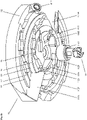
- Figure 5a shows the complete with central chisels 111; radial vanes 118A, 118B; conveyor blades 119A, 119B; clearing tools 1119A, 1119B; and the central drill 114 tipped inner ring plate 112 of Figure 3a in spatial representation.
- a series of central chisels 111 is provided with the associated serial numbers 1111, 1112, ..., 1108. Also shown on the right is a view over impeller blade 119B through transfer opening 1120B.
- the underside of the inner ring plate 112 is provided with annular steps S1, S2, S3, S4, S5, which preferably correspond to the working groups m1.
- the blade inclination angle a4 which is approximately 45° in the embodiment shown, is therefore selected in such a way that the milled material can reach the transfer opening 1020B via the conveyor blade 119B and on to the conveyor spiral 113B.
- the conveying blade 119B has an outer wall 119S so that the conveyed milling material cannot escape to the outside.
- the transfer surface 1125B is preferably shaped in such a way that a preferably laminar transition without obstacles results between the conveyor blade 119B at the entrance of the conveyor spiral 113B.
- Figure 6b shows the inner ring plate 112 of FIG Figure 6a without the feed spirals 113A, 113B, the shaft 115 and the feed blade 119B.
- a connection space with a connection surface 1127 is exposed at the lower edge of the transfer surface 1125B or on the underside of the transfer opening 1120B, in which the conveyor blade 119B is fastened. eg screwed and/or welded.
Landscapes
- Engineering & Computer Science (AREA)
- Structural Engineering (AREA)
- Mining & Mineral Resources (AREA)
- General Engineering & Computer Science (AREA)
- Paleontology (AREA)
- Civil Engineering (AREA)
- Life Sciences & Earth Sciences (AREA)
- General Life Sciences & Earth Sciences (AREA)
- Mechanical Engineering (AREA)
- Piles And Underground Anchors (AREA)
- Earth Drilling (AREA)
- Placing Or Removing Of Piles Or Sheet Piles, Or Accessories Thereof (AREA)
- Drilling And Boring (AREA)
Abstract
Der Fräskopf (1), welcher eine Drehachse (x) aufweist und der Bearbeitung eines Pfahlkopfs (80) eines Pfahles (8), der einen Pfahlkern (81), einen Pfahlmantel (82) und eine dazwischen liegende Metallarmierung (83) umfasst, dient, umfasst eine Kopplungsvorrichtung (13), die mit einer Antriebswelle (2) einer Antriebsvorrichtung verbindbar ist, eine Zentralfräse (11), die mehrere an der Unterseite einer Innenringplatte (112) montierte Zentralmeissel (111) aufweist, und eine Ringfräse (12), die mehrere an der Unterseite einer Aussenringplatte (122) montierte Ringmeissel (121) aufweist, welche Zentralfräse (11) und Ringfräse (12) koaxial zur Drehachse (x) ausgerichtet miteinander verbunden sind, wobei die Aussenringplatte (122) durch eine mittlere Kreisringfläche (kr2) davon getrennt die Innenringplatte (112) umschliesst. Erfindungsgemäss ist vorgesehen, dass die Innenringplatte (112) wenigstens eine von der Unterseite zur Oberseite der Innenringplatte (112) führende Transferöffnung (1120A, 1120B) aufweist, an die an der Unterseite eine zumindest teilweise in einen Arbeitsbereich der Zentralmeissel (111) hinein ragende Förderschaufel (119A, 119B) und an der Oberseite eine Förderspirale (113A, 113B) anschliesst.The milling head (1), which has an axis of rotation (x) and is used to machine a pile head (80) of a pile (8), which comprises a pile core (81), a pile casing (82) and metal reinforcement (83) lying in between , comprises a coupling device (13) which can be connected to a drive shaft (2) of a drive device, a central cutter (11) which has a plurality of central cutters (111) mounted on the underside of an inner ring plate (112), and a ring cutter (12), which has several ring bits (121) mounted on the underside of an outer ring plate (122), which central milling cutter (11) and ring milling cutter (12) are connected to one another, aligned coaxially to the axis of rotation (x), the outer ring plate (122) being connected to one another by a central annular surface (kr2 ) separately encloses the inner ring plate (112). According to the invention, the inner ring plate (112) has at least one transfer opening (1120A, 1120B) leading from the underside to the upper side of the inner ring plate (112), to which on the underside a conveyor blade protruding at least partially into a working area of the central chisel (111). (119A, 119B) and a conveyor spiral (113A, 113B) at the top.
Description
Aus der
Zu bearbeitende Betonpfähle dieser Art, die typischerweise bei instabilem Baugrund vorgesehen werden, um ein Bauobjekt zu stützen, bestehen aus Beton, der auf Druck belastbar ist, und Armierungseisen, das auf Zug belastbar ist. Die Abmessungen der Pfähle werden entsprechend dem Bauobjekt und dem Baugrund gewählt und können in einem weiten Bereich variieren. Typischerweise werden Pfähle mit Längen von 5 m - 50 m und Durchmessern von 0.4 m - 2.5 m eingesetzt. Für die Fertigung der Pfähle werden Bohrungen in den Untergrund eingefügt, in die Rohre eingesetzt werden. In die Rohre wird das Armierungseisen eingesetzt und der Beton eingefüllt. Erdmaterial, das sich am unteren Ende des Rohres befindet, wird dabei zumeist nach oben verdrängt und findet sich nach Fertigstellung des Pfahls in dessen Kopfbereich, weshalb dieser nicht die erforderliche Festigkeit aufweist. Ferner weist der Pfahl bzw. der Pfahlkopf normalerweise nicht die erforderlichen Abmessungen auf. Gegebenenfalls fehlen am Pfahlkopf auch für das Bauobjekt erforderliche Kopplungselemente. Der Pfahlkopf wird daher zumeist bearbeitet und in den erforderlichen Dimensionen und der notwendigen Qualität neu aufgebaut.To be worked concrete piles of this type, which are typically provided in unstable subsoil to support a building object, consist of concrete that can be loaded in compression and rebar that can be loaded in tension. The dimensions of the piles are chosen according to the building object and the building ground and can vary within a wide range. Typically, piles with lengths of 5 m - 50 m and diameters of 0.4 m - 2.5 m are used. For the manufacture of the piles, holes are drilled into the subsoil into which pipes are inserted. The reinforcing iron is inserted into the pipes and the concrete is poured in. Soil material that is located at the lower end of the pipe is usually pushed upwards and is found in the top area after the pile has been completed, which is why it does not have the required strength. Furthermore, the pile or the pile head usually does not have the required dimensions. If necessary, the coupling elements required for the construction project are missing at the pile head. The pile head is therefore usually processed and rebuilt in the required dimensions and quality.
Dazu wird der vorgefertigte, normalerweise zylinderförmige Pfahlkopf mittels eines Fräskopfs typischerweise über eine Länge im Bereich von 0.5 m - 1.5 m bearbeitet, um den mangelhaften Beton zu entfernen. Der Beton muss dabei derart entfernt werden, dass das typischerweise koaxial zur Drehachse des Pfahles typischerweise hülsenförmig angeordnete Armierungseisen sowie intakter Beton unterhalb des Pfahlkopfs nicht verletzt werden. Nach dem Entfernen des mangelhaften oder überschüssigen Betons und dem Freilegen der Armierung wird diese normalerweise durch eine ergänzende Armierung erweitert und mit einer Verschalung versehen, die den Dimensionen des neu zu erstellenden Pfahlkopfs entspricht. Die Verschalung wird anschliessend mit Beton gefüllt und nach der Verfestigung des Betons entfernt.To do this, the prefabricated, usually cylindrical, pile head is machined using a milling head, typically over a length in the range of 0.5 m - 1.5 m, in order to remove the defective concrete. The concrete must be removed in such a way that the rebar, which is typically arranged coaxially to the axis of rotation of the pile, is typically sleeve-shaped, and the intact concrete below the pile head is not damaged. After removing the defective or excess concrete and exposing the rebar, it is usually supplemented with additional rebar and formwork to match the dimensions of the new pile cap to be constructed. The formwork is then filled with concrete and removed after the concrete has hardened.
Traditionell wurde bei der Bearbeitung von Pfahlköpfen der Pfahlkern bis an den Rand des Armierungseisens ausgefräst. Anschliessend wurde der Pfahlmantel bis zur Eisenarmierung abgefräst. Diese Bearbeitung nahm in der Regel nicht nur viel Zeit in Anspruch genommen, sondern führte oft auch zu Verletzungen der Eisenarmierung. Ferner traten insbesondere bei der Bearbeitung des Pfahlmantels Abspaltungen des zuvor intakten Betons auf, durch die sich der zur Verfügung stehende Querschnitt des Betonpfahls erheblich reduzierte, sodass sich der vom Betonpfahl auf das aufgebaute Objekt übertragene Flächendruck entsprechend erhöhte. Entsprechende Schäden an einem Betonpfahl hatten daher oft erhebliche Folgeschäden an Objekt zur Folge, die auf mangelhaften Pfahlköpfen aufgebaut wurde. Zur Vermeidung solcher Folgeschäden mussten mangelhafte Pfähle und Pfahlköpfe daher mit grossem Aufwand und entsprechenden Kosten wieder instand gesetzt werden.Traditionally, when processing pile heads, the core of the pile was milled out to the edge of the reinforcement iron. The pile casing was then milled down to the iron reinforcement. This processing usually not only took a lot of time, but also often led to damage to the iron reinforcement. Furthermore, occurred in particular in the Processing of the pile shell caused the previously intact concrete to split, which significantly reduced the available cross-section of the concrete pile, so that the surface pressure transferred from the concrete pile to the built-up object increased accordingly. Corresponding damage to a concrete pile therefore often resulted in considerable consequential damage to an object that was built on defective pile heads. To avoid such consequential damage, defective piles and pile heads therefore had to be repaired at great expense and expense.
Bei der Bearbeitung von Pfahlköpfen spielt daher nicht nur der Zeitfaktor eine wichtige Rolle, sondern insbesondere auch die qualitativ hochwertige Fertigstellung der Pfahlköpfe, die eine Schlüsselstelle im Fundament des Bauwerks, z.B. eines Gebäudes oder einer Brücke, bilden.When processing pile heads, not only does the time factor play an important role, but also the high-quality finishing of the pile heads, which form a key point in the foundation of a structure, e.g. a building or a bridge.
Mit dem Fräskopf gemäss der
Trotz der deutlichen Verbesserung bei der Bearbeitung von Pfahlköpfen mit diesem Fräskopf erzielt wurde, blieb die Forderung bestehen, einen Fräskopf zu entwickeln, welcher es erlaubt, Pfahlköpfe noch schneller und noch schonender zu bearbeiten. Die Erhöhung der Arbeitsgeschwindigkeit einer Vorrichtung führt in der Regel jedoch zu qualitativ schlechteren Arbeitsergebnissen, was hinsichtlich der tragenden Bedeutung der bearbeiteten Objekte bzw. der Pfahlköpfe nicht zulässig ist.Despite the significant improvement in the processing of pile heads with this milling head, the demand remained to develop a milling head that allows pile heads to be processed even faster and more gently. However, increasing the working speed of a device usually leads to poorer quality work results, which is not permissible in view of the vital importance of the processed objects or the pile heads.
Der vorliegenden Erfindung liegt daher die Aufgabe zugrunde, einen verbesserten Fräskopf für die Bearbeitung von Pfahlköpfen zu schaffen.The present invention is therefore based on the object of creating an improved milling head for machining pile heads.
Mittels des Fräskopfs sollen Pfahlköpfe von Betonpfählen gleichzeitig mit reduzierter Kraft, mit höherer Arbeitsgeschwindigkeit und mit höherer Arbeitsqualität bearbeitet werden können. Der Fräskopf soll vorteilhafter in den Pfahlkopf, den Pfahlkern und den Pfahlmantel eindringen können, sodass Betonmaterial mit reduziertem Kraftaufwand abgetragen werden kann und durch die Reduktion des Kraftaufwands gleichzeitig das Risiko der Beschädigung des bearbeiteten Pfahlkopfs reduziert wird.By means of the milling head, pile heads of concrete piles should be able to be processed simultaneously with reduced force, at a higher working speed and with a higher quality of work. The milling head should be able to penetrate more advantageously into the pile head, the pile core and the pile shell, so that concrete material can be removed with less effort and by reducing the effort required, the risk of damage to the processed pile head is reduced at the same time.
Bei der Bearbeitung der Pfahlköpfe soll schonend auf den Beton eingewirkt werden, sodass bei einem beschleunigten Materialabtrag keine Spalten und Risse im Pfahlkopf resultieren. Gleichzeitig soll die Belastung der Fräswerkzeuge bzw. der Meissel reduziert werden, sodass sich auch der Wartungsaufwand für den Fräskopf entsprechend reduziert.When processing the pile heads, the concrete should be treated gently so that accelerated material removal does not result in gaps and cracks in the pile head. At the same time, the load on the milling tools or the chisel should be reduced, so that the maintenance effort for the milling head is reduced accordingly.
Mittels des Fräskopfs soll insbesondere sichergestellt werden, dass bei der Bearbeitung eines Pfahlkopfs keine Abspaltungen im Pfahlmantel erfolgen, welche je nach Grösse einen entsprechend hohen Reparaturaufwand zur Folge hätten.The milling head is intended in particular to ensure that the processing of a pile head does not result in any splitting of the pile shell, which, depending on the size, would result in correspondingly high repair costs.
Der Zentralbohrer und Fräswerkzeuge sollen zudem in gewünschter Anzahl vorteilhaft montierbar und demontierbar sein, sodass auch diesbezüglich ein geringer Wartungsaufwand resultiert und der Fräskopf mit geringem Aufwand bedarfsweise konfiguriert und an die zu bearbeitenden Pfähle, die einen Durchmesser von mehr als 2 m aufweisen können, angepasst werden kann.The central drill and milling tools should also be able to be advantageously assembled and disassembled in the desired number, so that there is also less maintenance work in this regard and the milling head can be configured as required with little effort and adapted to the piles to be machined, which can have a diameter of more than 2 m can.
Diese Aufgabe wird mit einem Fräskopf gelöst, welcher die in Anspruch 1 angegebenen Merkmale aufweist. Vorteilhafte Ausgestaltungen der Erfindung sind in weiteren Ansprüchen angegeben.This object is achieved with a milling head which has the features specified in
Der Fräskopf dient der Bearbeitung eines Pfahlkopfs eines Pfahls typischerweise eines Betonpfahls, der einen Pfahlkern, einen Pfahlmantel und eine Metallarmierung umfasst, die zwischen dem Pfahlkern und dem Pfahlmantel liegt.The milling head is used to machine a pile head of a pile, typically a concrete pile, which comprises a pile core, a pile casing and a metal reinforcement which lies between the pile core and the pile casing.
Der Fräskopf, der beim Betrieb um dessen Längsachse bzw. Drehachse gedreht wird, umfasst eine Kopplungsvorrichtung, die mit einer Antriebswelle einer Antriebsvorrichtung verbindbar ist, eine Zentralfräse, die mehrere an der Unterseite einer Innenringplatte montierte Zentralmeissel aufweist, und eine Ringfräse, die mehrere an der Unterseite einer Aussenringplatte montierte Ringmeissel aufweist, welche Zentralfräse und Ringfräse koaxial zur Drehachse ausgerichtet miteinander verbunden sind, wobei die Aussenringplatte durch eine mittlere Kreisringfläche davon getrennt die Innenringplatte umschliesst.The milling head, which is rotated about its longitudinal axis or axis of rotation during operation, comprises a coupling device which can be connected to a drive shaft of a drive device, a central milling machine which has a number of central chisels mounted on the underside of an inner ring plate, and a ring milling machine which has a number of central chisels mounted on the underside of an inner ring plate Underside of an outer ring plate has ring bits mounted, which central milling cutter and ring milling cutter are aligned coaxially to the axis of rotation and are connected to one another, the outer ring plate enclosing the inner ring plate separated from it by a central annular surface.
Erfindungsgemäss ist vorgesehen, dass die Innenringplatte wenigstens eine von der Unterseite zur Oberseite der Innenringplatte führende Transferöffnung aufweist, an die an der Unterseite eine zumindest teilweise in einen Arbeitsbereich der Zentralmeissel hinein ragende Förderschaufel und an der Oberseite eine Förderspirale anschliesst.According to the invention, it is provided that the inner ring plate has at least one transfer opening leading from the underside to the upper side of the inner ring plate, to which an at least partially conveying blade projecting into a working area of the central chisel and adjoining a conveying spiral on the upper side.
Mit dem erfindungsgemässen Fräskopf gelingt es, Segmente des Pfahlkerns und des Pfahlmantels gleichzeitig abzutragen, ohne dass die im Bereich der mittleren Kreisringfläche liegende Armierung des Pfahls beschädigt wird. Die Bearbeitung erfolgt mit hoher Präzision, so dass der Beton selbst in geringem Abstand von wenigen Zentimetern von der Armierung abgetragen werden kann. Die verbleibende dünne Betonhülse, in der die Armierung eingeschlossen ist, kann anschliessend mittels eines weiteren Werkzeugs, z.B. mittels einer Zange, rasch abgetragen werden.With the milling head according to the invention it is possible to remove segments of the pile core and the pile casing simultaneously without damaging the reinforcement of the pile lying in the area of the central annular surface. The processing is carried out with high precision, so that the concrete can be removed even at a short distance of a few centimeters from the reinforcement. The remaining thin concrete sleeve, in which the reinforcement is enclosed, can then be quickly removed using another tool, e.g. pliers.
Besonders vorteilhaft ist, dass die Segmente des Pfahlkerns und des Pfahlmantels durch eine lineare Absenkung des Fräskopfs abgetragen werden können. Komplexe Bewegungen eines Werkzeugs, die schwierig auszuführen sind und zu Beschädigungen des Pfahlkopfs führen können, entfallen. Die Bearbeitung des Pfahlkopfs gelingt daher innerhalb kurzer Zeit ohne Schäden zu verursachen.It is particularly advantageous that the segments of the pile core and the pile casing can be removed by linearly lowering the milling head. Complex movements of a tool, which are difficult to execute and can lead to damage to the pile head, are no longer necessary. The processing of the pile head is therefore possible within a short time without causing any damage.
Aufgrund der linearen Verschiebung des Fräskopfs und den entsprechend kalkulierbaren Krafteinwirkungen auf die Werkzeuge, reduzieren sich auch die Belastungen und der Verschleiss des Fräskopfs, weshalb eine Wartung nur in grösseren Intervallen notwendig.Due to the linear displacement of the milling head and the correspondingly calculable force effects on the tools, the loads and wear on the milling head are also reduced, which is why maintenance is only necessary at longer intervals.
Die wenigstens eine Förderschaufel, die in den Arbeitsbereich der Meissel hineinragt, erlaubt es, das vom Betonkern abgetragene Fräsmaterial zu erfassen und durch die zugehörige Transferöffnung der zugehörigen Förderspirale zuzuführen. Durch den Abtransport des Fräsmaterials wird ein wesentliches Arbeitshindernis aus dem Arbeitsbereich der Meissel entfernt, weshalb der Fräskopf mit reduziertem Widerstand drehen kann und die Zentralmeissel mit reduziertem Widerstand in den Pfahlkern eindringen können. Einerseits erhöht sich die Wirksamkeit der Fräswerkzeuge und andererseits reduziert sich deren Belastung.The at least one conveyor shovel, which protrudes into the working area of the chisel, allows the milled material removed from the concrete core to be grasped and fed through the associated transfer opening to the associated conveyor spiral. By removing the milled material, a major obstacle to work is removed from the working area of the chisel, which is why the milling head can turn with reduced resistance and the central chisel can penetrate the pile core with reduced resistance. On the one hand, the effectiveness of the milling tools increases and, on the other hand, their load is reduced.
Mittels des erfindungsgemässen Fräskopfs wird somit ein gezielter Materialfluss realisiert, der den Fräsprozess entlastet und ein effizientes Abtragen des Pfahlkerns und des Pfahlmantels erlaubt. Aufgrund des gezielten Materialflusses durch die wenigstens eine Transferöffnung kann die Innenringplatte ansonsten mit einem grossen Flächenanteil für die Montage von Zentralmeisseln genutzt werden. Durch die grosse Montagefläche der Innenringplatte wird der Materialfluss daher nicht beeinträchtigt. An der Unterseite der Innenringplatte können daher Zentralmeissel in der gewünschten Anzahl montiert werden.By means of the milling head according to the invention, a targeted flow of material is thus implemented, which relieves the milling process and allows efficient removal of the pile core and the pile casing. Due to the targeted flow of material through the at least one transfer opening, the inner ring plate can otherwise be used with a large surface area for the assembly of central chisels. The material flow is therefore not affected by the large mounting surface of the inner ring plate. The desired number of central chisels can therefore be mounted on the underside of the inner ring plate.
Besonders effizient kann das Fräsmaterial abgetragen werden, wenn die Innenringplatte mit zwei Transferöffnungen versehen wird, an die an der Unterseite je eine zumindest teilweise in den Arbeitsbereich der Zentralmeissel hinein ragende Förderschaufel und an der Oberseite je eine Förderspirale anschliesst. Damit das Fräsmaterial mit minimalem Widerstand in die Förderspiralen fliessen kann, wird vorzugsweise vorgesehen, dass an jede Transferöffnung eine Anschlussfläche an der Oberseite der Innenringplatte anschliesst, welche einen laminaren oder hindernisfreien Übergang von der Förderschaufel zur zugehörigen Förderspirale gewährleistet.The milled material can be removed particularly efficiently if the inner ring plate is provided with two transfer openings, each of which is connected to a conveyor blade at least partially protruding into the working area of the central chisel on the underside and a conveyor spiral on the top. So that the milled material can flow into the conveyor spirals with minimal resistance, it is preferably provided that a connecting surface on the upper side of the inner ring plate connects to each transfer opening, which ensures a laminar or unobstructed transition from the conveyor blade to the associated conveyor spiral.
Vorzugsweise liegen die Transferöffnungen und die Förderschaufeln und die Zentralmeissel einander in Bezug auf die Drehachse paarweise diametral und in gleichen Abständen von der Drehachse gegenüber. Die Förderschaufeln, die Zentralmeissel und die Ringmeissel liegen vorzugsweise ebenfalls paarweise auf gleicher Höhe. Auf diese Weise wird gewährleistet, dass die einander diametral gegenüber liegenden Werkzeuge bzw. Meissel stets in gleicher Weise auf den Pfahlkopf einwirken und durch Asymmetrien verursachte störende Momente oder Kräfte, die den Fräskopf und dessen Führung belasten könnten, vermieden werden. Der Fräskopf kann daher optimal geführt und mit minimalem Kraftaufwand betrieben werden. Seitlich auf den Fräskopf einwirkende Kräfte, welche für die installierten Werkzeuge, wie die Meissel und den vorzugsweise vorgesehenen Zentralbohrer, ungünstig sein könnten, werden vermieden.Preferably, the transfer openings and the conveying blades and the center cutter are diametrically opposed in pairs with respect to the axis of rotation and at equal distances from the axis of rotation. The conveying blades, the central chisel and the ring chisel are preferably also in pairs at the same height. This ensures that the diametrically opposed tools or chisels always act on the pile head in the same way and that disturbing moments or forces caused by asymmetries that could stress the milling head and its guide are avoided. The milling head can therefore be optimally guided and operated with minimal effort. Forces acting laterally on the milling head, which could be unfavorable for the installed tools, such as the chisel and the preferably provided central drill, are avoided.
Vorzugsweise ist die Innenringplatte mit der Unterseite eines Schafts und die Aussenringplatte mit der Unterseite eines Montagezylinders verbunden, wobei der Schaft und der Montagezylinder, koaxial zur Drehachse ausgerichtet und an der Oberseite mit einer Kopplungsplatte verbunden sind, an der die Kopplungsvorrichtung angeordnet ist. Der Montagezylinder umfasst vorzugsweise wenigstens ein Austrittsfenster, durch das das geförderte Fräsmaterial abgeführt werden kann, und wenigstens ein Montagefenster, welches den manuellen Zugriff beispielsweise zu Kopplungsvorrichtung erlaubt.The inner ring plate is preferably connected to the underside of a shank and the outer ring plate is connected to the underside of a mounting cylinder, the shank and the mounting cylinder being aligned coaxially with the axis of rotation and connected at the top to a coupling plate on which the coupling device is arranged. The mounting cylinder preferably includes at least one exit window through which the conveyed milling material can be discharged, and at least one mounting window which allows manual access to the coupling device, for example.
In einer weiteren vorzugsweisen Ausgestaltung ist vorgesehen, dass die wenigstens eine Förderspirale oder zwei vorzugsweise um 180° gegeneinander gedrehte Förderspiralen in einem unteren Abschnitt, der vorzugsweise entsprechend der Höhe der zu bearbeitenden Pfahlköpfe gewählt ist, mit einer Seitenwand versehen ist. Durch die Seitenwand wird sichergestellt, dass das Fräsmaterial im unteren Abschnitt nicht von den Förderspiralen entweichen kann und aus dem verbleibenden Bereich des Pfahlkopfs, der die Armierung aufweist, heraus gefördert werden kann. Erst nachdem das Fräsmaterial aus diesem Bereich heraus gefördert wurde, kann es in einem oberen Abschnitt der Förderspirale, der nicht mit einer Seitenwand versehen ist, seitlich austreten und über das wenigstens eine Austrittsfenster aus den Fräskopf weggeführt werden. Die Seitenwand der Förderspirale sichert somit den Materialtransport von der Innenringplatte bis zu einem Bereich der Förderspirale, in dem das Fräsmaterial seitlich weggeführt wird. Die Seitenwand kann einstückig an der z.B. aus Metallblech gefertigten Förderspirale angeformt oder auch angeschweisst sein.In a further preferred embodiment it is provided that the at least one conveyor spiral or two conveyor spirals, preferably rotated by 180° relative to one another, is provided with a side wall in a lower section, which is preferably selected according to the height of the pile heads to be processed. The side wall ensures that the milled material in the lower section cannot escape from the spiral conveyors and from the remaining area of the pile head, which contains the Has reinforcement, can be promoted. Only after the milling material has been conveyed out of this area can it emerge laterally in an upper section of the conveying spiral, which is not provided with a side wall, and be guided out of the milling head via the at least one exit window. The side wall of the spiral conveyor thus ensures that the material is transported from the inner ring plate to an area of the spiral conveyor where the milled material is guided away to the side. The side wall can be formed in one piece on the conveyor spiral, which is made of sheet metal, for example, or it can also be welded.
An der Unterseite der Innenringplatte ist vorzugsweise ein koaxial zur Drehachse ausgerichteter Zentralbohrer angeordnet, der die Zentralmeissel und die Ringmeissel in Fräsrichtung überragt, und daher als erster in den Pfahlkopf bzw. den Pfahlkern eindringt und dadurch eine Führungsfunktion oder Pilotfunktion wahrnimmt und sicherstellt, dass die Zentralmeissel und Ringmeissel kreisförmigen Arbeitsverläufen folgen können.On the underside of the inner ring plate, a central drill is preferably arranged coaxially to the axis of rotation, which protrudes beyond the central chisel and the ring chisel in the milling direction, and is therefore the first to penetrate the pile head or the pile core, thereby performing a guiding function or pilot function and ensuring that the central chisel and ring chisels can follow circular working paths.
In weiteren vorzugsweisen Ausgestaltungen ist vorgesehen, dass an der Unterseite der Innenringplatte wenigstens eine an den Zentralbohrer anschliessende Radialschaufel vorgesehen ist, die mit Bezug auf die Drehachse vorzugsweise zumindest annähernd radial ausgerichtet ist. Vorzugsweise verläuft die zumindest eine Radialschaufel vom Zentralbohrer zur zumindest einen Transferöffnung. Vorzugsweise ist daher jeder Transferöffnung eine Radialschaufel zugeordnet. Durch die wenigstens eine Radialschaufel, die beispielsweise eine gerade oder gekrümmte Platte ist, wird sichergestellt, dass vom Zentralbohrer und von radial innenliegenden Zentralmeisseln freigelegtes Fräsmaterial nach aussen gegen die zugehörige Transferöffnung geführt wird. Der Verlauf der Unterkante oder Frontkante der Radialschaufel, ebenso wie der Verlauf der Unterkante oder Frontkante der Förderschaufel, ist dabei derart gewählt, dass eine Kontaktierung des Pfahlkerns stets vermieden wird. Die Radialschaufel wird von den benachbarten Zentralmeisseln daher in Förderrichtung überragt.In further preferred configurations, it is provided that at least one radial vane is provided on the underside of the inner ring plate, which adjoins the central drill and which is preferably aligned at least approximately radially with respect to the axis of rotation. The at least one radial vane preferably runs from the central drill to the at least one transfer opening. A radial vane is therefore preferably assigned to each transfer opening. The at least one radial blade, which is for example a straight or curved plate, ensures that milled material exposed by the central drill and by radially inner central chisels is guided outwards towards the associated transfer opening. The course of the lower edge or front edge of the radial blade, as well as the course of the lower edge or front edge of the conveying blade, is selected in such a way that contact with the pile core is always avoided. The radial vane is therefore surmounted by the adjacent central chisels in the conveying direction.
Die Innenringplatte kann erfindungsgemäss zahlreiche Funktionen vorteilhaft erfüllen. An der Unterseite der Innenringplatte können Montageöffnungen zur Aufnahme der Zentralmeissel und/oder der Radialschaufeln und/oder eine Aufnahmeöffnung zur Aufnahme eines Montageteils oder Bohrfutters, welches dem lösbaren Halten des Zentralbohrers dient, vorgesehen werden. Das Bohrfutter umfasst beispielsweise ein Arretierteil, mittels dessen der Zentralbohrer im Bohrfutter fixierbar und bedarfsweise wieder lösbar ist.According to the invention, the inner ring plate can advantageously fulfill numerous functions. Mounting openings for accommodating the central chisel and/or the radial blades and/or a receiving opening for accommodating an assembly part or drill chuck, which is used to detachably hold the central drill, can be provided on the underside of the inner ring plate. The drill chuck includes, for example, a locking part, by means of which the central drill can be fixed in the drill chuck and, if necessary, released again.
An der Oberseite der Innenringplatte kann eine Aufnahmeöffnung zur Aufnahme des Schafts vorgesehen werden, welcher die Innenringplatte mit der Kopplungsvorrichtung verbindet.A receiving opening can be provided on the upper side of the inner ring plate for receiving the shaft which connects the inner ring plate to the coupling device.
Die Verbindung des Montageteils oder Bohrfutters und des Schafts mit der Innenringplatte kann durch bekannte mechanische Verbindungstechnik, wie durch einen Presssitz und/oder durch ein Gewinde erfolgen. Für die Montage der Zentralmeissel sind vorzugsweise Halterungen vorgesehen, die in die Montageöffnungen eingesetzt werden. Die Zentralmeissel und der Zentralbohrer können daher vorteilhaft mit der Innenringplatte verbunden werden, weshalb Wartungsarbeiten vorteilhaft ausgeführt werden können. Im Falle eines Defekts oder einer notwendigen Wartung sind daher keine Schweissarbeiten notwendig. Stattdessen können die Zentralmeissel und der Zentralbohrer in einfacher Weise gelöst und ersetzt werden.The assembly part or drill chuck and the shank can be connected to the inner ring plate by known mechanical connection technology, such as by a press fit and/or by a thread. Brackets are preferably provided for the assembly of the central chisel, which are inserted into the assembly openings. The central chisel and the central drill can therefore advantageously be connected to the inner ring plate, which is why maintenance work can be carried out advantageously. In the event of a defect or necessary maintenance, no welding work is necessary. Instead, the center chisel and center drill can be easily detached and replaced.
In weiteren vorzugsweisen Ausgestaltungen ist vorgesehen, dass die Zentralmeissel je in gleichen oder ungleichen Meisselabständen auf Kreislinien bzw. Arbeitskreisen liegend radial voneinander beabstandet sind, wobei der einheitliche Meisselabstand bzw. die unterschiedlichen Meisselabstände zwischen den Arbeitskreisen vorzugsweise in einem Bereich von 20 mm - 40 mm liegen.In further preferred configurations, it is provided that the central chisels are spaced radially from each other at equal or unequal chisel spacings on circular lines or working circles, with the uniform chisel spacing or the different chisel spacings between the working circles preferably being in a range of 20 mm - 40 mm .
Beim Betrieb bzw. der Rotation des Fräskopfs um die Drehachse verlaufen die Zentralmeissel vorzugsweise paarweise und einander paarweise diametral gegenüberliegend in gleichen Arbeitskreisen, die voneinander beabstandet sind. Durch den radialen Abstand der Zentralmeissel oder der Arbeitskreise in einem Bereich von 20 mm - 40 mm erfolgt ein besonders effizientes Abtragen des Materials des Pfahlkerns. Bei grösseren Abständen als 40 mm wird zu wenig Material abgetragen und bei geringeren Abständen als 20 mm erfolgt ein Eindringen der Zentralmeissel nur unter wesentlich erhöhter Krafteinwirkung die vorzugsweise vermieden wird, um Beschädigungen des Pfahlkopfs und des Fräskopfs zu vermeiden. Idealerweise liegt der Meisselabstand etwa bei 25 mm - 35 mm.During operation or rotation of the milling head about the axis of rotation, the central chisels preferably run in pairs and in pairs diametrically opposite one another in the same working circles that are spaced apart from one another. Due to the radial spacing of the central chisel or the working circles in a range of 20 mm - 40 mm, the material of the pile core is removed particularly efficiently. If the distance is greater than 40 mm, too little material is removed and if the distance is less than 20 mm, the central chisel only penetrates under the action of a significantly increased force, which is preferably avoided in order to prevent damage to the pile head and the milling head. Ideally, the chisel spacing is around 25 mm - 35 mm.
Die Innenringplatte ist vorzugsweise gegenüber der Aussenringplatte nach vorn in Fräsrichtung versetzt, sodass auch die Zentralmeissel gegenüber den Ringmeisseln nach vorn versetzt sind. Beispielsweise liegt eine axiale Verschiebung von 10 mm - 25 mm vor.The inner ring plate is preferably offset forwards in the milling direction relative to the outer ring plate, so that the central bits are also offset forwards relative to the ring bits. For example, there is an axial displacement of 10 mm - 25 mm.
Alternativ oder zusätzlich ist vorzugsweise vorgesehen, dass die Montagehöhe der Zentralmeissel in Fräsrichtung von Arbeitskreis zu Arbeitskreis um eine Höhendifferenz ändert, die in einem Bereich von 5 mm - 25 mm liegt, und in Richtung zur Drehachse ansteigt.Alternatively or additionally, it is preferably provided that the mounting height of the central chisel in the milling direction changes from working group to working group by a height difference that is in a range of 5 mm - 25 mm and increases in the direction of the axis of rotation.
Beim Betrieb des Fräskopfs dringt daher zuerst der Zentralbohrer in den Pfahlkern ein. Anschliessend dringen sequenziell und abgestuft die Zentralmeissel paarweise in den Pfahlkern ein, sodass der Pfahlkern von innen nach aussen bearbeitet wird. Durch abgestufte Anordnung der Zentralmeissel wird die Oberflächenspannung des Pfahlkerns daher schrittweise gebrochen. Anstatt die Oberfläche des Pfahlkerns in einem Schritt aufzureissen, wird die Oberflächenspannung schrittweise und somit mit reduzierter Kraft gebrochen. Der erfindungsgemässe Fräskopf kann daher mit reduzierter Kraft bzw. reduzierten Antriebsmomenten effizient betrieben werden.When operating the milling head, the central drill penetrates the core of the pile first. The central chisels then penetrate the pile core sequentially and in stages in pairs, so that the pile core is machined from the inside out. The surface tension of the pile core is broken step by step by arranging the central chisel in a stepped manner. Instead of rupturing the surface of the pile core in one step, the surface tension is broken gradually and thus with reduced force. The milling head according to the invention can therefore be operated efficiently with reduced force or reduced drive torques.
In einer weiteren vorzugsweisen Ausgestaltung sind die Montagehöhen der Ringmeissel in Fräsrichtung ebenfalls unterschiedlich gewählt. Vorzugsweise steigt die Montagehöhe in Fräsrichtung von Ringmeissel zu Ringmeissel bzw. von Arbeitskreis zu Arbeitskreis der Ringmeissel radial nach aussen schrittweise mit einer Höhendifferenz an, die vorzugsweise in einem Bereich von 5 mm - 25 mm liegt.In a further preferred embodiment, the mounting heights of the ring bits are also selected to be different in the milling direction. The assembly height preferably increases in the milling direction from ring chisel to ring chisel or from working group to working group of ring chisels radially outward step by step with a height difference which is preferably in a range of 5 mm - 25 mm.
Da die am äussersten Rand der Aussenringplatte liegenden Ringmeissel am weitesten in Fräsrichtung nach unten gegen den Pfahlkopf verschoben sind, wird zuerst der äusserste Rand des Pfahlmantels abgefräst. Der Pfahlmantel wird daher von aussen nach innen abgefräst, wodurch Abspaltungen vermieden werden. Die Oberflächenspannung des Pfahlmantels wird daher an der Aussenkante gebrochen, wonach der Pfahlmantel nach innen schrittweise abgebaut wird.Since the ring bits on the outermost edge of the outer ring plate have been pushed furthest down in the direction of milling against the pile head, the outermost edge of the pile casing is milled off first. The pile casing is therefore milled from the outside inwards, which avoids spalling. The surface tension of the pile mantle is therefore broken at the outer edge, after which the pile mantle gradually degrades towards the inside.
Die Zentralmeissel und Ringmeissel sind vorzugsweise in wenigstens zwei spiralförmig verlaufenden Reihen angeordnet an der Unterseite der Innenringplatte bzw. der Aussenringplatte montiert. Die Meisselhöhe der Zentralmeissel erhöht sich vorzugsweise, wie beschrieben, linear oder nicht linear sequenziell von Zentralmeissel zu Zentralmeissel in Richtung zur Drehachse bzw. in Richtung zum Zentralbohrer radial nach innen. Die Meisselhöhe der Ringmeissel erhöht sich hingegen vorzugsweise, wie beschrieben, linear oder nicht linear sequenziell von Ringmeissel zu Ringmeissel bis zum Rand der Aussenringplatte radial nach aussen.The central chisel and ring chisel are preferably arranged in at least two spirally running rows and are mounted on the underside of the inner ring plate and the outer ring plate, respectively. The chisel height of the central chisel preferably increases, as described, linearly or non-linearly sequentially from central chisel to central chisel in the direction of the axis of rotation or in the direction of the central drill radially inwards. The chisel height of the ring chisel, on the other hand, preferably increases, as described, linearly or non-linearly sequentially from ring chisel to ring chisel up to the edge of the outer ring plate radially outwards.
Der Zentralbohrer und die auf unterschiedlichen Montagehöhen liegenden Zentralmeissel und die auf unterschiedlichen Montagehöhen liegenden Ringmeissel bzw. bilden in ihrem Eingriffsbereich bzw. mit den entsprechenden Arbeitskreisen eine konzentrisch zur Drehachse verlaufende Wellenform, die im Bereich der Drehachse in Fräsrichtung ein Maximum aufweist, die im Bereich der mittleren Kreisringfläche ein Minimum aufweist und die gegen den Aussenrand der Aussenringplatte in Fräsrichtung wieder ansteigt. Die Wellenform gewährleistet ein optimales Eingreifen des Fräskopfs in den Pfahlkopf, der dadurch effizient, aber auch schonend bearbeitet werden kann. Die Oberflächenspannungen im Pfahlkern und in Pfahlmantel werden vorteilhaft gebrochen, weshalb mit reduziertem Energieaufwand ein rascher Materialabbau erfolgt und gleichzeitig Beschädigungen, wie Abspaltungen des Pfahlmantels vermieden werden. Die Erfindung vereinigt daher diese drei wesentlichen Vorteile, die sich normalerweise gegenseitig ausschliessen. Mit reduziertem Energieaufwand erfolgt ein rascherer und schonenderer Materialabbau. Zu beachten ist, dass der Fräsprozess einerseits durch die erfindungsgemässe Entsorgung des Fräsmaterials und andererseits durch die vorteilhafte Anordnung der Zentralmeissel und/oder der Ringmeissel begünstigt wird.The central drill and the central chisels at different installation heights and the ring chisels at different installation heights form in their engagement area or with the corresponding working circles a wave form running concentrically to the axis of rotation, which has a maximum in the area of the axis of rotation in the milling direction, which in the area of the middle annular surface has a minimum and which rises again towards the outer edge of the outer ring plate in the milling direction. The wave shape ensures that the milling head engages optimally in the pile head, which means that it can be processed efficiently but also gently. The surface tensions in the pile core and in the pile shell are advantageously broken, which is why rapid material degradation takes place with reduced energy consumption and at the same time damage such as splitting off of the pile shell is avoided. The invention therefore combines these three essential advantages, which are normally mutually exclusive. With reduced energy consumption, material is broken down faster and more gently. It should be noted that the milling process is promoted on the one hand by the disposal of the milling material according to the invention and on the other hand by the advantageous arrangement of the central chisel and/or ring chisel.
Die wenigstens eine Förderschaufel weist eine Frontkante auf, die von einer der Drehachse näher liegenden Innenkante bis zu einer der Drehachse entfernter liegenden Aussenkante verläuft. Die Förderschaufel oder die Förderschaufeln sind dabei derart angeordnet und ausgerichtet, dass eine Kontaktierung des Pfahlkopfs vermieden und das gelöste Fräsmaterial sicher erfasst und effizient an die zugeordnete Förderspirale überführt wird. Das Fräsmaterial, welches von den Radialschaufeln radial von innen zu den Transferöffnungen nach aussen gefördert wird, wird von den Förderschaufeln aufgefangen und nach oben zu den Förderspiralen gefördert. Das von den aussen liegenden Zentralmeisseln gelöste Fräsmaterial wird von den Förderschaufeln hingegen zuerst aussen erfasst und in einen Materialfluss überführt, der nach innen und nach oben zu den Förderspiralen verläuft. Dadurch wird verhindert, dass sich Fräsmaterial peripher an der Innenringplatte sammelt und den Fräsprozess bzw. die Drehung des Fräskopfs behindert. Damit das von der Förderschaufel erfasste Material nicht durch Zentrifugalkräfte nach aussen geschleudert wird, weisen die Förderschaufeln vorzugsweise aussenliegende Schaufelwände auf.The at least one conveyor blade has a front edge that runs from an inner edge that is closer to the axis of rotation to an outer edge that is further away from the axis of rotation. The conveyor shovel or the conveyor shovels are arranged and aligned in such a way that contact with the pile head is avoided and the loosened milled material is reliably grasped and efficiently transferred to the associated conveyor spiral. The milled material, which is conveyed radially outwards from the inside to the transfer openings by the radial blades, is caught by the conveying blades and conveyed upwards to the conveying spirals. The milled material loosened by the central chisels on the outside, on the other hand, is first picked up from the outside by the conveyor shovels and transferred into a material flow that runs inwards and upwards to the conveyor spirals. This prevents milling material from collecting peripherally on the inner ring plate and impeding the milling process or the rotation of the milling head. So that the material seized by the conveyor shovel is not thrown outwards by centrifugal forces, the conveyor shovels preferably have external shovel walls.
In vorzugsweisen Ausgestaltungen ist daher zusätzlich ein wenigstens ein Räumungswerkzeug, z.B. ein Meissel, vorgesehen, welches Material an der Peripherie der Innenringplatte erfasst und nach innen ablenkt. Das Räumungswerkzeug oder der Räumungsmeissel überragt die Innenringplatte vorzugsweise um eine Räumungsbreite, die vorzugsweise in einem Bereich von 5mm - 40 mm liegt, radial nach aussen.In preferred configurations, at least one clearing tool, e.g. a chisel, is therefore additionally provided, which grasps material on the periphery of the inner ring plate and deflects it inwards. The broaching tool or the broaching chisel preferably protrudes radially outwards beyond the inner ring plate by a broaching width which is preferably in a range of 5 mm to 40 mm.
Vorzugsweise ist die Frontkante der Förderschaufeln gegenüber dem Durchmesser der Innenringplatte horizontal um einen horizontalen Neigungswinkel derart geneigt, dass bei der Rotation des Fräskopfs in Arbeitsrichtung die Aussenkante der betreffenden Förderschaufel vorläuft und die Innenkante nachläuft. Der horizontale Neigungswinkel, der vorzugsweise in einem Bereich von 5° - 25° liegt, stellt sicher, dass das Fräsmaterial peripher erfasst und gegen die Mitte der Förderschaufel geführt wird.Preferably, the front edge of the conveying blades is inclined horizontally relative to the diameter of the inner ring plate by a horizontal angle of inclination such that when the milling head rotates in In the working direction, the outer edge of the conveying blade in question is leading and the inner edge is trailing. The horizontal angle of inclination, which is preferably in a range of 5° - 25°, ensures that the milled material is gripped peripherally and guided towards the center of the conveyor bucket.
Vorzugsweise ist die Frontkante der Förderschaufeln gegenüber dem Durchmesser der Innenringplatte vertikal um einen vertikalen Neigungswinkel derart geneigt, dass die Innenkante vorzugsweise entsprechend dem Verlauf der Montagehöhe der Zentralmeissel höher liegt als die Aussenkante. Der vertikale Neigungswinkel ist entsprechend dem Höhenverlauf der Zentralmeissel vorzugsweise derart gewählt, dass zwischen den Spitzen der Zentralmeissel und der Frontkante der Förderschaufeln ein Schaufelabstand bzw. ein Abstand von den Meisselspitzen und demnach von der Oberfläche des Pfahlkerns im Bereich von 5 mm - 40 mm resultiert.The front edge of the conveying blades is preferably inclined vertically at a vertical angle of inclination relative to the diameter of the inner ring plate in such a way that the inner edge is preferably higher than the outer edge, corresponding to the course of the mounting height of the central chisel. The vertical angle of inclination is preferably chosen according to the height profile of the central chisel in such a way that between the tips of the central chisel and the front edge of the conveyor blades there is a blade spacing or a distance from the chisel tips and therefore from the surface of the pile core in the range of 5 mm - 40 mm.
Die Förderschaufeln sind ferner um einen vertikalen Schaufelneigungswinkel gegenüber der Drehachse geneigt, wobei die Frontkante der Förderschaufeln beim Betrieb des Fräskopfs vorauseilt und der vertikale Schaufelneigungswinkel vorzugsweise in einem Bereich zwischen 5° und 85° liegt.The conveyor blades are also inclined by a vertical blade inclination angle relative to the axis of rotation, the front edge of the conveyor blades leading the way during operation of the milling head and the vertical blade inclination angle preferably being in a range between 5° and 85°.
Die wenigstens eine Radialschaufel und/oder die wenigstens eine Förderschaufel sind vorzugsweise zumindest teilweise formschlüssig je in einer Ausnehmung oder Montageöffnung, die in der Innenringplatte vorgesehen ist, gehalten. Auf diese Weise können die Radialschaufeln und die Förderschaufeln einfach montiert und demontiert werden. Die wenigstens eine Radialschaufel und/oder die wenigstens eine Förderschaufel können hingegen auch ganz oder teilweise mit der Innenringplatte verschweisst werden, wobei vorzugsweise vorgesehen ist, dass die Radialschaufel und die Förderschaufel zumindest teilweise flächig an einer Stützfläche der Innenringplatte anliegen.The at least one radial vane and/or the at least one conveying vane are preferably held at least partially in a form-fitting manner in a recess or assembly opening provided in the inner ring plate. In this way, the radial blades and the conveyor blades can be assembled and disassembled easily. The at least one radial vane and/or the at least one conveying vane can, however, also be fully or partially welded to the inner ring plate, it preferably being provided that the radial vane and the conveying vane bear at least partially flat against a support surface of the inner ring plate.
Die an der Zentralfräse vorgesehenen Zentralmeissel und die an der Ringfräse vorgesehenen Ringmeissel bestehen vorzugsweise aus einer verschweissbaren oder formschlüssig montierbaren Halterung sowie einem darin einsetzbaren Meisselelement, das routinemässig ersetzt werden kann. Vorzugsweise sind die Halterungen mittels formschlüssiger Verbindungen, z.B. Schwalbenschwanzverbindungen, mit den zugehörigen Halterungen oder Montageelementen der Ringplatten verbunden. Die Ringmeissel sind vorzugsweise etwas grösser dimensioniert als die Zentralmeissel. Ferner kann einer der Ringmeissel als Räumungsmeissel mit der Innenringplatte verbunden sein.The central chisels provided on the central milling machine and the ring chisels provided on the ring milling machine preferably consist of a holder that can be welded or mounted in a form-fitting manner and a chiseling element that can be inserted therein and that can be routinely replaced. The holders are preferably connected to the associated holders or assembly elements of the ring plates by means of form-fitting connections, for example dovetail connections. The ring chisels are preferably dimensioned somewhat larger than the central chisels. Further one of the ring bits can be connected to the inner ring plate as a clearing bit.
Der Innen- und der Aussendurchmesser der inneren Ringplatte und der äusseren Ringplatte sind vorzugsweise präzise an die Abmessungen des Pfahles und die Position der Armierung im Pfahl angepasst, so dass ein maximaler Abtrag von Beton gewährleistet ist, ohne die Armierung zu verletzen. Der Fräskopf wird daher entsprechend den Dimensionen des zu bearbeitenden Pfahlkopfs bereitgestellt, der einen Aussendurchmesser von über 2 m aufweisen kann.The inside and outside diameters of the inner ring plate and the outer ring plate are preferably precisely adapted to the dimensions of the pile and the position of the reinforcement in the pile, so that maximum removal of concrete is ensured without damaging the reinforcement. The milling head is therefore provided according to the dimensions of the pile head to be processed, which can have an outside diameter of over 2 m.
Vorzugsweise sind Zentralfräsen und Ringfräsen in beliebigen Dimensionen miteinander kombinierbar bzw. durch die Kopplungsplatte miteinander verbindbar. Ferner sind vorzugsweise unterschiedlich dimensionierte und/oder unterschiedlich mit Werkzeugen bestückte Aussenringplatten mit dem Montagezylinder lösbar verbindbar. Ferner sind vorzugsweise unterschiedlich dimensionierte und/oder unterschiedlich mit Werkzeugen bestückte Innenringplatten mit dem Schaft lösbar verbindbar. Auf diese Weise kann der Fräskopf flexibel an die zu bearbeitenden Pfahlköpfe angepasst werden.Central milling and ring milling can preferably be combined with one another in any dimensions or connected to one another by the coupling plate. Furthermore, outer ring plates with different dimensions and/or differently equipped with tools can be releasably connected to the assembly cylinder. Furthermore, preferably differently dimensioned inner ring plates and/or differently equipped with tools can be releasably connected to the shank. In this way, the milling head can be flexibly adapted to the pile heads to be processed.
Der Fräskopf wird aus widerstandsfähigem Material, insbesondere Eisen und Stahl gefertigt. Die mit dem Betonpfahl in Kontakt tretenden Werkzeugteile werden vorzugsweise aus Hartmetall gefertigt. Typischerweise umfassen die Fräswerkzeuge Aufnahmeöffnungen, in die Hartmetallelemente eingesetzt werden, die der Bearbeitung des Betons dienen. Der Einsatz von Kunststoffteilen ist möglich, falls diese über die gewünschte Festigkeit verfügen und dem Fräskopf oder Teilen davon z.B. eine gewisse Elastizität verleihen sollen.The milling head is made of durable material, especially iron and steel. The tool parts that come into contact with the concrete pile are preferably made of hard metal. Typically, the milling tools include receiving openings are used in the hard metal elements that are used to machine the concrete. Plastic parts can be used if they have the desired strength and should give the milling head or parts of it a certain elasticity, for example.
Nachfolgend wird die Erfindung anhand von Zeichnungen näher erläutert. Dabei zeigt:
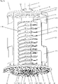
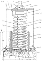
- Fig. 1a
- in Schnittdarstellung einen erfindungsgemässen Fräskopf 1 zur
Bearbeitung von Pfahlköpfen 80 mit einerKopplungsvorrichtung 13, mit einerRingfräse 12, die mehrere an der Unterseite einerAussenringplatte 122montierte Ringmeissel 12 aufweist, und mit einerZentralfräse 11, dieeine Innenringplatte 112 aufweist, anderen Unterseite 112mehrere Zentralmeissel 111 vorgesehen sowie zweiFörderschaufeln Transferöffnungen Arbeitsbereich der Zentralmeissel 111zu Förderspiralen - Fig. 1b
den Fräskopf 1 vonFig. 1a während der Bearbeitung eines Pfahlkopfs 80,dessen Pfahlkern 81 und Pfahlmantel 82, zwischen denen die unbeschädigte Eisenarmierung 83 in einer relativ dünnen Betonhülse 88 gehalten ist, bereits in der Höhe h2 abgetragen wurden;- Fig. 2
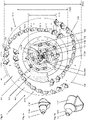
den Fräskopf 1 vonFig. 1a von unten mit Blick auf diemit den Zentralmeisseln 111 bestückte Innenringplatte 112 und diemit den Ringmeisseln 121bestückte Aussenringplatte 122, die entsprechend der Geometrie des bearbeiteten Pfahls 8eine dem Pfahlkern 81 entsprechende zentrale Kreisringfläche kr1 und eine dem Pfahlmantel 82 entsprechende äussere Kreisringfläche kr3 abdecken und eine mittlere Kreisringfläche kr2 begrenzen, in welche eine nach der Bearbeitung des Pfahlkopfs 80verbliebene Betonhülse 88mit der Eisenarmierung 83 eintreten kann;- Fig. 3a
- die
Innenringplatte 112 vonFig. 2 , diemit zwei Serien spiralförmig angeordneten Zentralmeisseln 111,einem Zentralbohrer 114 bestückt undmit zwei Transferöffnungen je eine Radialschaufel je eine Förderschaufel je ein Räumungsmeissel - Fig. 3b
- die
Innenringplatte 112 vonFig. 3a mit eingezeichneten Arbeitskreisen ml der beidenSerien 111B von Zentralmeisseln 111, von denen je zwei, die einander bezüglich der Drehachse x des Fräskopfs 1 bzw.des Zentralbohrers 114 diametral gegenüber liegen, entlang einem gemeinsamen Arbeitskreis ml geführt werden; - Fig. 4
- einen Teil der Zentralfräse 11
mit der Innenringplatte 112,dem Zentralbohrer 114, nur drei montierten Zentralmeisseln 1112A, 1115B, 1118A und einer derTransferöffnungen 1120B, an diedie zugehörige Radialschaufel 118B unddie zugehörige Förderschaufel 119B, die in denArbeitsbereich der Zentralmeissel 111 hineinragen, angrenzen; - Fig. 5a
- die
vollständig mit Zentralmeisseln 111,Radialschaufeln Förderschaufeln Räumungswerkzeugen und dem Zentralbohrer 114bestückte Innenringplatte 112 vonFig. 3a in räumlicher Darstellung; - Fig. 5b
- die
Innenringplatte 112 vonFig. 5a nach Entfernung derZentralmeissel 111 und derFörderschaufel 119B sowie der Entnahme desZentralbohrers 114mitsamt Bohrfutter 1143 aus einerAusnehmung 1129der Innenringplatte 112; - Fig. 6a
- die
Innenringplatte 112 vonFig. 5a von oben mit den an dieOberseite der Innenringplatte 112anschliessenden Förderspiralen gedreht den Schaft 115der Zentralfräse 11 umlaufen und die in diesem Abschnitt je mit einerSpiralwand 1130 versehen sind, sowie inFrontansicht die Transferöffnung 1120B, an die an der Unterseite die in denArbeitsbereich der Zentralmeissel 111hinein ragende Förderschaufel 119B und an die an derOberseite die Förderspirale 113B anschliesst; - Fig. 6b
- die
Innenringplatte 112 vonFig. 6a mit den Transferöffnungen Förderspiralen den Schaft 115und die Förderschaufel 119B; - Fig. 7a
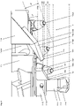
einen Zentralmeissel 111, der eineHalterung 111F und eindarin eingesetztes Meisselelement 111M umfasst; und- Fig. 7b
einen Ringmeissel 121, der eineHalterung 121F und eindarin eingesetztes Meisselelement 121M umfasst.
- Fig. 1a
- a sectional view of a
milling head 1 according to the invention for machining pile heads 80 with acoupling device 13, with aring milling machine 12, which has a plurality ofring bits 12 mounted on the underside of anouter ring plate 122, and with acentral milling machine 11, which has aninner ring plate 112, on its underside 112 a plurality ofcenter cutters 111 are provided and two conveyingblades adjacent transfer openings central chisel 111 to thespiral conveyors - Fig. 1b
- the
milling head 1 fromFig. 1a during the processing of apile head 80, thepile core 81 and pile shell 82, between which theundamaged iron reinforcement 83 is held in a relatively thinconcrete sleeve 88, have already been removed at the height h2; - 2
- the
milling head 1 fromFig. 1a from below with a view of theinner ring plate 112 fitted with thecentral chisels 111 and theouter ring plate 122 fitted with the ring chisels 121, which cover a central circular ring surface kr1 corresponding to thepile core 81 and an outer circular ring surface kr3 corresponding to the pile casing 82 in accordance with the geometry of the machined pile 8 and delimit a central annular surface kr2, into which aconcrete sleeve 88 with theiron reinforcement 83 remaining after the machining of thepile head 80 can enter; - Figure 3a
- the
inner ring plate 112 of2 , which is equipped with twoseries central chisels 111, acentral drill 114 and is provided with twotransfer openings radial blade blade clearing chisel - Figure 3b
- the
inner ring plate 112 ofFigure 3a with marked working circles m1 of the twoseries central chisels 111, of which two each, which are diametrically opposite one another with respect to the axis of rotation x of themilling head 1 or thecentral drill 114, are guided along a common working circle m1; - 4
- a part of the
central milling machine 11 with theinner ring plate 112, thecentral drill 114, only three mountedcentral chisels transfer openings 1120B, adjoined by the associatedradial blade 118B and the associated conveyingblade 119B, which protrude into the working area of thecentral chisel 111; - Figure 5a
- the
inner ring plate 112 of FIGFigure 3a in spatial representation; - Figure 5b
- the
inner ring plate 112 ofFigure 5a after removing thecentral chisel 111 and the conveyingblade 119B and removing thecentral drill 114 together with thedrill chuck 1143 from arecess 1129 in theinner ring plate 112; - Figure 6a
- the
inner ring plate 112 ofFigure 5a from above with the conveyor spirals 113A, 113B adjoining the upper side of theinner ring plate 112, which encircle theshaft 115 of thecentral milling cutter 11 rotated by 180° in relation to one another and which are each provided with aspiral wall 1130 in this section, as well as a front view of thetransfer opening 1120B theconveyor blade 119B protruding into the working area of thecentral chisel 111 on the underside and theconveyor spiral 113B on the upper side; - Figure 6b
- the
inner ring plate 112 ofFigure 6a withtransfer ports shaft 115 andconveyor blade 119B; - Figure 7a
- a
center chisel 111 comprising amount 111F and achisel element 111M inserted therein; and - Figure 7b
- a
ring bit 121 comprising aholder 121F and abit element 121M inserted therein.
Der Fräskopf 1 umfasst eine Zentralfräse 11 und eine Ringfräse 12, die an deren Oberseite durch eine Kopplungsplatte 133 und eine Konterplatte 134 miteinander sowie mit einer Kopplungsvorrichtung 13 verbunden sind. Die Kopplungsvorrichtung 13 umfasst eine Kopplungshülse 131, in die eine Antriebswelle 2 einer Antriebsvorrichtung (nicht gezeigt) einsetzbar und z.B. mittels eines Bolzens 132 arretierbar ist. Die Antriebswelle 2 ist beispielsweise von einem Baufahrzeug gehalten, das in der Lage ist, die Antriebswelle 2 um eine Drehachse x bzw. um die Längsachse des Fräskopfs 1 zu drehen und axial zu verschieben. Der Fräskopf 1 kann daher drehend koaxial auf einen Pfahlkopf 80 abgesenkt werden, um diesen zu bearbeiten, wie dies
Die Ringfräse 12 umfasst eine Aussenringplatte 122, an deren Unterseite Ringmeissel 121 in Drehrichtung ausgerichtet oder geneigt dazu montiert sind. Die Oberseite der Aussenringplatte 122 ist z.B. mittels Flanschelementen und Schrauben oder Gewindeelementen vorzugsweise lösbar mit der Unterseite eines Montagezylinders 123 verbunden, dessen Oberseite z.B. mittels Flanschelementen und Schrauben oder Gewindeelementen vorzugsweise lösbar mit der Kopplungsplatte 133 verbunden ist. Der Montagezylinder 123 weist einen Viertelschnitt auf, durch den die Sicht auf die Zentralfräse 11 freigelegt ist. An der Unterseite weist der Montagezylinder 123 Austrittsfenster 1231 auf, durch die gelöstes Fräsmaterial nach aussen weggeführt werden kann. An der Oberseite weist der Montagezylinder 123 Montagefenster 1232 auf, die einen Eingriff in den Fräskopf 1 erlauben, z.B. um die Zentralfräse 11 zu lösen.The
Die Zentralfräse 11 umfasst eine Innenringplatte 112, an deren Unterseite Zentralmeissel 111 in Drehrichtung ausgerichtet oder geneigt dazu montiert sind. Koaxial zur Drehachse x ausgerichtet ist an der Unterseite der Innenringplatte 112 ein Zentralbohrer 114 vorgesehen, welcher die Zentralmeissel 111 und die Ringmeissel 121 nach unten in Fräsrichtung überragt. Die Innenringplatte 112 weist ferner zwei Transferöffnungen 1020A, 1020B auf (siehe
An der Oberseite schliesst je eine Förderspirale 113A, 113B an die Transferöffnungen 1020A, 1020B an. Die Förderspiralen 113A, 113B, die nach oben einen Schaft 115 umschliessen, werden vorzugsweise aus einem massiven Blech geformt. Die Unterseite des Schafts 115 ist mit der Innenringplatte 112 verbunden und an der Oberseite von einer Verbindungsvorrichtung 14 vorzugsweise lösbar gehalten. Der Schaft 115 ist mittels der Verbindungsvorrichtung 14 kraftschlüssig und/oder formschlüssig mit der Kopplungsvorrichtung 13 verbunden. Die Verbindungsvorrichtung 14 umfasst vorzugsweise entlang dem Umfang des Schafts 115 verteilt angeordnete Spannvorrichtungen, die es erlauben, den Schaft 115 mit der Konterplatte 134 zu verspannen. Die Verbindungsvorrichtung 14 erlaubt es somit, den Schaft 115 und somit die Zentralfräse 11 vom Fräskopf 1 zu lösen. Die Zentralfräse 11 kann daher gelöst, gewartet und wieder eingesetzt oder durch eine Zentralfräse 11, die andere Eigenschaften aufweist, ersetzt werden.A
Nach Abschluss der Bearbeitung des Pfahlkopfs 80 wird der Fräskopf 1 wieder angehoben. Die verbliebene Betonhülse 88, welche die Eisenarmierung 83 noch immer umschliesst und schützt, wird anschliessend mit weiterem Werkzeug, wie Fräsen und Klemmen, mit geringem Aufwand beseitigt.After the processing of the
Die Aussenringplatte 122 hat einen Aussendurchmesser d122o und einen Innendurchmesser d122i. Die Innenringplatte 112 hat einen Aussendurchmesser d112.The
Auf der Aussenringplatte 122 sind drei Serien 121A, 121B, 121C von je zwölf spiralförmig angeordneten Ringmeisseln 121 bzw. 1211, 1212, ..., 12112 je um 120° versetzt angeordnet. Je drei Ringmeissel 121 folgen jeweils demselben Arbeitskreis ml (nur ein Arbeitskreis ml gezeigt). Die Montagehöhe der Ringmeissel 121 steigt vom ersten Ringmeissel 1211 bis zum letzten Ringmeissel 12112 oder von einem Arbeitskreis ml zum nächsten Arbeitskreis ml radial von innen nach aussen vorzugsweise stetig an, weshalb die äussersten Ringmeissel 12112 in Fräsrichtung am höchsten liegen und daher zuerst den äusseren Rand des Pfahlmantels 82 erfassen. Auf diese Weise wird der Pfahlmantel 82 von aussen nach innen bearbeitet, weshalb schädigende Abspaltungen vermieden werden. Der Anstieg der Montagehöhe der Ringmeissel 121 liegt vorzugsweise in einem Bereich von 5 mm - 25 mm. Beispielsweise liegt der Anstieg Montagehöhe der ersten Ringmeissel 1211, 1212, ... nahe bei 5 mm und der Anstieg der Montagehöhe der letzten Ringmeissel ..., 12111, 12112 nahe bei 25 mm.On the
Auf der Innenringplatte 112, die in
Wie
Beispielsweise liegt der Anstieg Montagehöhe der ersten Ringmeissel 1111, 1112, ... nahe bei 5 mm und der Anstieg der Montagehöhe der letzten Ringmeissel ..., 1107, 1108 nahe bei 25 mm.For example, the increase in mounting height of the
Die Zentralmeissel 111 sind paarweise je in gleichen oder ungleichen Meisselabständen ma radial gegeneinander versetzt und definieren bei der Drehung je einen Arbeitskreis ml. Die Differenz der Radien der Arbeitskreise ml entspricht dem jeweiligen Meisselabstand. Der einheitliche Meisselabstand ma bzw. die unterschiedlichen Meisselabstände ma liegen bevorzugt in einem Bereich von 20 mm - 40 mm. Bei dieser Anordnung der Zentralmeissel wird das Material optimal abgetragen. Die Arbeitskreise ml sind somit radial und auch in der Höhe gegeneinander versetztThe
Die Innenringplatte 112 weist zudem zwei in Bezug auf die Drehachse x einander diametral gegenüber liegende Transferöffnungen 1120A, 1120B auf, durch die das gelöste Fräsmaterial weggeführt werden kann. Zum Abtransport des Fräsmaterials sind angrenzend an die nachlaufende Kante jeder der Transferöffnungen 1120A, 1120B eine Förderschaufel 119A, 119B vorgesehen, die sich einerseits teilweise in den Bereich der jeweiligen Transferöffnung 1120A, 1120B und anderseits teilweise in den Arbeitsbereich der Zentralmeissel 111 erstrecken. Frontseitig weisen die Förderschaufeln 119A, 119B eine Frontkante 1193 auf, die von einer Innenkante zu einer Aussenkante der Förderschaufeln 119A, 119B verläuft. Die Förderschaufeln 119A, 119B greifen daher mit der Frontkante 1193 zuerst in das freigelegte Fräsmaterial ein, um dieses über die Förderschaufeln 119A, 119B nach oben wegzuführen.The
Jeder der Transferöffnungen 1120A, 1120B ist zudem eine Radialschaufel 118A, 118B zugeordnet, die das vom Zentralbohrer 114 und von den innenliegenden Zentralmeisseln 111 freigelegte Fräsmaterial nach aussen zu den Transferöffnungen 1120A, 1120B fördert. Die Radialschaufeln 118A, 118B können einfache Platten sein, die vorzugsweise formschlüssig von der Innenringplatte 112 gehalten und vorzugsweise radial oder geneigt gegen die zugehörige Transferöffnung 1120A, 1120B ausgerichtet sind.In addition, each of the
Damit das Fräsmaterial peripher gut erfasst werden kann, können auch die Förderschaufeln 119A, 119B die Innenringplatte 112 radial nach aussen um bis zu 35 mm überragen.So that the milled material can be grasped well at the periphery, the conveying
Die Frontkante 1183 der Radialschaufel 118B verläuft von der Innenkante 1181 zur Aussenkante 1182 bzw. von der Eindringtiefe t1181 zur Eindringtiefe t1182 mit einer abfallenden Neigung nach aussen. Die Frontkante 1193 der Förderschaufel 119B verläuft von der Innenkante 1191 zur Aussenkante 1192 bzw. von der Eindringtiefe t1191 zur Eindringtiefe t1182 mit einer abfallenden Neigung nach aussen.The
Die Frontkante 1193 der Förderschaufel 119B ist gegenüber dem Durchmesser d112 der Innenringplatte 112 vertikal vorzugsweise um einen vertikalen Neigungswinkel a2 derart geneigt, dass die Innenkante 1191 vorzugsweise entsprechend dem Verlauf der Montagehöhen der Zentralmeissel 111 in Förderrichtung höher liegt als die Aussenkante 1192. Die Förderschaufel 119B kann daher nicht in Kontakt mit der Oberfläche des Pfahlkopfs 80 bzw. des Pfahlkerns 81 geraten.The
Vorzugsweise ist zwischen der Frontkante 1193 der Förderschaufel 119 und den Arbeitskreisen ml der Zentralmeissel 111 bzw. den Spitzen der Zentralmeissel 111 ein Schaufelabstand a3 vorgesehen, der in einem Bereich von vorzugsweise 5 mm - 40 mm liegt.A blade distance a3 is preferably provided between the
Zur Realisierung der Montagehöhen bzw. zur gegenseitigen vertikalen Verschiebung der Zentralmeissel 111 ist die Unterseite der Innenringplatte 112 mit ringförmig verlaufenden Stufen S1, S2, S3, S4, S5 versehen, die vorzugsweise zu den Arbeitskreisen ml korrespondieren.In order to achieve the assembly heights or for mutual vertical displacement of the
Die Förderschaufel 119B, die an die Unterseite der Transferöffnung 1120B anschliesst oder weiter verläuft ist um einen Schaufelneigungswinkel a4 gegenüber der Drehachse x geneigt und bildet eine schiefe Ebene. Der Schaufelneigungswinkel a4, mit dem die Förderschaufel 119B mit der Frontkante 1193 nach vorn unter die Transferöffnung 1120B geneigt ist, liegt in einem Bereich von vorzugsweise 5° - 85°. Vorzugsweise wird eine vertikale Ausrichtung der Förderschaufel 119B vermieden, bei der das Fräsmaterial nach vorne gestossen und kaum nach oben verdrängt wird. Der Schaufelneigungswinkel a4, der bei der gezeigten Ausgestaltung bei etwa 45° liegt, wird daher derart gewählt, dass das Fräsmaterial über die Förderschaufel 119B zur Transferöffnung 1020B und weiter zur Förderspirale 113B gelangen kann. Damit das geförderte Fräsmaterial nicht nach aussen entweichen kann, weist die Förderschaufel 119B eine Aussenwand 1195 auf.The
Die Transferfläche 1125B ist vorzugsweise derart geformt, dass zwischen Förderschaufel 119B an dem Eingang der Förderspirale 113B ein vorzugsweise laminarer Übergang ohne Hindernisse resultiert.The
- 11
- Fräskopfmilling head
- 1111
- Zentralfräsecentral milling machine
- 111, 1111, ..., 1118111, 1111, ..., 1118
- Zentralmeisselcentral chisel
- 111A, 111B111A, 111B
- Zentralmeisselgruppencentral pick groups
- 111F111F
- Meisselhalterungchisel holder
- 111M111M
- Meissel oder Werkzeugchisel or tool
- 1119A, 1119B1119A, 1119B
- Räumungswerkzeug, RäumungsmeisselClearing tool, clearing chisel
- 112112
- Innenringplatteinner ring plate
- 1120A, 1120B1120A, 1120B
- Transferöffnungentransfer ports
- 11231123
- Montageöffnungen für die RadialschaufelnMounting holes for the radial vanes
- 11241124
-
Aufnahmeöffnung für den Schaft 115Receiving opening for the
shaft 115 - 1125A, 1125B1125A, 1125B
- Transferflächen der TransferöffnungenTransfer surfaces of the transfer openings
- 1126A, 1126B1126A, 1126B
- Anschlussfläche für die FörderspiralenConnection surface for the conveyor spirals
- 11271127
- Anschlussflächen für die FörderschaufelnConnection surfaces for the conveyor blades
- 11281128
-
Montageöffnungen für Zentralmeissel 111Mounting openings for
central chisel 111 - 11291129
-
Aufnahmeöffnung für das Montageteil 1143Opening for mounting
part 1143 - 113A, 113B113A, 113B
- Förderspiralenconveyor spirals
- 11301130
- Spiralwandspiral wall
- 114114
- Zentralbohrercentral drill
- 11411141
- Fräswerkzeug, HartmetallschneidenMilling tool, carbide cutting edges
- 11421142
- Werkzeugschafttool shank
- 11431143
- Montageteil, BohrfutterMounting part, drill chuck
- 1143111431
- Arretierteillocking part
- 115115
- Schaftshaft
- 118A, 118B118A, 118B
- Radialschaufelnradial vanes
- 11811181
- Innenkante der RadialschaufelnInner edge of the radial vanes
- 11821182
- Aussenkante der RadialschaufelnOuter edge of the radial vanes
- 11831183
- Frontkante der RadialschaufelnFront edge of the radial vanes
- 119A, 119B119A, 119B
- Förderschaufelconveyor shovel
- 11911191
- Innenkante der FörderschaufelnInner edge of the conveyor vanes
- 11921192
- Aussenkante der Förderschaufelnouter edge of the conveyor vanes
- 11931193
- Frontkante der FörderschaufelnFront edge of the conveyor blades
- 11951195
- Aussenwand der Förderschaufelnouter wall of the conveyor vanes
- 1212
- Ringfräsering cutter
- 121; 1211, ..., 12112121; 1211, ..., 12112
- Ringmeisselring chisel
- 121A, ..., 121C121A, ..., 121C
- Ringmeisselgruppenring bit groups
- 121F121F
- Meisselhalterungchisel holder
- 121M121M
- Meissel oder Werkzeugchisel or tool
- 122122
- Aussenringplatteouter ring plate
- 123123
- Montagezylindermounting cylinder
- 12311231
- Austrittsfensterexit window
- 12321232
- Montagefenster für den ZugriffMounting window for access
- 1313
- Kopplungsvorrichtungcoupling device
- 131131
- Kopplungshülsecoupling sleeve
- 132132
- Kopplungsmittel, KopplungsbolzenCoupling means, coupling bolts
- 133133
- Kopplungsplattecoupling plate
- 134134
- Konterplattecounter plate
- 1414
- Verbindungsvorrichtungconnecting device
- 22
- Antriebswelledrive shaft
- 88th
- Pfahlstake
- 8181
- Pfahlkernpile core
- 8282
- Pfahlmantelpile coat
- 8383
- Metallarmierungmetal reinforcement
- 8888
- Betonhülseconcrete sleeve
- a1a1
- horizontaler Neigungswinkel der Frontkantehorizontal slope angle of the front edge
- a2a2
- vertikaler Neigungswinkel der Frontkantevertical angle of inclination of the front edge
- a3a3
- Schaufelabstandblade clearance
- a4a4
- Schaufelneigungswinkelblade inclination angle
- bb
- Räumungsbreiteclearing width
- di.e
- Pfahldurchmesserpile diameter
- d112d112
- Aussendurchmesser InnenringplatteOuter diameter inner ring plate
- d122id122i
- Innendurchmesser AussenringplatteInner diameter outer ring plate
- d122od122o
- Aussendurchmesser AussenringplatteOuter diameter outer ring plate
- dldl
- Fräslinie entlang dem PfahldurchmesserMilling line along the pole diameter
- h1h1
- Pfahlhöhepile height
- h2h2
- Pfahlkopfhöhepile head height
- kr1,kr1,
- zentrale Kreisringflächecentral circular area
- kr2kr2
- mittlere Kreisringflächemean circular area
- kr3kr3
- äussere Kreisringflächeouter circular surface
- mamom
- Meisselabstandtool spacing
- mlml
- Meissellinien, ArbeitskreiseChisel lines, working groups
- S1, ..., S5S1, ..., S5
-
Stufen an der Innenringplatte 112Steps on the
inner ring plate 112 - t0t0
- Eindringtiefe des ZentralbohrersPenetration depth of the central drill
- t1t1
-
Eindringtiefe des Zentralmeissels 1118APenetration depth of the
center chisel 1118A - t2t2
-
Eindringtiefe des Zentralmeissels 1115BPenetration depth of the
center chisel 1115B - t3t3
-
Eindringtiefe des Zentralmeissels 1112APenetration depth of the
center chisel 1112A - t1181t1181
- Eindringtiefe Innenkante RadialschaufelPenetration depth inside edge of radial vane
- t1182t1182
- Eindringtiefe Aussenkante RadialschaufelPenetration depth outer edge radial vane
- t1191t1191
- Eindringtiefe Innenkante FörderschaufelPenetration depth inside edge of conveyor shovel
- t1192t1192
- Eindringtiefe Aussenkante FörderschaufelPenetration depth of the outer edge of the conveyor blade
Claims (15)
Priority Applications (12)
| Application Number | Priority Date | Filing Date | Title |
|---|---|---|---|
| EP21154111.5A EP4036314A1 (en) | 2021-01-28 | 2021-01-28 | Milling head for machining pile heads |
| EP22700499.1A EP4284978B1 (en) | 2021-01-28 | 2022-01-13 | Milling head for machining pile heads |
| KR1020237027714A KR20230134527A (en) | 2021-01-28 | 2022-01-13 | Milling heads for machining pile heads |
| CN202280012311.2A CN116829788A (en) | 2021-01-28 | 2022-01-13 | Milling head for machining pile heads |
| CN202411901415.6A CN119465940A (en) | 2021-01-28 | 2022-01-13 | Milling head for machining pile head |
| AU2022212344A AU2022212344A1 (en) | 2021-01-28 | 2022-01-13 | Milling head for machining pile heads |
| ES22700499T ES3026151T3 (en) | 2021-01-28 | 2022-01-13 | Milling head for machining pile heads |
| US18/267,703 US12454801B2 (en) | 2021-01-28 | 2022-01-13 | Milling head for machining pile heads |
| JP2023540598A JP2024504280A (en) | 2021-01-28 | 2022-01-13 | Cutting head for machining pile heads |
| CA3202124A CA3202124A1 (en) | 2021-01-28 | 2022-01-13 | Milling head for machining pile heads |
| PCT/EP2022/050637 WO2022161782A1 (en) | 2021-01-28 | 2022-01-13 | Milling head for machining pile heads |
| PL22700499.1T PL4284978T3 (en) | 2021-01-28 | 2022-01-13 | Milling head for machining pile heads |
Applications Claiming Priority (1)
| Application Number | Priority Date | Filing Date | Title |
|---|---|---|---|
| EP21154111.5A EP4036314A1 (en) | 2021-01-28 | 2021-01-28 | Milling head for machining pile heads |
Publications (1)
| Publication Number | Publication Date |
|---|---|
| EP4036314A1 true EP4036314A1 (en) | 2022-08-03 |
Family
ID=74418150
Family Applications (2)
| Application Number | Title | Priority Date | Filing Date |
|---|---|---|---|
| EP21154111.5A Withdrawn EP4036314A1 (en) | 2021-01-28 | 2021-01-28 | Milling head for machining pile heads |
| EP22700499.1A Active EP4284978B1 (en) | 2021-01-28 | 2022-01-13 | Milling head for machining pile heads |
Family Applications After (1)
| Application Number | Title | Priority Date | Filing Date |
|---|---|---|---|
| EP22700499.1A Active EP4284978B1 (en) | 2021-01-28 | 2022-01-13 | Milling head for machining pile heads |
Country Status (10)
| Country | Link |
|---|---|
| US (1) | US12454801B2 (en) |
| EP (2) | EP4036314A1 (en) |
| JP (1) | JP2024504280A (en) |
| KR (1) | KR20230134527A (en) |
| CN (2) | CN116829788A (en) |
| AU (1) | AU2022212344A1 (en) |
| CA (1) | CA3202124A1 (en) |
| ES (1) | ES3026151T3 (en) |
| PL (1) | PL4284978T3 (en) |
| WO (1) | WO2022161782A1 (en) |
Families Citing this family (1)
| Publication number | Priority date | Publication date | Assignee | Title |
|---|---|---|---|---|
| CN118128043B (en) * | 2024-04-30 | 2024-07-05 | 山东省建设建工(集团)有限责任公司 | Pile cutting machine for constructional engineering |
Citations (4)
| Publication number | Priority date | Publication date | Assignee | Title |
|---|---|---|---|---|
| WO1998042916A1 (en) * | 1997-03-25 | 1998-10-01 | Ito Co., Ltd. | Road cutting machine |
| EP1093898A2 (en) * | 1999-10-18 | 2001-04-25 | Mantovanibenne S.r.l. | A breaker device for removing the tops of columns. |
| DE10041275A1 (en) * | 2000-08-23 | 2002-03-28 | Klaus Ertmer Maschb Technologi | Milling system consists of mortisers, hydraulic motors, tool-holders and connecting brackets. |
| EP1990167A1 (en) * | 2007-05-07 | 2008-11-12 | BauRent AG central | Method and milling head for machining tops of post |
Family Cites Families (10)
| Publication number | Priority date | Publication date | Assignee | Title |
|---|---|---|---|---|
| JPH0772467B2 (en) * | 1989-05-31 | 1995-08-02 | 克巳 北中 | Earth auger and its auger head for cast-in-place pile |
| JPH076185B2 (en) * | 1991-03-11 | 1995-01-30 | 壮彦 北中 | Method and apparatus for treating pile head of cast-in-place pile |
| JP2005220594A (en) * | 2004-02-05 | 2005-08-18 | Nippon Beesu Kk | Pile construction method and equipment therefor |
| US20060254818A1 (en) * | 2005-05-12 | 2006-11-16 | Pepple Gregory A | Ice cutter |
| JP4526085B2 (en) * | 2005-12-19 | 2010-08-18 | 日立住友重機械建機クレーン株式会社 | Underground pile cutting equipment |
| EP1895090B1 (en) * | 2006-08-23 | 2008-10-15 | BAUER Maschinen GmbH | Method and apparatus for creating a borehole in the ground |
| JP2016142127A (en) * | 2015-02-03 | 2016-08-08 | 正二 伊藤 | Drilling head |
| US20190032412A1 (en) * | 2017-06-29 | 2019-01-31 | Daniel Banjo | Auger member |
| CN110513065B (en) * | 2019-09-30 | 2024-05-10 | 北京三一智造科技有限公司 | Spiral barrel drill |
| CN111980576A (en) * | 2020-09-27 | 2020-11-24 | 山河智能装备股份有限公司 | Rock-entering reaming drilling tool |
-
2021
- 2021-01-28 EP EP21154111.5A patent/EP4036314A1/en not_active Withdrawn
-
2022
- 2022-01-13 CN CN202280012311.2A patent/CN116829788A/en active Pending
- 2022-01-13 JP JP2023540598A patent/JP2024504280A/en active Pending
- 2022-01-13 WO PCT/EP2022/050637 patent/WO2022161782A1/en not_active Ceased
- 2022-01-13 US US18/267,703 patent/US12454801B2/en active Active
- 2022-01-13 KR KR1020237027714A patent/KR20230134527A/en active Pending
- 2022-01-13 EP EP22700499.1A patent/EP4284978B1/en active Active
- 2022-01-13 AU AU2022212344A patent/AU2022212344A1/en active Pending
- 2022-01-13 PL PL22700499.1T patent/PL4284978T3/en unknown
- 2022-01-13 ES ES22700499T patent/ES3026151T3/en active Active
- 2022-01-13 CA CA3202124A patent/CA3202124A1/en active Pending
- 2022-01-13 CN CN202411901415.6A patent/CN119465940A/en active Pending
Patent Citations (5)
| Publication number | Priority date | Publication date | Assignee | Title |
|---|---|---|---|---|
| WO1998042916A1 (en) * | 1997-03-25 | 1998-10-01 | Ito Co., Ltd. | Road cutting machine |
| EP1093898A2 (en) * | 1999-10-18 | 2001-04-25 | Mantovanibenne S.r.l. | A breaker device for removing the tops of columns. |
| DE10041275A1 (en) * | 2000-08-23 | 2002-03-28 | Klaus Ertmer Maschb Technologi | Milling system consists of mortisers, hydraulic motors, tool-holders and connecting brackets. |
| EP1990167A1 (en) * | 2007-05-07 | 2008-11-12 | BauRent AG central | Method and milling head for machining tops of post |
| WO2008135365A1 (en) | 2007-05-07 | 2008-11-13 | Baurent Ag Central | Milling head and method for machining pile heads |
Also Published As
| Publication number | Publication date |
|---|---|
| EP4284978B1 (en) | 2025-04-02 |
| EP4284978C0 (en) | 2025-04-02 |
| AU2022212344A1 (en) | 2023-07-20 |
| US20240018735A1 (en) | 2024-01-18 |
| WO2022161782A1 (en) | 2022-08-04 |
| ES3026151T3 (en) | 2025-06-10 |
| CN119465940A (en) | 2025-02-18 |
| PL4284978T3 (en) | 2025-08-04 |
| AU2022212344A9 (en) | 2024-07-11 |
| EP4284978A1 (en) | 2023-12-06 |
| CA3202124A1 (en) | 2022-08-04 |
| KR20230134527A (en) | 2023-09-21 |
| US12454801B2 (en) | 2025-10-28 |
| CN116829788A (en) | 2023-09-29 |
| JP2024504280A (en) | 2024-01-31 |
Similar Documents
| Publication | Publication Date | Title |
|---|---|---|
| EP2685007B1 (en) | Roue de fraisage pour une fraise pour paroi moulée | |
| EP2739790B1 (en) | Cutting of an off shore pile | |
| EP3039218B1 (en) | Drill head for expanding a pilot bore in order to create a borehole | |
| EP0778100A1 (en) | Percussion twist drill | |
| EP2740882B1 (en) | Drilling device and method for producing a borehole | |
| EP3336301B1 (en) | Drilling apparatus and method for producing a borehole | |
| AT507864B1 (en) | LENGTH CUTTING HEAD FOR POWER DRIVE OR MACHINE | |
| EP4284978B1 (en) | Milling head for machining pile heads | |
| JP5641476B2 (en) | Method for machining a milling head and a pile head | |
| EP1640507A1 (en) | Pile drilling apparatus | |
| DE112012001728T5 (en) | Tunnelbohrvorrichtung | |
| DE4109871A1 (en) | PIPE PRESSING DEVICE AND PIPE PRESSING METHOD FOR LAYING PIPELINES WITH A NON-ACCESSIBLE INTERNAL DIAMETER IN THE GROUND FLOOR | |
| DE3125480A1 (en) | Boring device, especially for producing radial junction bores in pipes made of steel, cast iron, ceramic materials etc. | |
| RU2841852C1 (en) | Milling head for piles heads processing | |
| DE19533281A1 (en) | Tubular pile driving method | |
| EP3361040B1 (en) | Soil processing tool and method for creating a hole in the soil | |
| DE102014117170B4 (en) | Tool for processing a pile | |
| EP3387209B1 (en) | Apparatus and method for driving a cavity in mining | |
| DE29622294U1 (en) | Tool for drilling out tubes of a tube bundle heat exchanger inserted and welded in tube bundle plates | |
| EP3928928B1 (en) | Chiseling tool with structured section | |
| EP2322727B1 (en) | Suction device for a suction dredge for holding and separating sucked goods, such as soil or mud, and suction dredge comprising same | |
| AT82656B (en) | Method and device for drilling galleries, tunnels and the like. like | |
| DE2722526C3 (en) | Cutter roller for a mining extraction machine | |
| DE3915538A1 (en) | Rotary hard-rock drill - has eccentrically-mounted hammer in housing with milling teeth on bottom edge | |
| EP1760255A1 (en) | Mining apparatus |
Legal Events
| Date | Code | Title | Description |
|---|---|---|---|
| PUAI | Public reference made under article 153(3) epc to a published international application that has entered the european phase |
Free format text: ORIGINAL CODE: 0009012 |
|
| STAA | Information on the status of an ep patent application or granted ep patent |
Free format text: STATUS: THE APPLICATION HAS BEEN PUBLISHED |
|
| AK | Designated contracting states |
Kind code of ref document: A1 Designated state(s): AL AT BE BG CH CY CZ DE DK EE ES FI FR GB GR HR HU IE IS IT LI LT LU LV MC MK MT NL NO PL PT RO RS SE SI SK SM TR |
|
| STAA | Information on the status of an ep patent application or granted ep patent |
Free format text: STATUS: THE APPLICATION IS DEEMED TO BE WITHDRAWN |
|
| 18D | Application deemed to be withdrawn |
Effective date: 20230204 |