EP4036314A1 - Tête de fraisage destinée à l'usinage de têtes de pieu - Google Patents
Tête de fraisage destinée à l'usinage de têtes de pieu Download PDFInfo
- Publication number
- EP4036314A1 EP4036314A1 EP21154111.5A EP21154111A EP4036314A1 EP 4036314 A1 EP4036314 A1 EP 4036314A1 EP 21154111 A EP21154111 A EP 21154111A EP 4036314 A1 EP4036314 A1 EP 4036314A1
- Authority
- EP
- European Patent Office
- Prior art keywords
- central
- ring plate
- chisel
- milling
- rotation
- Prior art date
- Legal status (The legal status is an assumption and is not a legal conclusion. Google has not performed a legal analysis and makes no representation as to the accuracy of the status listed.)
- Withdrawn
Links
- 238000003801 milling Methods 0.000 title claims abstract description 151
- 238000003754 machining Methods 0.000 title claims description 7
- 230000008878 coupling Effects 0.000 claims abstract description 24
- 238000010168 coupling process Methods 0.000 claims abstract description 24
- 238000005859 coupling reaction Methods 0.000 claims abstract description 24
- 230000002787 reinforcement Effects 0.000 claims abstract description 20
- 229910052751 metal Inorganic materials 0.000 claims abstract description 9
- 239000002184 metal Substances 0.000 claims abstract description 8
- 239000000463 material Substances 0.000 description 50
- XEEYBQQBJWHFJM-UHFFFAOYSA-N Iron Chemical compound [Fe] XEEYBQQBJWHFJM-UHFFFAOYSA-N 0.000 description 20
- 230000035515 penetration Effects 0.000 description 17
- 229910052742 iron Inorganic materials 0.000 description 10
- 238000012423 maintenance Methods 0.000 description 5
- 230000002950 deficient Effects 0.000 description 4
- 238000010276 construction Methods 0.000 description 3
- 238000006073 displacement reaction Methods 0.000 description 3
- 230000009471 action Effects 0.000 description 2
- 238000005265 energy consumption Methods 0.000 description 2
- 238000009415 formwork Methods 0.000 description 2
- 238000009434 installation Methods 0.000 description 2
- 238000004901 spalling Methods 0.000 description 2
- 230000007704 transition Effects 0.000 description 2
- 229910000831 Steel Inorganic materials 0.000 description 1
- 230000006835 compression Effects 0.000 description 1
- 238000007906 compression Methods 0.000 description 1
- 238000005520 cutting process Methods 0.000 description 1
- 230000007547 defect Effects 0.000 description 1
- 238000005553 drilling Methods 0.000 description 1
- 230000000694 effects Effects 0.000 description 1
- 238000005516 engineering process Methods 0.000 description 1
- 230000006872 improvement Effects 0.000 description 1
- 238000004519 manufacturing process Methods 0.000 description 1
- 238000005297 material degradation process Methods 0.000 description 1
- 230000003014 reinforcing effect Effects 0.000 description 1
- 230000008439 repair process Effects 0.000 description 1
- 230000000717 retained effect Effects 0.000 description 1
- 239000002689 soil Substances 0.000 description 1
- 239000007787 solid Substances 0.000 description 1
- 239000010959 steel Substances 0.000 description 1
- 238000003466 welding Methods 0.000 description 1
Images


Classifications
-
- E—FIXED CONSTRUCTIONS
- E02—HYDRAULIC ENGINEERING; FOUNDATIONS; SOIL SHIFTING
- E02D—FOUNDATIONS; EXCAVATIONS; EMBANKMENTS; UNDERGROUND OR UNDERWATER STRUCTURES
- E02D5/00—Bulkheads, piles, or other structural elements specially adapted to foundation engineering
- E02D5/22—Piles
- E02D5/64—Repairing piles
-
- B—PERFORMING OPERATIONS; TRANSPORTING
- B28—WORKING CEMENT, CLAY, OR STONE
- B28D—WORKING STONE OR STONE-LIKE MATERIALS
- B28D1/00—Working stone or stone-like materials, e.g. brick, concrete or glass, not provided for elsewhere; Machines, devices, tools therefor
- B28D1/18—Working stone or stone-like materials, e.g. brick, concrete or glass, not provided for elsewhere; Machines, devices, tools therefor by milling, e.g. channelling by means of milling tools
- B28D1/186—Tools therefor, e.g. having exchangeable cutter bits
-
- E—FIXED CONSTRUCTIONS
- E02—HYDRAULIC ENGINEERING; FOUNDATIONS; SOIL SHIFTING
- E02D—FOUNDATIONS; EXCAVATIONS; EMBANKMENTS; UNDERGROUND OR UNDERWATER STRUCTURES
- E02D37/00—Repair of damaged foundations or foundation structures
-
- E—FIXED CONSTRUCTIONS
- E02—HYDRAULIC ENGINEERING; FOUNDATIONS; SOIL SHIFTING
- E02D—FOUNDATIONS; EXCAVATIONS; EMBANKMENTS; UNDERGROUND OR UNDERWATER STRUCTURES
- E02D5/00—Bulkheads, piles, or other structural elements specially adapted to foundation engineering
-
- E—FIXED CONSTRUCTIONS
- E02—HYDRAULIC ENGINEERING; FOUNDATIONS; SOIL SHIFTING
- E02D—FOUNDATIONS; EXCAVATIONS; EMBANKMENTS; UNDERGROUND OR UNDERWATER STRUCTURES
- E02D9/00—Removing sheet piles bulkheads, piles, mould-pipes or other moulds or parts thereof
-
- E—FIXED CONSTRUCTIONS
- E02—HYDRAULIC ENGINEERING; FOUNDATIONS; SOIL SHIFTING
- E02D—FOUNDATIONS; EXCAVATIONS; EMBANKMENTS; UNDERGROUND OR UNDERWATER STRUCTURES
- E02D9/00—Removing sheet piles bulkheads, piles, mould-pipes or other moulds or parts thereof
- E02D9/005—Removing sheet piles bulkheads, piles, mould-pipes or other moulds or parts thereof removing the top of placed piles of sheet piles
-
- B—PERFORMING OPERATIONS; TRANSPORTING
- B28—WORKING CEMENT, CLAY, OR STONE
- B28D—WORKING STONE OR STONE-LIKE MATERIALS
- B28D1/00—Working stone or stone-like materials, e.g. brick, concrete or glass, not provided for elsewhere; Machines, devices, tools therefor
- B28D1/18—Working stone or stone-like materials, e.g. brick, concrete or glass, not provided for elsewhere; Machines, devices, tools therefor by milling, e.g. channelling by means of milling tools
- B28D1/186—Tools therefor, e.g. having exchangeable cutter bits
- B28D1/188—Tools therefor, e.g. having exchangeable cutter bits with exchangeable cutter bits or cutter segments
Definitions
- the central drill and milling tools should also be able to be advantageously assembled and disassembled in the desired number, so that there is also less maintenance work in this regard and the milling head can be configured as required with little effort and adapted to the piles to be machined, which can have a diameter of more than 2 m can.
- the segments of the pile core and the pile casing can be removed by linearly lowering the milling head. Complex movements of a tool, which are difficult to execute and can lead to damage to the pile head, are no longer necessary. The processing of the pile head is therefore possible within a short time without causing any damage.
- the inner ring plate is preferably connected to the underside of a shank and the outer ring plate is connected to the underside of a mounting cylinder, the shank and the mounting cylinder being aligned coaxially with the axis of rotation and connected at the top to a coupling plate on which the coupling device is arranged.
- the mounting cylinder preferably includes at least one exit window through which the conveyed milling material can be discharged, and at least one mounting window which allows manual access to the coupling device, for example.
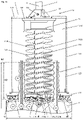
- the at least one conveyor spiral or two conveyor spirals preferably rotated by 180° relative to one another, is provided with a side wall in a lower section, which is preferably selected according to the height of the pile heads to be processed.
- the side wall ensures that the milled material in the lower section cannot escape from the spiral conveyors and from the remaining area of the pile head, which contains the Has reinforcement, can be promoted. Only after the milling material has been conveyed out of this area can it emerge laterally in an upper section of the conveying spiral, which is not provided with a side wall, and be guided out of the milling head via the at least one exit window.
- the central drill When operating the milling head, the central drill penetrates the core of the pile first.
- the central chisels then penetrate the pile core sequentially and in stages in pairs, so that the pile core is machined from the inside out.
- the surface tension of the pile core is broken step by step by arranging the central chisel in a stepped manner. Instead of rupturing the surface of the pile core in one step, the surface tension is broken gradually and thus with reduced force.
- the milling head according to the invention can therefore be operated efficiently with reduced force or reduced drive torques.
- the central chisel and ring chisel are preferably arranged in at least two spirally running rows and are mounted on the underside of the inner ring plate and the outer ring plate, respectively.
- the chisel height of the central chisel preferably increases, as described, linearly or non-linearly sequentially from central chisel to central chisel in the direction of the axis of rotation or in the direction of the central drill radially inwards.
- the invention therefore combines these three essential advantages, which are normally mutually exclusive. With reduced energy consumption, material is broken down faster and more gently. It should be noted that the milling process is promoted on the one hand by the disposal of the milling material according to the invention and on the other hand by the advantageous arrangement of the central chisel and/or ring chisel.
- the central chisels provided on the central milling machine and the ring chisels provided on the ring milling machine preferably consist of a holder that can be welded or mounted in a form-fitting manner and a chiseling element that can be inserted therein and that can be routinely replaced.
- the holders are preferably connected to the associated holders or assembly elements of the ring plates by means of form-fitting connections, for example dovetail connections.
- the ring chisels are preferably dimensioned somewhat larger than the central chisels. Further one of the ring bits can be connected to the inner ring plate as a clearing bit.
- the milling head is made of durable material, especially iron and steel.
- the tool parts that come into contact with the concrete pile are preferably made of hard metal.
- the milling tools include receiving openings are used in the hard metal elements that are used to machine the concrete.
- Plastic parts can be used if they have the desired strength and should give the milling head or parts of it a certain elasticity, for example.
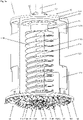
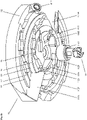
- the ring milling machine 12 comprises an outer ring plate 122, on the underside of which ring bits 121 are mounted in the direction of rotation or inclined thereto.
- the upper side of the outer ring plate 122 is preferably detachably connected to the underside of a mounting cylinder 123, e.g. by means of flange elements and screws or threaded elements, the upper side of which is preferably detachably connected to the coupling plate 133, e.g. by means of flange elements and screws or threaded elements.
- the assembly cylinder 123 has a quarter section through which the view of the central milling machine 11 is uncovered.
- the assembly cylinder 123 has exit windows 1231 through which loosened milling material can be carried away to the outside.
- the assembly cylinder 123 has assembly windows 1232 on the upper side, which allow access to the milling head 1, e.g. in order to release the central milling machine 11.
- the outer ring plate 122 has an outside diameter d122o and an inside diameter d122i.
- the inner ring plate 112 has an outer diameter d112.
- the increase in the mounting height of the ring bit 121 is preferably in a range of 5 mm - 25 mm.
- the increase in mounting height of the first ring bits 1211, 1212, ... is close to 5 mm and the increase in mounting height of the last ring bits ..., 12111, 12112 is close to 25 mm.
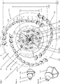
- Figure 5a shows the complete with central chisels 111; radial vanes 118A, 118B; conveyor blades 119A, 119B; clearing tools 1119A, 1119B; and the central drill 114 tipped inner ring plate 112 of Figure 3a in spatial representation.
- a series of central chisels 111 is provided with the associated serial numbers 1111, 1112, ..., 1108. Also shown on the right is a view over impeller blade 119B through transfer opening 1120B.
- the underside of the inner ring plate 112 is provided with annular steps S1, S2, S3, S4, S5, which preferably correspond to the working groups m1.
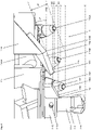
- the blade inclination angle a4 which is approximately 45° in the embodiment shown, is therefore selected in such a way that the milled material can reach the transfer opening 1020B via the conveyor blade 119B and on to the conveyor spiral 113B.
- the conveying blade 119B has an outer wall 119S so that the conveyed milling material cannot escape to the outside.
- the transfer surface 1125B is preferably shaped in such a way that a preferably laminar transition without obstacles results between the conveyor blade 119B at the entrance of the conveyor spiral 113B.
- Figure 6b shows the inner ring plate 112 of FIG Figure 6a without the feed spirals 113A, 113B, the shaft 115 and the feed blade 119B.
- a connection space with a connection surface 1127 is exposed at the lower edge of the transfer surface 1125B or on the underside of the transfer opening 1120B, in which the conveyor blade 119B is fastened. eg screwed and/or welded.
Landscapes
- Engineering & Computer Science (AREA)
- Structural Engineering (AREA)
- Mining & Mineral Resources (AREA)
- General Engineering & Computer Science (AREA)
- Paleontology (AREA)
- Civil Engineering (AREA)
- Life Sciences & Earth Sciences (AREA)
- General Life Sciences & Earth Sciences (AREA)
- Mechanical Engineering (AREA)
- Piles And Underground Anchors (AREA)
- Earth Drilling (AREA)
- Placing Or Removing Of Piles Or Sheet Piles, Or Accessories Thereof (AREA)
- Drilling And Boring (AREA)
Priority Applications (12)
| Application Number | Priority Date | Filing Date | Title |
|---|---|---|---|
| EP21154111.5A EP4036314A1 (fr) | 2021-01-28 | 2021-01-28 | Tête de fraisage destinée à l'usinage de têtes de pieu |
| EP22700499.1A EP4284978B1 (fr) | 2021-01-28 | 2022-01-13 | Tête de fraisage destinée à l'usinage de têtes de pieu |
| KR1020237027714A KR20230134527A (ko) | 2021-01-28 | 2022-01-13 | 말뚝 머리부를 기계 가공하기 위한 밀링 머리부 |
| CN202280012311.2A CN116829788A (zh) | 2021-01-28 | 2022-01-13 | 用于机加工桩头的铣头 |
| CN202411901415.6A CN119465940A (zh) | 2021-01-28 | 2022-01-13 | 用于机加工桩头的铣头 |
| AU2022212344A AU2022212344A1 (en) | 2021-01-28 | 2022-01-13 | Milling head for machining pile heads |
| ES22700499T ES3026151T3 (en) | 2021-01-28 | 2022-01-13 | Milling head for machining pile heads |
| US18/267,703 US12454801B2 (en) | 2021-01-28 | 2022-01-13 | Milling head for machining pile heads |
| JP2023540598A JP2024504280A (ja) | 2021-01-28 | 2022-01-13 | パイルヘッドを機械加工するための切削ヘッド |
| CA3202124A CA3202124A1 (fr) | 2021-01-28 | 2022-01-13 | Tete de fraisage pour l'usinage de tetes de pieu |
| PCT/EP2022/050637 WO2022161782A1 (fr) | 2021-01-28 | 2022-01-13 | Tête de fraisage pour l'usinage de têtes de pieu |
| PL22700499.1T PL4284978T3 (pl) | 2021-01-28 | 2022-01-13 | Głowica frezarska do obróbki głowic pali |
Applications Claiming Priority (1)
| Application Number | Priority Date | Filing Date | Title |
|---|---|---|---|
| EP21154111.5A EP4036314A1 (fr) | 2021-01-28 | 2021-01-28 | Tête de fraisage destinée à l'usinage de têtes de pieu |
Publications (1)
| Publication Number | Publication Date |
|---|---|
| EP4036314A1 true EP4036314A1 (fr) | 2022-08-03 |
Family
ID=74418150
Family Applications (2)
| Application Number | Title | Priority Date | Filing Date |
|---|---|---|---|
| EP21154111.5A Withdrawn EP4036314A1 (fr) | 2021-01-28 | 2021-01-28 | Tête de fraisage destinée à l'usinage de têtes de pieu |
| EP22700499.1A Active EP4284978B1 (fr) | 2021-01-28 | 2022-01-13 | Tête de fraisage destinée à l'usinage de têtes de pieu |
Family Applications After (1)
| Application Number | Title | Priority Date | Filing Date |
|---|---|---|---|
| EP22700499.1A Active EP4284978B1 (fr) | 2021-01-28 | 2022-01-13 | Tête de fraisage destinée à l'usinage de têtes de pieu |
Country Status (10)
| Country | Link |
|---|---|
| US (1) | US12454801B2 (fr) |
| EP (2) | EP4036314A1 (fr) |
| JP (1) | JP2024504280A (fr) |
| KR (1) | KR20230134527A (fr) |
| CN (2) | CN116829788A (fr) |
| AU (1) | AU2022212344A1 (fr) |
| CA (1) | CA3202124A1 (fr) |
| ES (1) | ES3026151T3 (fr) |
| PL (1) | PL4284978T3 (fr) |
| WO (1) | WO2022161782A1 (fr) |
Families Citing this family (1)
| Publication number | Priority date | Publication date | Assignee | Title |
|---|---|---|---|---|
| CN118128043B (zh) * | 2024-04-30 | 2024-07-05 | 山东省建设建工(集团)有限责任公司 | 一种建筑工程用截桩机 |
Citations (4)
| Publication number | Priority date | Publication date | Assignee | Title |
|---|---|---|---|---|
| WO1998042916A1 (fr) * | 1997-03-25 | 1998-10-01 | Ito Co., Ltd. | Machine de decoupage de revetement de route |
| EP1093898A2 (fr) * | 1999-10-18 | 2001-04-25 | Mantovanibenne S.r.l. | Dispositif de recépage de pieux |
| DE10041275A1 (de) * | 2000-08-23 | 2002-03-28 | Klaus Ertmer Maschb Technologi | Frässystem zum Anbau an hydraulische Trägergeräte |
| EP1990167A1 (fr) * | 2007-05-07 | 2008-11-12 | BauRent AG central | Procédé et tête de fraisage destinés au traitement de têtes de pieux |
Family Cites Families (10)
| Publication number | Priority date | Publication date | Assignee | Title |
|---|---|---|---|---|
| JPH0772467B2 (ja) * | 1989-05-31 | 1995-08-02 | 克巳 北中 | 場所打ち杭用のアースオーガおよびそのオーガヘッド |
| JPH076185B2 (ja) * | 1991-03-11 | 1995-01-30 | 壮彦 北中 | 場所打ち杭の杭頭処理方法および装置 |
| JP2005220594A (ja) * | 2004-02-05 | 2005-08-18 | Nippon Beesu Kk | 杭施工方法及びその装置 |
| US20060254818A1 (en) * | 2005-05-12 | 2006-11-16 | Pepple Gregory A | Ice cutter |
| JP4526085B2 (ja) * | 2005-12-19 | 2010-08-18 | 日立住友重機械建機クレーン株式会社 | 地中杭の切断装置 |
| EP1895090B1 (fr) * | 2006-08-23 | 2008-10-15 | BAUER Maschinen GmbH | Procédé et dispositif de réalisation d'un trou de forage dans le sol |
| JP2016142127A (ja) * | 2015-02-03 | 2016-08-08 | 正二 伊藤 | 掘削ヘッド |
| US20190032412A1 (en) * | 2017-06-29 | 2019-01-31 | Daniel Banjo | Auger member |
| CN110513065B (zh) * | 2019-09-30 | 2024-05-10 | 北京三一智造科技有限公司 | 螺旋筒钻 |
| CN111980576A (zh) * | 2020-09-27 | 2020-11-24 | 山河智能装备股份有限公司 | 一种入岩扩孔钻具 |
-
2021
- 2021-01-28 EP EP21154111.5A patent/EP4036314A1/fr not_active Withdrawn
-
2022
- 2022-01-13 CN CN202280012311.2A patent/CN116829788A/zh active Pending
- 2022-01-13 JP JP2023540598A patent/JP2024504280A/ja active Pending
- 2022-01-13 WO PCT/EP2022/050637 patent/WO2022161782A1/fr not_active Ceased
- 2022-01-13 US US18/267,703 patent/US12454801B2/en active Active
- 2022-01-13 KR KR1020237027714A patent/KR20230134527A/ko active Pending
- 2022-01-13 EP EP22700499.1A patent/EP4284978B1/fr active Active
- 2022-01-13 AU AU2022212344A patent/AU2022212344A1/en active Pending
- 2022-01-13 PL PL22700499.1T patent/PL4284978T3/pl unknown
- 2022-01-13 ES ES22700499T patent/ES3026151T3/es active Active
- 2022-01-13 CA CA3202124A patent/CA3202124A1/fr active Pending
- 2022-01-13 CN CN202411901415.6A patent/CN119465940A/zh active Pending
Patent Citations (5)
| Publication number | Priority date | Publication date | Assignee | Title |
|---|---|---|---|---|
| WO1998042916A1 (fr) * | 1997-03-25 | 1998-10-01 | Ito Co., Ltd. | Machine de decoupage de revetement de route |
| EP1093898A2 (fr) * | 1999-10-18 | 2001-04-25 | Mantovanibenne S.r.l. | Dispositif de recépage de pieux |
| DE10041275A1 (de) * | 2000-08-23 | 2002-03-28 | Klaus Ertmer Maschb Technologi | Frässystem zum Anbau an hydraulische Trägergeräte |
| EP1990167A1 (fr) * | 2007-05-07 | 2008-11-12 | BauRent AG central | Procédé et tête de fraisage destinés au traitement de têtes de pieux |
| WO2008135365A1 (fr) | 2007-05-07 | 2008-11-13 | Baurent Ag Central | Tête de fraisage et procédé d'usinage de têtes de pile |
Also Published As
| Publication number | Publication date |
|---|---|
| EP4284978B1 (fr) | 2025-04-02 |
| EP4284978C0 (fr) | 2025-04-02 |
| AU2022212344A1 (en) | 2023-07-20 |
| US20240018735A1 (en) | 2024-01-18 |
| WO2022161782A1 (fr) | 2022-08-04 |
| ES3026151T3 (en) | 2025-06-10 |
| CN119465940A (zh) | 2025-02-18 |
| PL4284978T3 (pl) | 2025-08-04 |
| AU2022212344A9 (en) | 2024-07-11 |
| EP4284978A1 (fr) | 2023-12-06 |
| CA3202124A1 (fr) | 2022-08-04 |
| KR20230134527A (ko) | 2023-09-21 |
| US12454801B2 (en) | 2025-10-28 |
| CN116829788A (zh) | 2023-09-29 |
| JP2024504280A (ja) | 2024-01-31 |
Similar Documents
| Publication | Publication Date | Title |
|---|---|---|
| EP2685007B1 (fr) | Cutting wheel for a slotted wall cutter | |
| EP2739790B1 (fr) | Coupage d'un pieu off-shore | |
| EP3039218B1 (fr) | Tête de forage permettant d'élargir un forage pilote pour produire un trou foré | |
| EP0778100A1 (fr) | Foret héliocoidal de percussion | |
| EP2740882B1 (fr) | Dispositif de forage et procédé de création d'un trou de forage | |
| EP3336301B1 (fr) | Perforatrice rotative et procédé de fabrication d'un alésage | |
| AT507864B1 (de) | Längsschneidkopf für vortriebs- oder gewinnungsmaschinen | |
| EP4284978B1 (fr) | Tête de fraisage destinée à l'usinage de têtes de pieu | |
| JP5641476B2 (ja) | フライスヘッド及びパイルヘッドを機械加工する方法 | |
| EP1640507A1 (fr) | Appareil de forage pour pieu | |
| DE112012001728T5 (de) | Tunnelbohrvorrichtung | |
| DE4109871A1 (de) | Rohrvorpresseinrichtung und rohrvorpressverfahren zum verlegen von rohrleitungen mit nicht-begehbarem innendurchmesser im erdboden | |
| DE3125480A1 (de) | Bohrvorrichtung, insbesondere fuer das herstellen radialer abzweigbohrungen an roehren aus stahl, gusseisen, keramik etc. | |
| RU2841852C1 (ru) | Фрезерная головка для обработки оголовков свай | |
| DE19533281A1 (de) | Verfahren und Vorrichtung zum Vortrieb von Hohlprofilen in den Baugrund | |
| EP3361040B1 (fr) | Outil de traitement de sol et procédé de production d'un trou dans le sol | |
| DE102014117170B4 (de) | Werkzeug zur Bearbeitung eines Pfahls | |
| EP3387209B1 (fr) | Dispositif et procédé de forçage d'une cavité dans une exploitation minière souterraine | |
| DE29622294U1 (de) | Werkzeug zum Ausbohren von in Rohrbündelplatten eingesetzten und verschweißten Rohren eines Rohrbündelwärmetauschers | |
| EP3928928B1 (fr) | Outil de burinage doté d'une section structurée | |
| EP2322727B1 (fr) | Dispositif d'aspiration pour une drague suceuse destinée à collecter et séparer des matériaux dragués tels que de la terre ou des boues, et drague suceuse en étant équipée | |
| AT82656B (de) | Verfahren und Einrichtung zum Bohren von Stollen, Tunnels u. dgl. | |
| DE2722526C3 (de) | Schrämwalze für eine Bergbau-Gewinnungsmaschine | |
| DE3915538A1 (de) | Bohrvorrichtung fuer fels- bzw. hartgestein | |
| EP1760255A1 (fr) | Appareil d'abattage |
Legal Events
| Date | Code | Title | Description |
|---|---|---|---|
| PUAI | Public reference made under article 153(3) epc to a published international application that has entered the european phase |
Free format text: ORIGINAL CODE: 0009012 |
|
| STAA | Information on the status of an ep patent application or granted ep patent |
Free format text: STATUS: THE APPLICATION HAS BEEN PUBLISHED |
|
| AK | Designated contracting states |
Kind code of ref document: A1 Designated state(s): AL AT BE BG CH CY CZ DE DK EE ES FI FR GB GR HR HU IE IS IT LI LT LU LV MC MK MT NL NO PL PT RO RS SE SI SK SM TR |
|
| STAA | Information on the status of an ep patent application or granted ep patent |
Free format text: STATUS: THE APPLICATION IS DEEMED TO BE WITHDRAWN |
|
| 18D | Application deemed to be withdrawn |
Effective date: 20230204 |