EP4037104B1 - Anschlussblock mit einer leiterschiene mit einem seitlichen abschnitt - Google Patents
Anschlussblock mit einer leiterschiene mit einem seitlichen abschnitt Download PDFInfo
- Publication number
- EP4037104B1 EP4037104B1 EP21305104.8A EP21305104A EP4037104B1 EP 4037104 B1 EP4037104 B1 EP 4037104B1 EP 21305104 A EP21305104 A EP 21305104A EP 4037104 B1 EP4037104 B1 EP 4037104B1
- Authority
- EP
- European Patent Office
- Prior art keywords
- terminal block
- cooperating
- leg
- retaining spring
- conductive bar
- Prior art date
- Legal status (The legal status is an assumption and is not a legal conclusion. Google has not performed a legal analysis and makes no representation as to the accuracy of the status listed.)
- Active
Links
Images

Classifications
-
- H—ELECTRICITY
- H01—ELECTRIC ELEMENTS
- H01R—ELECTRICALLY-CONDUCTIVE CONNECTIONS; STRUCTURAL ASSOCIATIONS OF A PLURALITY OF MUTUALLY-INSULATED ELECTRICAL CONNECTING ELEMENTS; COUPLING DEVICES; CURRENT COLLECTORS
- H01R13/00—Details of coupling devices of the kinds covered by groups H01R12/70 or H01R24/00 - H01R33/00
- H01R13/02—Contact members
-
- H—ELECTRICITY
- H01—ELECTRIC ELEMENTS
- H01R—ELECTRICALLY-CONDUCTIVE CONNECTIONS; STRUCTURAL ASSOCIATIONS OF A PLURALITY OF MUTUALLY-INSULATED ELECTRICAL CONNECTING ELEMENTS; COUPLING DEVICES; CURRENT COLLECTORS
- H01R9/00—Structural associations of a plurality of mutually-insulated electrical connecting elements, e.g. terminal strips or terminal blocks; Terminals or binding posts mounted upon a base or in a case; Bases therefor
- H01R9/22—Bases, e.g. strip, block, panel
- H01R9/24—Terminal blocks
- H01R9/26—Clip-on terminal blocks for side-by-side rail- or strip-mounting
-
- H—ELECTRICITY
- H01—ELECTRIC ELEMENTS
- H01R—ELECTRICALLY-CONDUCTIVE CONNECTIONS; STRUCTURAL ASSOCIATIONS OF A PLURALITY OF MUTUALLY-INSULATED ELECTRICAL CONNECTING ELEMENTS; COUPLING DEVICES; CURRENT COLLECTORS
- H01R9/00—Structural associations of a plurality of mutually-insulated electrical connecting elements, e.g. terminal strips or terminal blocks; Terminals or binding posts mounted upon a base or in a case; Bases therefor
- H01R9/22—Bases, e.g. strip, block, panel
- H01R9/24—Terminal blocks
- H01R9/26—Clip-on terminal blocks for side-by-side rail- or strip-mounting
- H01R9/2608—Fastening means for mounting on support rail or strip
-
- H—ELECTRICITY
- H01—ELECTRIC ELEMENTS
- H01R—ELECTRICALLY-CONDUCTIVE CONNECTIONS; STRUCTURAL ASSOCIATIONS OF A PLURALITY OF MUTUALLY-INSULATED ELECTRICAL CONNECTING ELEMENTS; COUPLING DEVICES; CURRENT COLLECTORS
- H01R13/00—Details of coupling devices of the kinds covered by groups H01R12/70 or H01R24/00 - H01R33/00
- H01R13/40—Securing contact members in or to a base or case; Insulating of contact members
-
- H—ELECTRICITY
- H01—ELECTRIC ELEMENTS
- H01R—ELECTRICALLY-CONDUCTIVE CONNECTIONS; STRUCTURAL ASSOCIATIONS OF A PLURALITY OF MUTUALLY-INSULATED ELECTRICAL CONNECTING ELEMENTS; COUPLING DEVICES; CURRENT COLLECTORS
- H01R4/00—Electrically-conductive connections between two or more conductive members in direct contact, i.e. touching one another; Means for effecting or maintaining such contact; Electrically-conductive connections having two or more spaced connecting locations for conductors and using contact members penetrating insulation
- H01R4/28—Clamped connections, spring connections
- H01R4/48—Clamped connections, spring connections utilising a spring, clip, or other resilient member
- H01R4/4809—Clamped connections, spring connections utilising a spring, clip, or other resilient member using a leaf spring to bias the conductor toward the busbar
- H01R4/4846—Busbar details
-
- H—ELECTRICITY
- H01—ELECTRIC ELEMENTS
- H01R—ELECTRICALLY-CONDUCTIVE CONNECTIONS; STRUCTURAL ASSOCIATIONS OF A PLURALITY OF MUTUALLY-INSULATED ELECTRICAL CONNECTING ELEMENTS; COUPLING DEVICES; CURRENT COLLECTORS
- H01R4/00—Electrically-conductive connections between two or more conductive members in direct contact, i.e. touching one another; Means for effecting or maintaining such contact; Electrically-conductive connections having two or more spaced connecting locations for conductors and using contact members penetrating insulation
- H01R4/28—Clamped connections, spring connections
- H01R4/48—Clamped connections, spring connections utilising a spring, clip, or other resilient member
- H01R4/4809—Clamped connections, spring connections utilising a spring, clip, or other resilient member using a leaf spring to bias the conductor toward the busbar
- H01R4/4846—Busbar details
- H01R4/485—Single busbar common to multiple springs
-
- H—ELECTRICITY
- H01—ELECTRIC ELEMENTS
- H01R—ELECTRICALLY-CONDUCTIVE CONNECTIONS; STRUCTURAL ASSOCIATIONS OF A PLURALITY OF MUTUALLY-INSULATED ELECTRICAL CONNECTING ELEMENTS; COUPLING DEVICES; CURRENT COLLECTORS
- H01R11/00—Individual connecting elements providing two or more spaced connecting locations for conductive members which are, or may be, thereby interconnected, e.g. end pieces for wires or cables supported by the wire or cable and having means for facilitating electrical connection to some other wire, terminal, or conductive member, blocks of binding posts
- H01R11/03—Individual connecting elements providing two or more spaced connecting locations for conductive members which are, or may be, thereby interconnected, e.g. end pieces for wires or cables supported by the wire or cable and having means for facilitating electrical connection to some other wire, terminal, or conductive member, blocks of binding posts characterised by the relationship between the connecting locations
- H01R11/09—Individual connecting elements providing two or more spaced connecting locations for conductive members which are, or may be, thereby interconnected, e.g. end pieces for wires or cables supported by the wire or cable and having means for facilitating electrical connection to some other wire, terminal, or conductive member, blocks of binding posts characterised by the relationship between the connecting locations the connecting locations being identical
-
- H—ELECTRICITY
- H01—ELECTRIC ELEMENTS
- H01R—ELECTRICALLY-CONDUCTIVE CONNECTIONS; STRUCTURAL ASSOCIATIONS OF A PLURALITY OF MUTUALLY-INSULATED ELECTRICAL CONNECTING ELEMENTS; COUPLING DEVICES; CURRENT COLLECTORS
- H01R2101/00—One pole
-
- H—ELECTRICITY
- H01—ELECTRIC ELEMENTS
- H01R—ELECTRICALLY-CONDUCTIVE CONNECTIONS; STRUCTURAL ASSOCIATIONS OF A PLURALITY OF MUTUALLY-INSULATED ELECTRICAL CONNECTING ELEMENTS; COUPLING DEVICES; CURRENT COLLECTORS
- H01R4/00—Electrically-conductive connections between two or more conductive members in direct contact, i.e. touching one another; Means for effecting or maintaining such contact; Electrically-conductive connections having two or more spaced connecting locations for conductors and using contact members penetrating insulation
- H01R4/28—Clamped connections, spring connections
- H01R4/48—Clamped connections, spring connections utilising a spring, clip, or other resilient member
- H01R4/4809—Clamped connections, spring connections utilising a spring, clip, or other resilient member using a leaf spring to bias the conductor toward the busbar
- H01R4/48185—Clamped connections, spring connections utilising a spring, clip, or other resilient member using a leaf spring to bias the conductor toward the busbar adapted for axial insertion of a wire end
- H01R4/4819—Clamped connections, spring connections utilising a spring, clip, or other resilient member using a leaf spring to bias the conductor toward the busbar adapted for axial insertion of a wire end the spring shape allowing insertion of the conductor end when the spring is unbiased
- H01R4/4821—Single-blade spring
-
- H—ELECTRICITY
- H01—ELECTRIC ELEMENTS
- H01R—ELECTRICALLY-CONDUCTIVE CONNECTIONS; STRUCTURAL ASSOCIATIONS OF A PLURALITY OF MUTUALLY-INSULATED ELECTRICAL CONNECTING ELEMENTS; COUPLING DEVICES; CURRENT COLLECTORS
- H01R4/00—Electrically-conductive connections between two or more conductive members in direct contact, i.e. touching one another; Means for effecting or maintaining such contact; Electrically-conductive connections having two or more spaced connecting locations for conductors and using contact members penetrating insulation
- H01R4/28—Clamped connections, spring connections
- H01R4/48—Clamped connections, spring connections utilising a spring, clip, or other resilient member
- H01R4/4809—Clamped connections, spring connections utilising a spring, clip, or other resilient member using a leaf spring to bias the conductor toward the busbar
- H01R4/484—Spring housing details
- H01R4/4842—Spring housing details the spring housing being provided with a single opening for insertion of a spring-activating tool
-
- H—ELECTRICITY
- H01—ELECTRIC ELEMENTS
- H01R—ELECTRICALLY-CONDUCTIVE CONNECTIONS; STRUCTURAL ASSOCIATIONS OF A PLURALITY OF MUTUALLY-INSULATED ELECTRICAL CONNECTING ELEMENTS; COUPLING DEVICES; CURRENT COLLECTORS
- H01R43/00—Apparatus or processes specially adapted for manufacturing, assembling, maintaining, or repairing of line connectors or current collectors or for joining electric conductors
- H01R43/16—Apparatus or processes specially adapted for manufacturing, assembling, maintaining, or repairing of line connectors or current collectors or for joining electric conductors for manufacturing contact members, e.g. by punching and by bending
Definitions
- the present invention concerns a terminal block comprising a conductive bar with a lateral portion.
- the terminal block comprises a plurality of plugs with a releasable mechanisms to maintain an electrical contact between each conductor and the conductive bar.
- CN209001163 U describes a terminal block according to the preamble of claim 1.
- Such a release mechanism usually comprises a retaining spring. This construction enables to constraint the conductor to build an efficient electrical contact.
- an insulating casing of the terminal can have dedicated walls, the conductive bar can have a specific form or additional accessories can be used.
- the present invention aims to solve all or some of the disadvantages mentioned above.
- the present invention relates to a terminal block comprising an insulating casing, a conductive bar and a retaining spring, the insulating casing extending according to a main plane and presenting a lateral recess arranged for an insertion of the conductive bar and the retaining spring transversally to the main plane into a mounted position, the conductive bar presenting in mounted position a base portion extending according to a middle plane transversal to the main plane and a lateral portion attached to the base portion and extending parallel to the main plane, the conductive bar further comprising a support leg attached to the base portion and configured to cooperate with a support part of the retaining spring and a cooperating leg attached to the base portion and configured to cooperate with a conductor inserted in a plug of the terminal block when the conductor is maintained by the retaining spring, the support leg and cooperating leg being transverse to the middle plane and extending in opposite directions transversally to the middle plane, the lateral portion and the cooperating leg extending according to the same direction transversally
- the support leg, the cooperating leg and the lateral portion are each attached to the base portion and extending transversally with respect to the base portion.
- the support leg is extending from the base portion according to a direction and both the cooperating leg and the lateral portion are extending from the base portion according to the opposite direction.
- This construction enables to laterally maintain the plugged conductor and also to exert a maintaining force on the conductor in proximity to a junction between the base portion and the lateral portion with the retaining spring.
- This geometry is especially efficient when a multi-stranded conductor is used but also suits for rigid pushed conductors. With a multi-stranded conductor, it improves the quality of the electrical contact as there is a limited risk of strand deviation during insertion of the conductor.
- the lateral recess of the insulating casing presents a bottom surface; the retaining spring, the support leg and the cooperating leg being located between the bottom surface and the lateral portion transversally to the main plane.
- the conductor When inserted, the conductor is located between the lateral portion and the bottom surface transversally to the main plane. The conductor is then guided on one side by the conductive bar and on the other side by the insulating casing.
- the conductive bar presents an L-shaped profile constituted by the base portion and the lateral portion. This provision enables to guide and maintain the plugged conductor laterally with a conductive bar constituted by a limited amount of conductive material.
- the plug has an inserting hole made in the insulating casing, said inserting hole extending transversally to the middle plane and opening on the lateral recess.
- the conductor is maintained transversally to the main plane by the insulating casing on both sides in the inserting hole and then on one side by the lateral portion and on the other side by the bottom surface in the lateral recess.
- the retaining spring is a leaf spring provided with two strips that are symmetrical with respect to a central plane of the retaining spring without any constraints applied on the retaining spring.
- the central plane in mounted position, is transversal to the main plane and to the middle plane.
- the central plane is inclined with respect to the inserting hole. More particularly, the central plane is perpendicular to the main plane and inclined with respect to the middle plane, the inclination being greater than 45°.
- the retaining spring to exert a pressure on the conductor in an inclined way with respect to the middle plane.
- the support leg and the cooperating leg are located on both sides of the middle plane, this means that the retaining spring also comprises parts on the two sides of the middle plane.
- the assembly constituted by the conductive bar and the retaining spring is then compact transversally to the middle plane.
- the insulating casing is provided with an actuating orifice of made in the insulating casing, said actuating orifice extending transversally to the middle plane and opening on the lateral recess.
- the actuating orifice being oriented toward a movable part of the retaining spring.
- the actuating orifice is configured to enable a tool such as a screwdriver to displace said moving part.
- the moving part is configured to exert a constraint on the conductor in the absence of actuation to maintain the conductor electrically connected on the cooperating leg.
- each strip of the retaining spring extend according to a corresponding direction and presents to undulations, a first undulation opposed to the central plane and designed to be in front of the actuating orifice and a second undulation toward the central plane to confer an ending part of the retaining spring an inclined orientation with respect to the central plane.
- the first undulation offers a better grip for the tool to actuate the retaining spring.
- the second undulation enables to orient the ending part of the retaining spring away from the central plane. It enables a better grip on the support leg and on the conductor.
- the lateral recess is a lateral blind slot in the thickness of the terminal block, the lateral recess comprising an insert for receiving the retaining spring and the conductive bar within the thickness of the terminal block.
- the lateral blind slot enables an easy insert of the retaining spring and the conductive bar.
- the thickness of the terminal block is defined as being the dimension of the terminal block transversally to the main plane.
- the conductive bar and the retaining spring are contained within the thickness dimension of the terminal block.
- the support leg and the cooperating leg are folded cut-outs of the conductive bar, said folded cut-outs engendering a passage through the base portion transversally to the middle plane.
- the support leg has a lower blocking element arranged to cooperate with a support extremity of the retaining spring to prevent the displacement of said support extremity in a lower direction opposed to the base portion transversally the middle plane.
- the lower blocking element defines a fixed place for the support extremity of the retaining spring. During the insertion of the conductor in the plug, the support extremity stays in place transversally to the middle plane.
- the lower blocking element is a placement corner engendered by a bending made in the support leg.
- the cooperating leg has a higher blocking element arranged to cooperate with a cooperating extremity of the retaining spring to prevent the displacement of said cooperating extremity in a higher direction opposed to the base portion transversally the middle plane.
- the higher blocking element defines a fixed place for the cooperating extremity of the retaining spring. In the absence of the conductor in the plug, the cooperating extremity stays in place transversally to the middle plane. This means that in the absence of the conductor the support extremity and the cooperating extremity are maintained in place transversally to the middle plane.
- the higher blocking element is a placement corner engendered by a bending made in the cooperating leg.
- the cooperating leg comprises a tilted end and a linking part that connects the tilted end to the base portion, the tilted end and the linking part engendering a cooperating protrusion for cooperating with the conductor.
- the cooperating protrusion provides a better electrical contact between the conductor and the support part.
- the higher blocking element is located on the linking part.
- the conductive bar is constituted by a conductive sheet plate that is folded according to a main axis to form the lateral portion and the base portion, the support leg and the cooperating leg being folded parts according to two parallel axis that are transverse to the main axis.
- the construction of the conductive bar is simple as there are a few folding steps. In the same time the conductive bar is rigid enough for its use.
- the conductive sheet plate presents an overall rectangular form, the lateral portion being a side strip and the base portion, support leg and cooperating leg constituting the other strip.
- the support leg and the cooperating leg are contiguous parts of said other strip.
- the side strip presents at least one groove along its length. This confers rigidity to the lateral portion.
- the terminal block comprises a clipping system for installing conductive bar in mounted position.
- the conductive bar comprising a first part of the clipping system and the insulating casing comprises a second part of the clipping system.
- the conductive bar comprises a plurality of associated support legs and cooperating legs for a plurality of corresponding plugs of the terminal block.
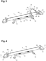
- a terminal block 1 comprises an insulating casing 3, a conductive bar 5 and a retaining spring 7.
- the insulating casing 3 extends according to a main plane 9 and presents a lateral recess 11 arranged for an insertion of the conductive bar 5 and the retaining spring 7 transversally to the main plane 9 into a mounted position.
- the conductive bar 5 presents in mounted position a base portion 13 extending according to a middle plane 15 transversal to the main plane 9 and a lateral portion 17 attached to the base portion 13 and extending parallel to the main plane 9.
- the conductive bar 5 further comprises a support leg 19 attached to the base portion 13 and configured to cooperate with a support part 21 of the retaining spring 7 and a cooperating leg 23 attached to the base portion 13 and configured to cooperate with a conductor 25 inserted in a plug 27 of the terminal block 1 when the conductor 25 is maintained by the retaining spring 7.
- the support leg 19 and the cooperating leg 23 are transverse to the middle plane 15 and extending in opposite directions transversally to the middle plane 15, the lateral portion 17 and the cooperating leg 23 extending according to the same direction transversally to the middle plane 15.
- the support leg 19, the cooperating leg 23 and the lateral portion 17 are each attached to the base portion 13 and extending transversally with respect to the base portion 13.
- the support leg 19 is extending from the base portion 13 according to a direction and both the cooperating leg 23 and the lateral portion 17 are extending from the base portion 13 according to the opposite direction.
- the lateral recess 11 of the insulating casing 3 presents a bottom surface 29.
- the retaining spring 7, the support leg 19 and the cooperating leg 23 are located between the bottom surface 29 and the lateral portion 17 transversally to the main plane 9.
- the conductor 25 When inserted, the conductor 25 is located between the lateral portion 17 and the bottom surface 29 transversally to the main plane 9. The conductor 25 is then guided on one side by the conductive bar 5 and on the other side by the insulating casing 3.
- the conductive bar 5 presents an L-shaped profile constituted by the base portion 13 and the lateral portion 17.
- the plug 27 has an inserting hole 31 made in the insulating casing 3, said inserting hole 31 extending transversally to the middle plane 15 and opening on the lateral recess 11.
- the conductor 25 is maintained transversally to the main plane 9 by the insulating casing 3 on both sides in the inserting hole 31 and then on one side by the lateral portion 17 and on the other side by the bottom surface 31 in the lateral recess 11.
- the retaining spring 7 is a leaf spring provided with two strips 33 that are symmetrical with respect to a central plane 35 of the retaining spring 7 without any constraints applied on the retaining spring 7.
- the central plane 35 In mounted position, the central plane 35 is transversal to the main plane 9 and to the middle plane 15. In addition, the central plane 35 is inclined with respect to the inserting hole 31. More particularly, the central plane 35 is perpendicular to the main plane 9 and inclined with respect to the middle plane 15, the inclination being greater than 45°.
- the insulating casing 3 is provided with an actuating orifice 37 of made in the insulating casing 3, said actuating orifice 37 extending transversally to the middle plane 15 and opening on the lateral recess 11.
- the actuating orifice 37 is oriented toward a movable part 39 of the retaining spring 7.
- the actuating orifice 37 is configured to enable a tool such as a screwdriver 41 to displace said moving part 39.
- the moving part 39 is configured to exert a constraint on the conductor 25 in the absence of actuation to maintain the conductor 25 electrically connected on the cooperating leg 23.
- Each strip 33 of the retaining spring extend according to a corresponding direction and presents two undulations, a first undulation 43 opposed to the central plane 35 and designed to be in front of the actuating orifice 37 and a second undulation 45 toward the central plane 35 to confer an ending part 47 of the retaining spring 7 an inclined orientation with respect to the central plane 35.
- the lateral recess 11 is a lateral blind slot in the thickness 49 of the terminal block 1, the lateral recess 11 comprising an insert for receiving the retaining spring 7 and the conductive bar 5 within the thickness 49 of the terminal block 1.
- the thickness 49 of the terminal block 1 is defined as being the dimension of the terminal block 1 transversally to the main plane 9.
- the conductive bar 5 and the retaining spring 7 are contained within the thickness dimension of the terminal block 1.
- the support leg 19 and the cooperating leg 23 are folded cut-outs of the conductive bar 5, said folded cut-outs engendering a passage 51 through the base portion 13 transversally to the middle plane 15.
- the support leg 19 has a lower blocking element 53 arranged to cooperate with a support extremity 55 of the retaining spring 7 to prevent the displacement of said support extremity 55 in a lower direction 57 opposed to the base portion 13 transversally the middle plane 15.
- the lower blocking element 53 defines a fixed place for the support extremity 55 of the retaining spring 7. During the insertion of the conductor 25 in the plug 27, the support extremity 55 stays in place transversally to the middle plane 15.
- the lower blocking element 53 is a placement corner engendered by a bending made in the support leg 19.
- the cooperating leg 23 has a higher blocking element 59 arranged to cooperate with a cooperating extremity 61 of the retaining spring 7 to prevent the displacement of said cooperating extremity 61 in a higher direction 63 opposed to the base portion 13 transversally the middle plane 15.
- the higher blocking element 59 defines a fixed place for the cooperating extremity 61 of the retaining spring 7. In the absence of the conductor 25 in the plug 27, the cooperating extremity 61 stays in place transversally to the middle plane 15. This means that, in the absence of the conductor 25, the support extremity 55 and the cooperating extremity 61 are maintained in place transversally to the middle plane 15.
- the higher blocking element 59 is a placement corner engendered by a bending made in the cooperating leg 23.
- the cooperating leg 23 comprises a tilted end 65 and a linking part 67 that connects the tilted end 65 to the base portion 13, the tilted end 65 and the linking part 67 engendering a cooperating protrusion 69 for cooperating with the conductor 25.
- the higher blocking element 63 is located on the linking part 67.
- the conductive bar 5 is constituted by a conductive sheet plate that is folded according to a main axis 71 to form the lateral portion 17 and the base portion 13, the support leg 19 and the cooperating leg 23 being folded parts according to two parallel axis 73 that are transverse to the main axis 71.
- the conductive sheet plate presents an overall rectangular form, the lateral portion 17 being a side strip and the base portion 13, support leg 19 and cooperating leg 23 constituting the other strip.
- the support leg 19 and the cooperating leg 23 are contiguous parts of said other strip.
- the side strip presents at least a groove 75 along its length which confers rigidity to the lateral portion 17.
- the terminal block 1 comprises a clipping system 77 for installing conductive bar 5 in mounted position.
- the conductive bar 5 comprises a first part of the clipping system 77 and the insulating casing 3 comprises a second part of the clipping system 77.
- the construction of the terminal block 1 enables to laterally maintain the plugged conductor(s) 25 and also to exert a maintaining force on the conductor(s) 25 in proximity to a junction between the base portion 13 and the lateral portion 17 with the retaining spring 7.
- This geometry is especially efficient when a multi-stranded conductor 25 is used but also suits for rigid push-in conductors 25. With a multi-stranded conductor 25, it improves the quality of the electrical contact as there is a limited risk of strand deviations during insertion of the conductor 25.
- the plugged conductor 25 is guided and maintained laterally with a conductive bar 5 constituted by a limited amount of conductive material.
- the construction of the conductive bar 5 is simple as there are a few folding steps. In the same time the conductive bar 5 is rigid enough for its use.
Landscapes
- Connections Arranged To Contact A Plurality Of Conductors (AREA)
Claims (13)
- Anschlussblock (1), der ein Isoliergehäuse (3), eine leitfähige Schiene (5) und eine Haltefeder (7) umfasst, wobei sich das Isoliergehäuse (3) entlang einer Hauptebene (9) erstreckt und eine seitliche Aussparung (11) aufweist, die für ein Einsetzen der leitfähigen Schiene (5) und der Haltefeder (7) quer zur Hauptebene (9) in eine montierte Position eingerichtet ist, wobei die leitfähige Schiene (5) in montierter Position einen Basisabschnitt (13) aufweist, der sich entlang einer Mittelebene (15) quer zur Hauptebene (9) erstreckt; wobei der Anschlussblock dadurch gekennzeichnet ist, dass die leitfähige Schiene weiter einen seitlichen Abschnitt (17) aufweist, der am Basisabschnitt (13) angebracht ist und sich parallel zur Hauptebene (9) erstreckt, wobei die leitfähige Schiene (5) weiter einen Stützfuß (19), der am Basisabschnitt (13) angebracht und so konfiguriert ist, dass er mit einem Stützteil (21) der Haltefeder (7) zusammenwirkt, und einen zusammenwirkenden Fuß (23) umfasst, der am Basisabschnitt (13) angebracht und so konfiguriert ist, dass er mit einem Leiter (25) zusammenwirkt, der in einen Stecker (27) des Anschlussblocks (1) eingesetzt ist, wenn der Leiter (25) durch die Haltefeder (7) gehalten wird, wobei der Stützfuß (19) und der zusammenwirkende Fuß (23) quer zur Mittelebene (15) verlaufen und sich in entgegengesetzten Richtungen quer zur Mittelebene (15) erstrecken, wobei der seitliche Abschnitt (17) und der zusammenwirkende Fuß (23) sich entlang derselben Richtung quer zur Mittelebene (15) erstrecken.
- Anschlussblock (1) nach Anspruch 1, wobei die seitliche Aussparung (11) des Isoliergehäuses (3) eine Bodenfläche (29) aufweist; wobei die Haltefeder (7), der Stützfuß (19) und der zusammenwirkende Fuß (23) zwischen der Bodenfläche (29) und dem seitlichen Abschnitt (17) quer zur Hauptebene (9) liegen.
- Anschlussblock (1) nach einem der Ansprüche 1 oder 2, wobei der Stecker (27) ein Einsetzloch (31) aufweist, das im Isoliergehäuse (3) ausgeführt ist, wobei sich das Einsetzloch (31) quer zur Mittelebene (15) erstreckt und an der seitlichen Aussparung (11) öffnet.
- Anschlussblock (1) nach einem der Ansprüche 1 bis 3, wobei die Haltefeder (7) eine Blattfeder ist, die mit zwei Streifen (33) versehen ist, die in Bezug auf eine Mittelebene (35) der Haltefeder (7) symmetrisch sind, wenn keine Spannungen an der Haltefeder (7) anliegen.
- Anschlussblock (1) nach einem der Ansprüche 1 bis 4, wobei die seitliche Aussparung (11) ein seitlicher Blindschlitz in der Dicke (49) des Anschlussblocks (1) ist, wobei die seitliche Aussparung (11) einen Einsatz zum Aufnehmen der Haltefeder (7) und der leitfähigen Schiene (5) innerhalb der Dicke (49) des Anschlussblocks (1) umfasst.
- Anschlussblock (1) nach einem der Ansprüche 1 bis 5, wobei der Stützfuß (19) und der zusammenwirkende Fuß (23) gefaltete Ausschnitte der leitfähigen Schiene (5) sind, wobei die gefalteten Ausschnitte einen Durchgang (51) durch den Basisabschnitt (13) quer zur Mittelebene (15) erzeugen.
- Anschlussblock (1) nach Anspruch 6, wobei der Stützfuß (19) ein unteres Sperrelement (53) aufweist, das so eingerichtet ist, dass es mit einem Stützende (55) der Haltefeder (7) zusammenwirkt, um die Verlagerung des Stützendes (55) in eine untere Richtung (57), dem Basisabschnitt (13) entgegengesetzt, quer zur Mittelebene (15) zu verhindern.
- Anschlussblock (1) nach Anspruch 7, wobei das untere Sperrelement (53) eine Platzierungsecke ist, die durch eine im Stützfuß (19) ausgeführte Biegung erzeugt wird.
- Anschlussblock (1) nach einem der Ansprüche 6 bis 8, wobei der zusammenwirkende Fuß (23) ein höheres Sperrelement (59) aufweist, das so eingerichtet ist, dass es mit einem zusammenwirkenden Ende (61) der Haltefeder (7) zusammenwirkt, um die Verlagerung des zusammenwirkenden Endes (61) in eine höhere Richtung (63), dem Basisabschnitt (13) entgegengesetzt, quer zur Mittelebene (15) zu verhindern.
- Anschlussblock (1) nach Anspruch 9, wobei das höhere Sperrelement (59) eine Platzierungsecke ist, die durch eine in dem zusammenwirkenden Fuß (23) ausgeführte Biegung erzeugt wird.
- Anschlussblock (1) nach einem der Ansprüche 9 oder 10, wobei der zusammenwirkende Fuß (23) ein geneigtes Ende (65) und einen Verbindungsteil (67) umfasst, der das geneigte Ende (65) mit dem Basisabschnitt (13) verbindet, wobei das geneigte Ende (65) und der Verbindungsteil (67) einen zusammenwirkenden Vorsprung (69) zum Zusammenwirken mit dem Leiter (25) erzeugen.
- Anschlussblock (1) nach einem der Ansprüche 1 bis 11, wobei die leitfähige Schiene (5) aus einer leitfähigen Blechplatte besteht, die entlang einer Hauptachse (71) gefaltet ist, um den seitlichen Abschnitt (17) und den Basisabschnitt (13) zu bilden, wobei der Stützfuß (19) und der zusammenwirkende Fuß (23) gefaltete Teile entlang zweier paralleler Achsen (73) sind, die quer zur Hauptachse (71) verlaufen.
- Anschlussblock (1) nach einem der Ansprüche 1 bis 12, wobei die leitfähige Schiene (5) eine Vielzahl von zugehörigen Stützfüßen (19) und zusammenwirkenden Füßen (23) für eine Vielzahl von entsprechenden Steckern (27) des Anschlussblocks (1) umfasst.
Priority Applications (3)
| Application Number | Priority Date | Filing Date | Title |
|---|---|---|---|
| EP21305104.8A EP4037104B1 (de) | 2021-01-27 | 2021-01-27 | Anschlussblock mit einer leiterschiene mit einem seitlichen abschnitt |
| CN202210077798.4A CN114824864B (zh) | 2021-01-27 | 2022-01-24 | 包括具有侧向部分的导电条的端子块 |
| US17/585,151 US12034265B2 (en) | 2021-01-27 | 2022-01-26 | Terminal block |
Applications Claiming Priority (1)
| Application Number | Priority Date | Filing Date | Title |
|---|---|---|---|
| EP21305104.8A EP4037104B1 (de) | 2021-01-27 | 2021-01-27 | Anschlussblock mit einer leiterschiene mit einem seitlichen abschnitt |
Publications (2)
| Publication Number | Publication Date |
|---|---|
| EP4037104A1 EP4037104A1 (de) | 2022-08-03 |
| EP4037104B1 true EP4037104B1 (de) | 2024-11-20 |
Family
ID=74625941
Family Applications (1)
| Application Number | Title | Priority Date | Filing Date |
|---|---|---|---|
| EP21305104.8A Active EP4037104B1 (de) | 2021-01-27 | 2021-01-27 | Anschlussblock mit einer leiterschiene mit einem seitlichen abschnitt |
Country Status (3)
| Country | Link |
|---|---|
| US (1) | US12034265B2 (de) |
| EP (1) | EP4037104B1 (de) |
| CN (1) | CN114824864B (de) |
Family Cites Families (23)
| Publication number | Priority date | Publication date | Assignee | Title |
|---|---|---|---|---|
| KR100480196B1 (ko) * | 2000-08-04 | 2005-04-06 | 오므론 가부시키가이샤 | 전선 접속기구 |
| DE20313041U1 (de) * | 2003-08-23 | 2003-10-23 | Phoenix Contact GmbH & Co. KG, 32825 Blomberg | Klemmanordnung für eine Federkraftklemme |
| DE202005005369U1 (de) | 2004-11-13 | 2006-03-16 | Weidmüller Interface GmbH & Co. KG | Anschlußvorrichtung zum Direktsteckanschluß von Leiterenden und elektrisches Gerät mit einer derartigen Anschlußvorrichtung |
| DE102007036295B4 (de) * | 2007-07-31 | 2009-10-08 | Phoenix Contact Gmbh & Co. Kg | Steckbare Printklemme |
| DE102011012021A1 (de) | 2011-02-22 | 2012-08-23 | Phoenix Contact Gmbh & Co. Kg | Metallteil für eine elektronische Anschlussvorrichtung |
| US8851920B2 (en) * | 2011-10-12 | 2014-10-07 | Switchlab Inc. | Plug-in wire connection terminal structure |
| DE102012009286A1 (de) | 2012-05-11 | 2013-11-14 | Phoenix Contact Gmbh & Co. Kg | Elektrische Reihenklemme |
| DE202012103314U1 (de) | 2012-08-30 | 2013-12-02 | Weidmüller Interface GmbH & Co. KG | Anschlussvorrichtung für einen Leiter |
| US20140113502A1 (en) | 2012-09-28 | 2014-04-24 | Phoenix Contact Development & Manufacturing, Inc. | Connector Block with Spring-Loaded Electrical Terminal Assemblies |
| DE102013108952A1 (de) | 2013-08-20 | 2015-03-12 | Phoenix Contact Gmbh & Co. Kg | Betätigungselement und Anschlussklemme |
| CN105556751B (zh) | 2013-09-16 | 2018-02-16 | 威德米勒界面有限公司及两合公司 | 用于直插式端子的端子笼 |
| DE102013110481A1 (de) * | 2013-09-23 | 2015-03-26 | Phoenix Contact Gmbh & Co. Kg | Elektrische Anschlussklemme |
| DE102015113512B3 (de) * | 2015-08-17 | 2016-12-22 | Phoenix Contact Gmbh & Co. Kg | Klemmanordnung und Federkraftklemme |
| DE102015114938A1 (de) | 2015-09-07 | 2017-03-09 | Eaton Electrical Ip Gmbh & Co. Kg | Kontaktierungsvorrichtung zum Kontaktieren eines elektrischen Leiters und eines elektrischen Steckers an eine elektrische Leiterbahn |
| DE202015105022U1 (de) | 2015-09-22 | 2016-12-23 | Weidmüller Interface GmbH & Co. KG | Anschlussvorrichtung für Leiter |
| US10374332B2 (en) | 2015-10-27 | 2019-08-06 | Tyco Electronics Services Gmbh | Device for holding and bringing into electrical contact conductors |
| WO2018221312A1 (ja) * | 2017-05-29 | 2018-12-06 | Idec株式会社 | 接続機器 |
| DE202017006317U1 (de) * | 2017-12-08 | 2019-03-27 | Wago Verwaltungsgesellschaft Mbh | Federkraftklemmanschluss für einen elektrischen Leiter |
| EP3766132B1 (de) | 2018-03-13 | 2024-10-30 | Weidmüller Interface GmbH & Co. KG | Federkraftklemme für leiter |
| TWI666836B (zh) | 2018-03-16 | 2019-07-21 | 進聯工業股份有限公司 | 電性接線裝置之導電組件結構 |
| TWI659581B (zh) | 2018-03-16 | 2019-05-11 | 進聯工業股份有限公司 | Conductive component structure of wire coupling device |
| CN209001163U (zh) * | 2018-12-10 | 2019-06-18 | 上海友邦电气(集团)股份有限公司 | 直通式智能连接器 |
| DE102019111453A1 (de) | 2019-05-03 | 2020-11-05 | Weidmüller Interface GmbH & Co. KG | Federkraftklemme für Leiter |
-
2021
- 2021-01-27 EP EP21305104.8A patent/EP4037104B1/de active Active
-
2022
- 2022-01-24 CN CN202210077798.4A patent/CN114824864B/zh active Active
- 2022-01-26 US US17/585,151 patent/US12034265B2/en active Active
Also Published As
| Publication number | Publication date |
|---|---|
| CN114824864B (zh) | 2025-01-03 |
| US20220239021A1 (en) | 2022-07-28 |
| US12034265B2 (en) | 2024-07-09 |
| CN114824864A (zh) | 2022-07-29 |
| EP4037104A1 (de) | 2022-08-03 |
Similar Documents
| Publication | Publication Date | Title |
|---|---|---|
| US10014596B2 (en) | Conductor terminal | |
| CN105659436B (zh) | 弹簧接线端子和插接连接器 | |
| EP1635425B1 (de) | Verbindungsanschluss | |
| EP1291976B1 (de) | Reihenklemme mit Schneidkontakten und Anschlussvorrichtung | |
| CN103633462B (zh) | 连接器 | |
| US7118404B2 (en) | Insulation cutting and displacing contact element | |
| JPS648901B2 (de) | ||
| US7399190B2 (en) | Connecting device | |
| CN111613931B (zh) | 用于插塞连接器的保持框架 | |
| EP4071934A1 (de) | Klemmenblock für die aufnahme von nicht-geklebten kabelenden konfiguriert | |
| US20020037671A1 (en) | Terminal block with disconnect contact and terminal arrangement | |
| KR20150119856A (ko) | 스프링 부하형 연결 단자 및 전도체 연결 단자 | |
| EP3662539B1 (de) | Elektrischer steckverbinder | |
| US20180351271A1 (en) | Plug-in contact | |
| US4715824A (en) | Connector for interconnecting cable to a printed circuit board | |
| JPH09219224A (ja) | 電気前面配線端子 | |
| JP2005183160A (ja) | 雌コンタクト | |
| US10686271B2 (en) | Contact element for producing an electric connection with a counterpart element, the electric connection, and windscreen wiper motor | |
| US10833435B2 (en) | Electrical connection system with a conductive blade | |
| EP4037104A1 (de) | Anschlussblock mit einer leiterschiene mit einem seitlichen abschnitt | |
| US6682362B2 (en) | Insulation-displacement terminal contact, and a connecting terminal | |
| CN109845038B (zh) | 具有附加片弹簧的电气连接系统 | |
| CA1220258A (en) | Spring-loaded connector for electrical conductors | |
| US7001207B2 (en) | Continuous ribbon for a cable connector | |
| CN214797792U (zh) | 一种压入式端子及连接器 |
Legal Events
| Date | Code | Title | Description |
|---|---|---|---|
| PUAI | Public reference made under article 153(3) epc to a published international application that has entered the european phase |
Free format text: ORIGINAL CODE: 0009012 |
|
| STAA | Information on the status of an ep patent application or granted ep patent |
Free format text: STATUS: THE APPLICATION HAS BEEN PUBLISHED |
|
| AK | Designated contracting states |
Kind code of ref document: A1 Designated state(s): AL AT BE BG CH CY CZ DE DK EE ES FI FR GB GR HR HU IE IS IT LI LT LU LV MC MK MT NL NO PL PT RO RS SE SI SK SM TR |
|
| STAA | Information on the status of an ep patent application or granted ep patent |
Free format text: STATUS: REQUEST FOR EXAMINATION WAS MADE |
|
| 17P | Request for examination filed |
Effective date: 20230130 |
|
| RBV | Designated contracting states (corrected) |
Designated state(s): AL AT BE BG CH CY CZ DE DK EE ES FI FR GB GR HR HU IE IS IT LI LT LU LV MC MK MT NL NO PL PT RO RS SE SI SK SM TR |
|
| GRAP | Despatch of communication of intention to grant a patent |
Free format text: ORIGINAL CODE: EPIDOSNIGR1 |
|
| STAA | Information on the status of an ep patent application or granted ep patent |
Free format text: STATUS: GRANT OF PATENT IS INTENDED |
|
| RIC1 | Information provided on ipc code assigned before grant |
Ipc: H01R 43/16 20060101ALN20240611BHEP Ipc: H01R 9/26 20060101ALI20240611BHEP Ipc: H01R 4/48 20060101AFI20240611BHEP |
|
| INTG | Intention to grant announced |
Effective date: 20240704 |
|
| GRAS | Grant fee paid |
Free format text: ORIGINAL CODE: EPIDOSNIGR3 |
|
| GRAA | (expected) grant |
Free format text: ORIGINAL CODE: 0009210 |
|
| STAA | Information on the status of an ep patent application or granted ep patent |
Free format text: STATUS: THE PATENT HAS BEEN GRANTED |
|
| AK | Designated contracting states |
Kind code of ref document: B1 Designated state(s): AL AT BE BG CH CY CZ DE DK EE ES FI FR GB GR HR HU IE IS IT LI LT LU LV MC MK MT NL NO PL PT RO RS SE SI SK SM TR |
|
| REG | Reference to a national code |
Ref country code: GB Ref legal event code: FG4D |
|
| REG | Reference to a national code |
Ref country code: CH Ref legal event code: EP |
|
| REG | Reference to a national code |
Ref country code: DE Ref legal event code: R096 Ref document number: 602021022046 Country of ref document: DE |
|
| REG | Reference to a national code |
Ref country code: IE Ref legal event code: FG4D |
|
| RAP2 | Party data changed (patent owner data changed or rights of a patent transferred) |
Owner name: TE CONNECTIVITY SOLUTIONS GMBH |
|
| REG | Reference to a national code |
Ref country code: LT Ref legal event code: MG9D |
|
| REG | Reference to a national code |
Ref country code: NL Ref legal event code: MP Effective date: 20241120 |
|
| PG25 | Lapsed in a contracting state [announced via postgrant information from national office to epo] |
Ref country code: PT Free format text: LAPSE BECAUSE OF FAILURE TO SUBMIT A TRANSLATION OF THE DESCRIPTION OR TO PAY THE FEE WITHIN THE PRESCRIBED TIME-LIMIT Effective date: 20250320 Ref country code: HR Free format text: LAPSE BECAUSE OF FAILURE TO SUBMIT A TRANSLATION OF THE DESCRIPTION OR TO PAY THE FEE WITHIN THE PRESCRIBED TIME-LIMIT Effective date: 20241120 Ref country code: IS Free format text: LAPSE BECAUSE OF FAILURE TO SUBMIT A TRANSLATION OF THE DESCRIPTION OR TO PAY THE FEE WITHIN THE PRESCRIBED TIME-LIMIT Effective date: 20250320 |
|
| PG25 | Lapsed in a contracting state [announced via postgrant information from national office to epo] |
Ref country code: FI Free format text: LAPSE BECAUSE OF FAILURE TO SUBMIT A TRANSLATION OF THE DESCRIPTION OR TO PAY THE FEE WITHIN THE PRESCRIBED TIME-LIMIT Effective date: 20241120 Ref country code: NL Free format text: LAPSE BECAUSE OF FAILURE TO SUBMIT A TRANSLATION OF THE DESCRIPTION OR TO PAY THE FEE WITHIN THE PRESCRIBED TIME-LIMIT Effective date: 20241120 |
|
| REG | Reference to a national code |
Ref country code: AT Ref legal event code: MK05 Ref document number: 1744447 Country of ref document: AT Kind code of ref document: T Effective date: 20241120 |
|
| PG25 | Lapsed in a contracting state [announced via postgrant information from national office to epo] |
Ref country code: BG Free format text: LAPSE BECAUSE OF FAILURE TO SUBMIT A TRANSLATION OF THE DESCRIPTION OR TO PAY THE FEE WITHIN THE PRESCRIBED TIME-LIMIT Effective date: 20241120 |
|
| PG25 | Lapsed in a contracting state [announced via postgrant information from national office to epo] |
Ref country code: ES Free format text: LAPSE BECAUSE OF FAILURE TO SUBMIT A TRANSLATION OF THE DESCRIPTION OR TO PAY THE FEE WITHIN THE PRESCRIBED TIME-LIMIT Effective date: 20241120 |
|
| PG25 | Lapsed in a contracting state [announced via postgrant information from national office to epo] |
Ref country code: NO Free format text: LAPSE BECAUSE OF FAILURE TO SUBMIT A TRANSLATION OF THE DESCRIPTION OR TO PAY THE FEE WITHIN THE PRESCRIBED TIME-LIMIT Effective date: 20250220 |
|
| PG25 | Lapsed in a contracting state [announced via postgrant information from national office to epo] |
Ref country code: GR Free format text: LAPSE BECAUSE OF FAILURE TO SUBMIT A TRANSLATION OF THE DESCRIPTION OR TO PAY THE FEE WITHIN THE PRESCRIBED TIME-LIMIT Effective date: 20250221 Ref country code: LV Free format text: LAPSE BECAUSE OF FAILURE TO SUBMIT A TRANSLATION OF THE DESCRIPTION OR TO PAY THE FEE WITHIN THE PRESCRIBED TIME-LIMIT Effective date: 20241120 Ref country code: AT Free format text: LAPSE BECAUSE OF FAILURE TO SUBMIT A TRANSLATION OF THE DESCRIPTION OR TO PAY THE FEE WITHIN THE PRESCRIBED TIME-LIMIT Effective date: 20241120 |
|
| PG25 | Lapsed in a contracting state [announced via postgrant information from national office to epo] |
Ref country code: PL Free format text: LAPSE BECAUSE OF FAILURE TO SUBMIT A TRANSLATION OF THE DESCRIPTION OR TO PAY THE FEE WITHIN THE PRESCRIBED TIME-LIMIT Effective date: 20241120 |
|
| PG25 | Lapsed in a contracting state [announced via postgrant information from national office to epo] |
Ref country code: RS Free format text: LAPSE BECAUSE OF FAILURE TO SUBMIT A TRANSLATION OF THE DESCRIPTION OR TO PAY THE FEE WITHIN THE PRESCRIBED TIME-LIMIT Effective date: 20250220 |
|
| PG25 | Lapsed in a contracting state [announced via postgrant information from national office to epo] |
Ref country code: SM Free format text: LAPSE BECAUSE OF FAILURE TO SUBMIT A TRANSLATION OF THE DESCRIPTION OR TO PAY THE FEE WITHIN THE PRESCRIBED TIME-LIMIT Effective date: 20241120 |
|
| PG25 | Lapsed in a contracting state [announced via postgrant information from national office to epo] |
Ref country code: DK Free format text: LAPSE BECAUSE OF FAILURE TO SUBMIT A TRANSLATION OF THE DESCRIPTION OR TO PAY THE FEE WITHIN THE PRESCRIBED TIME-LIMIT Effective date: 20241120 |
|
| PG25 | Lapsed in a contracting state [announced via postgrant information from national office to epo] |
Ref country code: EE Free format text: LAPSE BECAUSE OF FAILURE TO SUBMIT A TRANSLATION OF THE DESCRIPTION OR TO PAY THE FEE WITHIN THE PRESCRIBED TIME-LIMIT Effective date: 20241120 |
|
| PG25 | Lapsed in a contracting state [announced via postgrant information from national office to epo] |
Ref country code: RO Free format text: LAPSE BECAUSE OF FAILURE TO SUBMIT A TRANSLATION OF THE DESCRIPTION OR TO PAY THE FEE WITHIN THE PRESCRIBED TIME-LIMIT Effective date: 20241120 |
|
| PG25 | Lapsed in a contracting state [announced via postgrant information from national office to epo] |
Ref country code: SK Free format text: LAPSE BECAUSE OF FAILURE TO SUBMIT A TRANSLATION OF THE DESCRIPTION OR TO PAY THE FEE WITHIN THE PRESCRIBED TIME-LIMIT Effective date: 20241120 |
|
| PG25 | Lapsed in a contracting state [announced via postgrant information from national office to epo] |
Ref country code: CZ Free format text: LAPSE BECAUSE OF FAILURE TO SUBMIT A TRANSLATION OF THE DESCRIPTION OR TO PAY THE FEE WITHIN THE PRESCRIBED TIME-LIMIT Effective date: 20241120 |
|
| PG25 | Lapsed in a contracting state [announced via postgrant information from national office to epo] |
Ref country code: IT Free format text: LAPSE BECAUSE OF FAILURE TO SUBMIT A TRANSLATION OF THE DESCRIPTION OR TO PAY THE FEE WITHIN THE PRESCRIBED TIME-LIMIT Effective date: 20241120 |
|
| REG | Reference to a national code |
Ref country code: DE Ref legal event code: R097 Ref document number: 602021022046 Country of ref document: DE |
|
| REG | Reference to a national code |
Ref country code: CH Ref legal event code: PL |
|
| PG25 | Lapsed in a contracting state [announced via postgrant information from national office to epo] |
Ref country code: SE Free format text: LAPSE BECAUSE OF FAILURE TO SUBMIT A TRANSLATION OF THE DESCRIPTION OR TO PAY THE FEE WITHIN THE PRESCRIBED TIME-LIMIT Effective date: 20241120 |
|
| PG25 | Lapsed in a contracting state [announced via postgrant information from national office to epo] |
Ref country code: MC Free format text: LAPSE BECAUSE OF FAILURE TO SUBMIT A TRANSLATION OF THE DESCRIPTION OR TO PAY THE FEE WITHIN THE PRESCRIBED TIME-LIMIT Effective date: 20241120 Ref country code: LU Free format text: LAPSE BECAUSE OF NON-PAYMENT OF DUE FEES Effective date: 20250127 |
|
| PLBE | No opposition filed within time limit |
Free format text: ORIGINAL CODE: 0009261 |
|
| STAA | Information on the status of an ep patent application or granted ep patent |
Free format text: STATUS: NO OPPOSITION FILED WITHIN TIME LIMIT |
|
| PG25 | Lapsed in a contracting state [announced via postgrant information from national office to epo] |
Ref country code: BE Free format text: LAPSE BECAUSE OF NON-PAYMENT OF DUE FEES Effective date: 20250131 |
|
| PG25 | Lapsed in a contracting state [announced via postgrant information from national office to epo] |
Ref country code: CH Free format text: LAPSE BECAUSE OF NON-PAYMENT OF DUE FEES Effective date: 20250131 |
|
| 26N | No opposition filed |
Effective date: 20250821 |
|
| REG | Reference to a national code |
Ref country code: BE Ref legal event code: MM Effective date: 20250131 |
|
| PGFP | Annual fee paid to national office [announced via postgrant information from national office to epo] |
Ref country code: GB Payment date: 20251204 Year of fee payment: 6 |
|
| PGFP | Annual fee paid to national office [announced via postgrant information from national office to epo] |
Ref country code: FR Payment date: 20251208 Year of fee payment: 6 |
|
| PG25 | Lapsed in a contracting state [announced via postgrant information from national office to epo] |
Ref country code: IE Free format text: LAPSE BECAUSE OF NON-PAYMENT OF DUE FEES Effective date: 20250127 |
|
| PGFP | Annual fee paid to national office [announced via postgrant information from national office to epo] |
Ref country code: DE Payment date: 20251203 Year of fee payment: 6 |