EP4039657B1 - Dispositif de production de matériau inorganique et procédé de production de matériau inorganique - Google Patents
Dispositif de production de matériau inorganique et procédé de production de matériau inorganique Download PDFInfo
- Publication number
- EP4039657B1 EP4039657B1 EP20871660.5A EP20871660A EP4039657B1 EP 4039657 B1 EP4039657 B1 EP 4039657B1 EP 20871660 A EP20871660 A EP 20871660A EP 4039657 B1 EP4039657 B1 EP 4039657B1
- Authority
- EP
- European Patent Office
- Prior art keywords
- pipe
- crusher
- valve
- collector
- inert gas
- Prior art date
- Legal status (The legal status is an assumption and is not a legal conclusion. Google has not performed a legal analysis and makes no representation as to the accuracy of the status listed.)
- Active
Links
Images


Classifications
-
- B—PERFORMING OPERATIONS; TRANSPORTING
- B22—CASTING; POWDER METALLURGY
- B22F—WORKING METALLIC POWDER; MANUFACTURE OF ARTICLES FROM METALLIC POWDER; MAKING METALLIC POWDER; APPARATUS OR DEVICES SPECIALLY ADAPTED FOR METALLIC POWDER
- B22F9/00—Making metallic powder or suspensions thereof
- B22F9/02—Making metallic powder or suspensions thereof using physical processes
- B22F9/04—Making metallic powder or suspensions thereof using physical processes starting from solid material, e.g. by crushing, grinding or milling
-
- B—PERFORMING OPERATIONS; TRANSPORTING
- B02—CRUSHING, PULVERISING, OR DISINTEGRATING; PREPARATORY TREATMENT OF GRAIN FOR MILLING
- B02C—CRUSHING, PULVERISING, OR DISINTEGRATING IN GENERAL; MILLING GRAIN
- B02C17/00—Disintegrating by tumbling mills, i.e. mills having a container charged with the material to be disintegrated with or without special disintegrating members such as pebbles or balls
- B02C17/04—Disintegrating by tumbling mills, i.e. mills having a container charged with the material to be disintegrated with or without special disintegrating members such as pebbles or balls with unperforated container
- B02C17/08—Disintegrating by tumbling mills, i.e. mills having a container charged with the material to be disintegrated with or without special disintegrating members such as pebbles or balls with unperforated container with containers performing a planetary movement
-
- B—PERFORMING OPERATIONS; TRANSPORTING
- B01—PHYSICAL OR CHEMICAL PROCESSES OR APPARATUS IN GENERAL
- B01J—CHEMICAL OR PHYSICAL PROCESSES, e.g. CATALYSIS OR COLLOID CHEMISTRY; THEIR RELEVANT APPARATUS
- B01J19/00—Chemical, physical or physico-chemical processes in general; Their relevant apparatus
- B01J19/18—Stationary reactors having moving elements inside
-
- B—PERFORMING OPERATIONS; TRANSPORTING
- B02—CRUSHING, PULVERISING, OR DISINTEGRATING; PREPARATORY TREATMENT OF GRAIN FOR MILLING
- B02C—CRUSHING, PULVERISING, OR DISINTEGRATING IN GENERAL; MILLING GRAIN
- B02C15/00—Disintegrating by milling members in the form of rollers or balls co-operating with rings or discs
- B02C15/12—Mills with at least two discs or rings and interposed balls or rollers mounted like ball or roller bearings
-
- B—PERFORMING OPERATIONS; TRANSPORTING
- B02—CRUSHING, PULVERISING, OR DISINTEGRATING; PREPARATORY TREATMENT OF GRAIN FOR MILLING
- B02C—CRUSHING, PULVERISING, OR DISINTEGRATING IN GENERAL; MILLING GRAIN
- B02C17/00—Disintegrating by tumbling mills, i.e. mills having a container charged with the material to be disintegrated with or without special disintegrating members such as pebbles or balls
- B02C17/18—Details
- B02C17/183—Feeding or discharging devices
- B02C17/186—Adding fluid, other than for crushing by fluid energy
- B02C17/1865—Adding fluid, other than for crushing by fluid energy after crushing
-
- B—PERFORMING OPERATIONS; TRANSPORTING
- B02—CRUSHING, PULVERISING, OR DISINTEGRATING; PREPARATORY TREATMENT OF GRAIN FOR MILLING
- B02C—CRUSHING, PULVERISING, OR DISINTEGRATING IN GENERAL; MILLING GRAIN
- B02C23/00—Auxiliary methods or auxiliary devices or accessories specially adapted for crushing or disintegrating not provided for in preceding groups or not specially adapted to apparatus covered by a single preceding group
- B02C23/18—Adding fluid, other than for crushing or disintegrating by fluid energy
- B02C23/24—Passing gas through crushing or disintegrating zone
- B02C23/34—Passing gas through crushing or disintegrating zone gas being recirculated to crushing or disintegrating zone
-
- B—PERFORMING OPERATIONS; TRANSPORTING
- B22—CASTING; POWDER METALLURGY
- B22F—WORKING METALLIC POWDER; MANUFACTURE OF ARTICLES FROM METALLIC POWDER; MAKING METALLIC POWDER; APPARATUS OR DEVICES SPECIALLY ADAPTED FOR METALLIC POWDER
- B22F9/00—Making metallic powder or suspensions thereof
- B22F9/02—Making metallic powder or suspensions thereof using physical processes
- B22F9/026—Spray drying of solutions or suspensions
-
- C—CHEMISTRY; METALLURGY
- C01—INORGANIC CHEMISTRY
- C01B—NON-METALLIC ELEMENTS; COMPOUNDS THEREOF; METALLOIDS OR COMPOUNDS THEREOF NOT COVERED BY SUBCLASS C01C
- C01B17/00—Sulfur; Compounds thereof
- C01B17/22—Alkali metal sulfides or polysulfides
-
- H—ELECTRICITY
- H01—ELECTRIC ELEMENTS
- H01M—PROCESSES OR MEANS, e.g. BATTERIES, FOR THE DIRECT CONVERSION OF CHEMICAL ENERGY INTO ELECTRICAL ENERGY
- H01M10/00—Secondary cells; Manufacture thereof
- H01M10/05—Accumulators with non-aqueous electrolyte
- H01M10/052—Li-accumulators
-
- H—ELECTRICITY
- H01—ELECTRIC ELEMENTS
- H01M—PROCESSES OR MEANS, e.g. BATTERIES, FOR THE DIRECT CONVERSION OF CHEMICAL ENERGY INTO ELECTRICAL ENERGY
- H01M10/00—Secondary cells; Manufacture thereof
- H01M10/05—Accumulators with non-aqueous electrolyte
- H01M10/056—Accumulators with non-aqueous electrolyte characterised by the materials used as electrolytes, e.g. mixed inorganic/organic electrolytes
- H01M10/0561—Accumulators with non-aqueous electrolyte characterised by the materials used as electrolytes, e.g. mixed inorganic/organic electrolytes the electrolyte being constituted of inorganic materials only
- H01M10/0562—Solid materials
-
- B—PERFORMING OPERATIONS; TRANSPORTING
- B22—CASTING; POWDER METALLURGY
- B22F—WORKING METALLIC POWDER; MANUFACTURE OF ARTICLES FROM METALLIC POWDER; MAKING METALLIC POWDER; APPARATUS OR DEVICES SPECIALLY ADAPTED FOR METALLIC POWDER
- B22F9/00—Making metallic powder or suspensions thereof
- B22F9/02—Making metallic powder or suspensions thereof using physical processes
- B22F9/04—Making metallic powder or suspensions thereof using physical processes starting from solid material, e.g. by crushing, grinding or milling
- B22F2009/043—Making metallic powder or suspensions thereof using physical processes starting from solid material, e.g. by crushing, grinding or milling by ball milling
-
- B—PERFORMING OPERATIONS; TRANSPORTING
- B22—CASTING; POWDER METALLURGY
- B22F—WORKING METALLIC POWDER; MANUFACTURE OF ARTICLES FROM METALLIC POWDER; MAKING METALLIC POWDER; APPARATUS OR DEVICES SPECIALLY ADAPTED FOR METALLIC POWDER
- B22F2201/00—Treatment under specific atmosphere
- B22F2201/10—Inert gases
-
- B—PERFORMING OPERATIONS; TRANSPORTING
- B22—CASTING; POWDER METALLURGY
- B22F—WORKING METALLIC POWDER; MANUFACTURE OF ARTICLES FROM METALLIC POWDER; MAKING METALLIC POWDER; APPARATUS OR DEVICES SPECIALLY ADAPTED FOR METALLIC POWDER
- B22F2301/00—Metallic composition of the powder or its coating
- B22F2301/05—Light metals
- B22F2301/054—Alkali metals, i.e. Li, Na, K, Rb, Cs, Fr
-
- Y—GENERAL TAGGING OF NEW TECHNOLOGICAL DEVELOPMENTS; GENERAL TAGGING OF CROSS-SECTIONAL TECHNOLOGIES SPANNING OVER SEVERAL SECTIONS OF THE IPC; TECHNICAL SUBJECTS COVERED BY FORMER USPC CROSS-REFERENCE ART COLLECTIONS [XRACs] AND DIGESTS
- Y02—TECHNOLOGIES OR APPLICATIONS FOR MITIGATION OR ADAPTATION AGAINST CLIMATE CHANGE
- Y02E—REDUCTION OF GREENHOUSE GAS [GHG] EMISSIONS, RELATED TO ENERGY GENERATION, TRANSMISSION OR DISTRIBUTION
- Y02E60/00—Enabling technologies; Technologies with a potential or indirect contribution to GHG emissions mitigation
- Y02E60/10—Energy storage using batteries
Definitions
- the present invention relates to an apparatus of manufacturing an inorganic material and a method of manufacturing an inorganic material.
- Patent Document 1 describes a method of manufacturing a sulfide solid electrolyte material.
- lithium sulfide (Li 2 S) powder, diphosphorus pentasulfide (P 2 S 5 ) powder, and red phosphorus (P) powder are mixed with each other in a glove box in an argon atmosphere to obtain a raw material composition.
- a planetary ball mill machine mechanical milling is conducted on the raw material composition to obtain an amorphous ion conductive material.
- this ion conductive material is heated to obtain a sulfide solid electrolyte material.
- Patent Document 1 Japanese Unexamined Patent Publication No. 2016-27545 .
- GB-A-1 450 864 discloses a process of pulverising coal.
- the inorganic material such as a sulfide solid electrolyte material
- mechanical milling is conducted on plural kinds of inorganic compounds using a crusher such as a planetary ball mill machine.
- the mechanical milling may be required to reduce contact between the inorganic compound and air.
- One example of the objects of the present invention is to reduce contact between an inorganic compound and air during mechanical milling. Another object of the present invention will be clarified from the description of the present specification.
- an apparatus of manufacturing an inorganic material including:
- a method of manufacturing an inorganic material including:
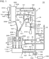
- Fig. 1 is a diagram showing an apparatus 10 according to the embodiment.
- Fig. 2 is a top view showing a rotating table 212 and a plurality of balls 214 of a crusher 200 shown in Fig. 1 .
- Fig. 3 is a cross-sectional view taken along line A-A' of Fig. 2 .
- the apparatus 10 manufactures an inorganic material (A) from plural kinds of inorganic compounds (A1).
- A inorganic material
- FIG. 1 an upward direction of Fig. 1 refers to an upward direction with respect to the vertical direction
- a downward direction of Fig. 1 refers to a downward direction with respect to the vertical direction.
- Fig. 2 does not show a presser 216.
- a black arrow shows a flow of the plural kinds of inorganic compounds (A1).
- a white arrow shows a flow of inert gas.
- the apparatus 10 includes a blower 100, a crusher 200, a first collector 300, and a system S.
- the blower 100 blows inert gas.
- the crusher 200 repeats vitrifying the plural kinds of inorganic compounds (A1) by mechanical energy and blowing up the plural kinds of vitrified inorganic compounds (A1) by the inert gas blown from the blower 100. At least some of the plural kinds of inorganic compounds (A1) blown up by the inert gas enters into the first collector 300.
- the first collector 300 returns the at least some of the plural kinds of inorganic compounds (A1) to the crusher 200.
- the system S (for example, a pipe Pa, a buffer tank 110, a pipe Pb, a pipe Pc, and a pipe Pi described below) circulates the inert gas from the blower 100 through the crusher 200 and the first collector 300 to the blower 100.
- FIG. 1 A structure of the apparatus 10 will be described using Fig. 1 .
- the apparatus 10 includes the blower 100, the buffer tank 110, the crusher 200, the first collector 300, a first container 310, a second collector 400, a second container 410, a decompressor 500, the pipe Pa, a plurality of pipes Pb, the pipe Pc (second pipe), a pipe Pd, a pipe Pe (first pipe), a pipe Pf (third pipe), a pipe Pg, a pipe Ph (fourth pipe), the pipe Pi, a pipe Pj, a pipe Pk, a pipe Pl, a pipe Pm, a pipe Pn, a pipe Po, a valve Va1, a plurality of valves Vb1, a valve Vc1, a valve Vc2 (second valve), a valve Vc3, a valve Vd1, a valve Ve1 (first valve), a valve Ve2, a valve Vf1 (third valve), a valve Vg1, a valve Vh1, a valve Vh2, a valve Vi1, a valve Vi2, a valve Vj1, a valve Vk
- the pipe Pa communicates to a gas outlet 104 of the blower 100 and a gas inlet 112 of the buffer tank 110.
- the valve Va1 is provided in the pipe Pa.
- Each of the plurality of pipes Pb communicates to each of a plurality of gas outlets 114 of the buffer tank 110 and each of a plurality of gas inlets 202 of the crusher 200.
- Each of the plurality of valves Vb1 are provided in each of the plurality of pipes Pb.
- the plurality of pipes Pb are disposed around the rotating table 212.
- the plurality of pipes Pb are arranged in rotational symmetry about the center (rotation axis R described below) of the rotating table 212.
- the pipe Pc communicates to a material discharge pipe 206 of the crusher 200 and a suction port 302 of the first collector 300.
- the valve Vc1, the valve Vc2, and the valve Vc3 are provided in the pipe Pc and are arranged in this order from the material discharge pipe 206 of the crusher 200 to the suction port 302 of the first collector 300.
- the pipe Pd communicates to a material supply pipe 204 of the crusher 200 and a material discharge port 304 of the first collector 300.
- the valve Vd1 is provided in the pipe Pd.
- the pipe Pe communicates to the first container 310 and a material supply port 308 of the first collector 300.
- the valve Ve1 and the valve Ve2 are provided in the pipe Pe and are arranged in this order from the first container 310 to the material supply port 308 of the first collector 300.
- the valve Ve1 is detachably attached to the pipe Pe together with the first container 310. In other words, when the valve Ve1 is detached from the pipe Pe, the first container 310 and the valve Ve1 can be integrated.
- the pipe Pe is connected to the line Le between the valve Ve1 and the valve Ve2.
- the inside of the pipe Pe can be replaced with a vacuum or inert gas through the line Le. That is, the line Le can reduce the internal pressure of the pipe Pe and can introduce inert gas into the pipe Pe.
- the pipe Pf communicates to a portion of the pipe Pc positioned between the valve Vc1 and the valve Vc2 (that is, between the crusher 200 and the valve Vc2), and a suction port 402 of the second collector 400.
- the valve Vf1 is provided in the pipe Pf.
- the pipe Pg communicates to a portion of the pipe Pc positioned between the valve Vc2 and the valve Vc3, and a gas discharge pipe 406 of the second collector 400.
- the valve Vg1 is provided in the pipe Pg.
- the pipe Ph communicates to the second container 410 and a material discharge port 404 of the second collector 400.
- the valve Vh1 and the valve Vh2 are provided in the pipe Ph and are arranged in this order from the second container 410 to the material discharge port 404 of the second collector 400.
- the pipe Ph is connected to the line Lh between the valve Vh1 and the valve Vh2.
- the inside of the pipe Ph can be replaced with a vacuum or inert gas through the line Lh. That is, the line Lh can reduce the internal pressure of the pipe Ph and can introduce inert gas into the pipe Ph.
- the pipe Pi communicates to a gas discharge port 306 of the first collector 300 and a gas inlet 102 of the blower 100.
- the valve Vi1 and the valve Vi2 are provided in the pipe Pi, and are arranged in this order from the gas discharge port 306 of the first collector 300 to the gas inlet 102 of the blower 100.
- the pipe Pj is connected to a portion of the pipe Pi positioned between the gas discharge port 306 of the first collector 300 and the valve Vi1 and a portion of the pipe Pi positioned between the gas inlet 102 of the blower 100 and the valve Vi2.
- the valve Vj1 is provided in the pipe Pj.
- the pipe Pk communicates to an adjustment port 116 of the buffer tank 110 and an exhaust duct D.
- the valve Vk1 is provided in the pipe Pk.
- the pipe Pl communicates to a gas discharge port 208 of the crusher 200 and the decompressor 500.
- the valve Vl1 is provided in the pipe Pl.
- the pipe Pm communicates to the decompressor 500 and the exhaust duct D.
- the valve Vm1 is provided in the pipe Pm.
- the pipe Pn communicates a portion of the pipe Pl positioned between the gas discharge port 208 of the crusher 200 and the valve Vl1, and the exhaust duct D.
- the valve Vn1 is provided in the pipe Pn.
- the pipe Po is branched from the pipe Pi and communicates to the exhaust duct D.
- the pipe Pi includes an end portion of the pipe Pj positioned between the valve Vi2 and the gas inlet 102 of the blower 100.
- the pipe Po communicates to a portion of the pipe Pi positioned between the above-described portion and the gas inlet 102 of the blower 100, and the exhaust duct D.
- the valve Vo1 is provided in the pipe Po.
- the blower 100 sucks gas in the pipe Pj through the gas inlet 102 of the blower 100.
- the blower 100 discharges, through the gas outlet 104 of the blower 100, the gas sucked through the gas inlet 102 of the blower 100.
- the blower 100 sends the gas to the buffer tank 110 through the pipe Pa.
- the rotation speed of a motor of the blower 100 is changeable by an inverter 106, and the flow rate of the gas sent from the blower 100 is freely changeable depending on the rotation speed of the motor.
- the gas sent from the blower 100 through the pipe Pa enters into the gas inlet 112 of the buffer tank 110.
- the gas in the buffer tank 110 passes through the plurality of gas outlets 114 of the buffer tank 110 and is sent to the crusher 200 through the plurality of pipes Pb.
- the pressure of the gas in the buffer tank 110 is adjusted by the valve Vk1.
- the gas sent from the buffer tank 110 through the plurality of pipes Pb enters into the plurality of gas inlets 202 of the crusher 200.
- a material sent from the first container 310 through the pipe Pe, the first collector 300, and the pipe Pd enters into the material supply pipe 204 of the crusher 200.
- At least some of the material and at least some of the gas in the crusher 200 are discharged through the material discharge pipe 206 of the crusher 200.
- the internal pressure of the crusher 200 can be reduced by the decompressor 500.
- the gas in the crusher 200 can be discharged to the exhaust duct D through the pipe Pn.
- the first collector 300 sucks the material and the gas in the pipe Pc through the suction port 302 of the first collector 300.
- the first collector 300 discharges the material sucked through the suction port 302 of the first collector 300 through the material discharge port 304 of the first collector 300.
- the first collector 300 sends the material to the crusher 200 through the pipe Pd.
- the first collector 300 discharges the gas sucked through the suction port 302 of the first collector 300 through the gas discharge port 306 of the first collector 300.
- the first collector 300 sends the gas to the blower 100 through the pipe Pi.
- the first collector 300 is, for example, a dust collector.
- the second collector 400 sucks the material and the gas in the pipe Pc and the pipe Pf through the suction port 402 of the second collector 400.
- the second collector 400 discharges the material sucked through the suction port 402 of the second collector 400 through the material discharge port 404 of the second collector 400.
- the second collector 400 sends the material to the second container 410 through the pipe Ph.
- the second collector 400 discharges the gas sucked through the suction port 402 of the second collector 400 through the gas discharge pipe 406 of the second collector 400.
- the second collector 400 is, for example, a cyclone dust collector.
- the crusher 200 includes the rotating table 212, the plurality of balls 214, and the presser 216.
- the number of the plurality of balls 214 is seven.
- the number of the plurality of balls 214 is not limited to the example shown in Fig. 2 .
- the rotating table 212 is rotatable about the rotation axis R.
- the rotation axis R of the rotating table 212 passes through the center of the rotating table 212 in a height direction (thickness direction) of the rotating table 212.
- the height direction (thickness direction) of the rotating table 212 is along the vertical direction.
- the plurality of balls 214 are arranged around the rotation axis R of the rotating table 212. Specifically, the plurality of balls 214 are arranged in rotational symmetry about the rotation axis R.
- the plurality of balls 214 rotate together with the rotation of the rotating table 212.
- Each of the plurality of balls 214 is individually rotatable about rotation axis R1 rotating together with the rotation of the rotating table 212.
- each ball 214 passes through the center of the ball 214 in the height direction (thickness direction) of the ball 214.
- the height direction (thickness direction) of the ball 214 is along the vertical direction.
- the presser 216 presses the plurality of balls 214 to the rotating table 212 from a side opposite to the rotating table 212.
- the valve Ve1 and the valve Ve2 are closed, and the plural kinds of inorganic compounds (A1) are contained in the first container 310.
- the first container 310 is detached from the pipe Pe together with the valve Ve1.
- the plural kinds of inorganic compounds (A1) are contained in the first container 310.
- the containing of the plural kinds of inorganic compounds (A1) is implemented in an atmosphere (for example, in a glove box) controlled by the inert gas.
- the first container 310 and the valve Ve1 are attached to the pipe Pe with the valve Ve1 being closed.
- the closed valve Ve1 can prevent the plural kinds of inorganic compounds (A1) in the first container 310 from being exposed to the atmosphere (air).
- the atmosphere in the pipe Pe can be replaced with the inert gas through the line Le connected to the pipe Pe.
- the valve Ve1, the valve Ve2, and the valve Vd1 are opened, and the plural kinds of inorganic compounds (A1) are sent from the first container 310 to the crusher 200 through the pipe Pe, the first collector 300, and the pipe Pd. That is, the first container 310 contains the plural kinds of inorganic compounds (A1) supplied to the crusher 200.
- valve Ve1, the valve Ve2, the valve Vf1, the valve Vg1, the valve Vh1, the valve Vh2, the valve Vj1, the valve Vl1, the valve Vm1, the valve Vn1, and the valve vo1 are closed, and the valve Va1, the valves Vb1, the valve Vc1, the valve Vc2, the valve Vc3, the valve Vd1, the valve Vi1, and the valve Vi2 are opened, and the inert gas is supplied to a portion of the pipe Pi positioned between the valve Vi1 and the valve Vi2.
- the blower 100 is operated while adjusting the internal pressure of the buffer tank 110 using the valve Vk1.
- the system S that is, the system from the blower 100 through the pipe Pa, the buffer tank 110, the pipe Pb, the crusher 200, the pipe Pc, the first collector 300, and the pipe Pi to the blower 100 circulates the inert gas and is closed from the outside (that is, the system S is not exposed to the atmosphere (air)).
- the supply of the inert gas to the portion of the pipe Pi positioned between the valve Vi1 and the valve Vi2 may be conducted before or after supplying the plural kinds of inorganic compounds (A1) from the first container 310 to the crusher 200 or may be conducted while supplying the plural kinds of inorganic compounds (A1) from the first container 310 to the crusher 200.
- the position where the inert gas is supplied does not need to be the portion of the pipe Pi positioned between the valve Vi1 and the valve Vi2 and may be any portion in the system S.
- the inert gas may be supplied to a plurality of portions in the system S (including the portion of the pipe Pi positioned between the valve Vi1 and the valve Vi2).
- the inert gas is nitrogen gas.
- the nitrogen gas is supplied, for example, from a nitrogen gas container through a nitrogen purifier.
- the impurity concentration (for example, the water concentration or the oxygen concentration) in the nitrogen gas can be reduced.
- the water concentration in the nitrogen gas may be 400 ppm or less, preferably 40 ppm or less, and more preferably 2 ppm or less
- the oxygen concentration in the nitrogen gas may be 400 ppm or less, preferably 40 ppm or less, and more preferably 2 ppm or less.
- the inert gas may be, however, gas other than nitrogen gas, such as argon gas.
- the crusher 200 is operated. Specifically, the rotating table 212 is rotated about the rotation axis R, each of the balls 214 is rotated about the rotation axis R1, and the plurality of balls 214 are pressed to the rotating table 212 by the presser 216.
- the operation of the crusher 200 may start before or after supplying the plural kinds of inorganic compounds (A1) from the first container 310 to the crusher 200 or may start while supplying the plural kinds of inorganic compounds (A1) from the first container 310 to the crusher 200.
- the crusher 200 repeats vitrifying the plural kinds of inorganic compounds (A1) using mechanical energy and blowing up the plural kinds of vitrified inorganic compounds (A1) by the inert gas blown from the blower 100, as below.
- the plural kinds of inorganic compounds (A1) supplied from the first container 310 arrive at the center of the rotating table 212 or the periphery thereof (the rotation axis R and the periphery thereof) through the material supply pipe 204.
- shearing stress and compressive stress are applied to the plural kinds of inorganic compounds (A1) in the gap between the rotating table 212 and the balls 214 due to the rotation of the balls 214 and the press of the balls 214 to the rotating table 212 by the presser 216.
- the plural kinds of inorganic compounds (A1) are vitrified by the shearing stress and the compressive stress. That is, mechanical milling is conducted on the plural kinds of inorganic compounds (A1).
- the inert gas flows from the lower side to the upper side of the crusher 200 outside of the rotating table 212. This flow is generated by the inert gas sent from the blower 100 through the gas inlets 202 of the crusher 200.
- the plural kinds of vitrified inorganic compounds (A1) are blown up by the inert gas.
- the rotation speed of the motor of the blower 100 is reduced by the inverter 106.
- the flow rate of the inert gas sent from the blower 100 to the crusher 200 is reduced, and the inorganic compounds (A1) are prevented from exiting from the material discharge pipe 206.
- some other of the plural kinds of inorganic compounds (A1) blown up by the inert gas may enter into the material discharge pipe 206 without returning to the rotating table 212.
- the plural kinds of inorganic compounds (A1) having a small particle size are likely to enter into the material discharge pipe 206 without returning to the rotating table 212.
- the plural kinds of inorganic compounds (A1) in the material discharge pipe 206 are sent to the first collector 300 through the pipe Pc, are sent from the first collector 300 to the material supply pipe 204 of the crusher 200 through the pipe Pd, and return to the rotating table 212. Accordingly, mechanical milling by the crusher 200 can be conducted on even the plural kinds of inorganic compounds (A1) in the material discharge pipe 206.
- the system S that is the system from the blower 100 through the pipe Pa, the buffer tank 110, the pipe Pb, the crusher 200, the pipe Pc, the first collector 300, and the pipe Pi to the blower 100 circulates the inert gas and is closed from the outside. Accordingly, contact between the plural kinds of inorganic compounds (A1) and air can be reduced.
- the crusher 200 By conducting mechanical milling on the plural kinds of inorganic compounds (A1) by the crusher 200, the plural kinds of inorganic compounds (A1) are vitrified, and the inorganic material (A) is manufactured from the plural kinds of inorganic compounds (A1).
- valve Vc2 is closed, the valve Vf1 and the valve Vg1 are opened, and the inverter 106 connected to the motor of the blower 100 is controlled to increase the rotation speed of the motor of the blower 100, and the flow rate of the inert gas sent to the gas inlets 202 of the crusher 200 increases (at this stage, the valve Vh1 and the valve Vh2 are closed).
- the inorganic material (A) blown up by the inert gas in the crusher 200 is sent into the material discharge pipe 206 without substantially or completely returning to the rotating table 212.
- the inorganic material (A) sent into the material discharge pipe 206 enters into the suction port 402 of the second collector 400 through the pipe Pc and the pipe Pf.
- the inorganic material (A) is collected by the second collector 400.
- the valve Vh1 and the valve Vh2 are opened.
- the inorganic material (A) collected by the second collector 400 enters into the second container 410 through the pipe Ph.
- the valve Vh1 and the valve Vh2 are closed.
- the second container 410 is detached from the pipe Ph. In this case, the inside of the pipe Ph can be prevented from being exposed to the atmosphere (air) by the closed valve Vh1 and valve Vh2.
- the atmosphere in the pipe Ph can be replaced with the inert gas through the line Lh connected to the pipe Ph.
- the inorganic material (A) passes through the pipe Ph, the inorganic material (A) can be prevented from being exposed to the atmosphere (air).
- the inside of the crusher 200 may be exposed to the atmosphere (air), for example, when an internal component (for example, the rotating table 212, the balls 214, or the presser 216) of the crusher 200 is cleaned.
- the air in the crusher 200 can be removed by reducing the internal pressure of the crusher 200 using the decompressor 500.
- the decompressor 500 can be operated with the plurality of valves Vb1, the valve Vc1, the valve Vd1, and the valve Vn1 closed, and with the valve Vl1 and the valve Vm1 opened.
- an inorganic material (B) having improved crystallinity By heating the inorganic material (A), an inorganic material (B) having improved crystallinity can be formed.
- the inorganic material (B) is not particularly limited, and examples thereof include an inorganic solid electrolyte material, a positive electrode active material, a negative electrode active material, and the like.
- the inorganic solid electrolyte material is not particularly limited, and examples thereof include a sulfide-based inorganic solid electrolyte material, an oxide-based inorganic solid electrolyte material, and other lithium-based inorganic solid electrolyte materials. Among these, a sulfide-based inorganic solid electrolyte material is preferable.
- the inorganic solid electrolyte material is not particularly limited, and examples thereof include an inorganic solid electrolyte material used for a solid electrolyte layer forming an all-solid-state lithium ion battery.
- Examples of the sulfide-based inorganic solid electrolyte material include a Li 2 S-P 2 S 5 material, a Li 2 S-SiS 2 material, a Li 2 S-GeS 2 material, a Li 2 S-Al 2 S 3 material, a Li 2 S-SiS 2 -Li 3 PO 4 material, a Li 2 S-P 2 S 5 -GeS 2 material, a Li 2 S-Li 2 O-P 2 S 5 -SiS 2 material, a Li 2 S-GeS 2 -P 2 S 5 -SiS 2 material, a Li 2 S-SnS 2 -P 2 S 5 -SiS 2 material, a Li 2 S-P 2 S 5 -Li 3 N material, a Li 2 S 2+X -P 4 S 3 material, a Li 2 S-P 2 S 5 -P 4 S 3 material, and the like.
- the Li 2 S-P 2 S 5 material and the Li 2 S-P 2 S 5 -Li 3 N material are preferable from the viewpoint that they have excellent lithium ionic conductivity and has stability to the extent that decomposition or the like does not occur in a wide voltage range.
- the Li 2 S-P 2 S 5 material refers to an inorganic material obtained by a chemical reaction of an inorganic composition including at least Li 2 S (lithium sulfide) and P 2 S 5 by mechanical energy
- the Li 2 S-P 2 S 5 -Li 3 N material refers to an inorganic material obtained by a chemical reaction of an inorganic composition including at least Li 2 S (lithium sulfide), P 2 S 5 , and Li 3 N by mechanical energy.
- examples of the lithium sulfide include lithium polysulfide.
- oxide-based inorganic solid electrolyte material examples include: a NASICON type such as LiTi 2 (PO 4 ) 3 , LiZr 2 (PO 4 ) 3 , or LiGe 2 (PO 4 ) 3 ; a perovskite type such as (La 0.5+x Li 0.5-3x )TiO 3 ; a Li 2 O-P 2 O 5 material; a Li 2 O-P 2 O 5 -Li 3 N material; and the like.
- lithium-based inorganic solid electrolyte material examples include LiPON, LiNbO 3 , LiTaO 3 , Li 3 PO 4 , LiPO 4-x N x (x satisfies 0 ⁇ x ⁇ 1), LiN, LiI, LISICON, and the like.
- a glass ceramic obtained by precipitating crystal of the inorganic solid electrolytes may also be used as the inorganic solid electrolyte material.
- the sulfide-based inorganic solid electrolyte material includes Li, P, and S as constituent elements.
- a molar ratio (Li/P) of the content of Li to the content of P in the solid electrolyte material is preferably 1.0 or higher and 10.0 or lower, more preferably 2.0 or higher and 5.0 or lower, still more preferably 2.5 or higher and 4.0 or lower, still more preferably 2.8 or higher and 3.6 or lower, still more preferably 3.0 or higher and 3.5 or lower, still more preferably 3.1 or higher and 3.4 or lower, and still more preferably 3.1 or higher and 3.3 or lower.
- a molar ratio (S/P) of the content of S to the content of P is preferably 1.0 or higher and 10.0 or lower, more preferably 2.0 or higher and 6.0 or lower, more preferably 3.0 or higher and 5.0 or lower, still more preferably 3.5 or higher and 4.5 or lower, still more preferably 3.8 or higher and 4.2 or lower, still more preferably 3.9 or higher and 4.1 or lower, and still more preferably 4.0.
- the contents of Li, P, and S in the solid electrolyte material can be obtained, for example, by ICP optical emission spectroscopy or X-ray photoelectron spectroscopy.
- Examples of the shape of the sulfide-based inorganic solid electrolyte material include a particle shape.
- the inorganic solid electrolyte material having a particle shape is not particularly limited, and an average particle size d 50 in a weight-based particle size distribution measured using a laser-diffraction scattering method particle size distribution measurement is preferably 1 ⁇ m or more and 100 ⁇ m or less, more preferably 3 ⁇ m or more and 80 ⁇ m or less, still more preferably 5 ⁇ m or more and 60 ⁇ m or less.
- the average particle size d 50 of the inorganic solid electrolyte material is in the above-described range, the lithium ionic conductivity of the obtained solid electrolyte membrane can be further improved while maintaining excellent handling properties.
- the positive electrode active material is not particularly limited, and examples thereof include a positive electrode active material that can be used for a positive electrode layer of a lithium ion battery.
- a sulfide-based positive electrode active material is preferable, and a Li-Mo-S compound, a Li-Ti-S compound, or a Li-V-S compound is more preferable.
- the Li-Mo-S compound includes Li, Mo, and S as constituent elements and can be typically obtained by a chemical reaction of an inorganic composition including molybdenum sulfide and lithium sulfide as raw materials by mechanical energy.
- the Li-Ti-S compound includes Li, Ti, and S as constituent elements and can be typically obtained by a chemical reaction of an inorganic composition including titanium sulfide and lithium sulfide as raw materials by mechanical energy.
- the Li-V-S compound includes Li, V, and S as constituent elements and can be typically obtained by a chemical reaction of an inorganic composition including vanadium sulfide and lithium sulfide as raw materials by mechanical energy.
- the negative electrode active material is not particularly limited, and examples thereof include a negative electrode active material that can be used for a negative electrode layer of a lithium ion battery.
- examples of the negative electrode active material include: a metal material mainly formed of a lithium alloy, a tin alloy, a silicon alloy, a gallium alloy, an indium alloy, or an aluminum alloy; a lithium titanium composite oxide (for example, Li 4 Ti 5 O 12 ), a graphite material, and the like.
- Examples of the plural kinds of inorganic compounds (A1) include a material to be the inorganic material (B) by mechanical milling and heating.
- the plural kinds of inorganic compounds (A1) include Li.
- Fig. 4 is a diagram showing a modification example of Fig. 3 .
- the crusher 200 further includes a cover portion 220.
- the cover portion 220 is positioned above the presser 216. As indicated by white arrows extending along the cover portion 220 in Fig. 4 , the cover portion 220 directs the flow of the inert gas blowing up the plural kinds of inorganic compounds (A1), to the center of the crusher 200 (the rotation axis R of the rotating table 212) and a downward direction of the crusher 200.
- the amount of the plural kinds of inorganic compounds (A1) blown up by the inert gas to enter into the material discharge pipe 206 can be reduced, and the amount of the plural kinds of inorganic compounds (A1) blown up by the inert gas to return to the rotating table 212 can be increased. Accordingly, as compared to when the cover portion 220 is not provided, the efficiency of mechanical milling of the crusher 200 can be improved.
- the crusher 200 presses the balls 214 against the rotating table 212 with the presser 216.
- the presser 216 may press rollers against the rotating table 212 instead of the balls 214.
- the crusher 200 can conduct mechanical milling on the plural kinds of inorganic compounds (A1).
Landscapes
- Chemical & Material Sciences (AREA)
- Engineering & Computer Science (AREA)
- Food Science & Technology (AREA)
- Chemical Kinetics & Catalysis (AREA)
- General Chemical & Material Sciences (AREA)
- Manufacturing & Machinery (AREA)
- Electrochemistry (AREA)
- Organic Chemistry (AREA)
- Inorganic Chemistry (AREA)
- Condensed Matter Physics & Semiconductors (AREA)
- Physics & Mathematics (AREA)
- General Physics & Mathematics (AREA)
- Disintegrating Or Milling (AREA)
- Materials Engineering (AREA)
- Geochemistry & Mineralogy (AREA)
- Life Sciences & Earth Sciences (AREA)
- Glass Melting And Manufacturing (AREA)
- Crushing And Grinding (AREA)
- Physical Or Chemical Processes And Apparatus (AREA)
Claims (10)
- Appareil de fabrication d'un matériau inorganique, l'appareil comprenant :une soufflerie soufflant du gaz inerte ;un broyeur répétant la vitrification de plusieurs types de composés inorganiques destinés à devenir le matériau inorganique par énergie mécanique et faisant exploser les plusieurs types de composés inorganiques vitrifiés par le gaz inerte soufflé par la soufflerie ;un premier collecteur dans lequel entrent au moins certains des plusieurs types de composés inorganiques explosés par le gaz inerte, le premier collecteur renvoyant les au moins certains des plusieurs types de composés inorganiques au broyeur ; etun système faisant circuler le gaz inerte provenant de la soufflerie à travers le broyeur et le premier collecteur vers la soufflerie,dans lequel le système est fermé de l'extérieur.
- Appareil selon la revendication 1 comprenant en outre :un premier récipient contenant les plusieurs types de composés inorganiques destinés à être fournis au broyeur ;un premier tuyau raccordé au premier collecteur et au premier récipient ; etune première vanne fixée de manière détachable au premier tuyau avec le premier récipient.
- Appareil selon la revendication 2 comprenant en outre :
une première conduite introduisant du gaz inerte dans le premier tuyau. - Appareil selon l'une quelconque des revendications 1 à 3, comprenant en outre :un deuxième collecteur dans lequel entre le matériau inorganique explosé par le gaz inerte ;un deuxième tuyau communiquant avec le broyeur et le premier collecteur ;une deuxième vanne prévue dans le deuxième tuyau ;un troisième tuyau communiquant avec une partie du deuxième tuyau positionné entre le broyeur et la deuxième vanne, et le deuxième collecteur ; etune troisième vanne prévue dans le troisième tuyau.
- Appareil selon la revendication 4, comprenant en outre :un deuxième récipient contenant le matériau inorganique collecté par le deuxième collecteur ;un quatrième tuyau communiquant avec le deuxième collecteur et le deuxième récipient ; etune deuxième conduite introduisant du gaz inerte dans le quatrième tuyau.
- Appareil selon l'une quelconque des revendications 1 à 5, comprenant en outre :
un décompresseur réduisant une pression interne du broyeur. - Appareil selon l'une quelconque des revendications 1 à 6,
dans lequel le broyeur comprend une table rotative, une pluralité de billes et un presseur, la pluralité de billes étant agencées autour d'un axe de rotation de la table rotative, chacune de la pluralité de billes pouvant tourner autour d'un axe de rotation tournant conjointement à la rotation de la table rotative, le presseur pressant la pluralité de billes sur la table rotative à partir d'un côté opposé à la table rotative. - Appareil selon l'une quelconque des revendications 1 à 7,
dans lequel le broyeur comprend une partie de capot dirigeant un écoulement du gaz inerte faisant exploser les plusieurs types de composés inorganiques, vers un centre du broyeur et une direction descendante du broyeur. - Appareil selon l'une quelconque des revendications 1 à 8,
dans lequel les plusieurs types de composés inorganiques comprennent le Li. - Procédé de fabrication d'un matériau inorganique, le procédé comprenant :par une soufflerie, le soufflage de gaz inerte ;par un broyeur, la répétition de la vitrification de plusieurs types de composés inorganiques destinés à devenir le matériau inorganique par énergie mécanique et l'explosion des plusieurs types de composés inorganiques vitrifiés par le gaz inerte soufflé par la soufflerie ;le renvoi depuis un premier collecteur au broyeur d'au moins certains des plusieurs types de composés inorganiques explosés par le gaz inerte et l'entrée dans le premier collecteur ; etpar un système, la circulation du gaz inerte provenant de la soufflerie à travers le broyeur et le premier collecteur vers la soufflerie,dans lequel le système est fermé de l'extérieur.
Applications Claiming Priority (2)
| Application Number | Priority Date | Filing Date | Title |
|---|---|---|---|
| JP2019181878 | 2019-10-02 | ||
| PCT/JP2020/031130 WO2021065227A1 (fr) | 2019-10-02 | 2020-08-18 | Dispositif de production de matériau inorganique et procédé de production de matériau inorganique |
Publications (3)
| Publication Number | Publication Date |
|---|---|
| EP4039657A1 EP4039657A1 (fr) | 2022-08-10 |
| EP4039657A4 EP4039657A4 (fr) | 2022-11-23 |
| EP4039657B1 true EP4039657B1 (fr) | 2025-04-16 |
Family
ID=75337852
Family Applications (1)
| Application Number | Title | Priority Date | Filing Date |
|---|---|---|---|
| EP20871660.5A Active EP4039657B1 (fr) | 2019-10-02 | 2020-08-18 | Dispositif de production de matériau inorganique et procédé de production de matériau inorganique |
Country Status (6)
| Country | Link |
|---|---|
| US (1) | US20220339700A1 (fr) |
| EP (1) | EP4039657B1 (fr) |
| JP (2) | JP7266111B2 (fr) |
| KR (4) | KR102760048B1 (fr) |
| CN (2) | CN116273345B (fr) |
| WO (1) | WO2021065227A1 (fr) |
Families Citing this family (5)
| Publication number | Priority date | Publication date | Assignee | Title |
|---|---|---|---|---|
| JP7729752B2 (ja) * | 2021-08-11 | 2025-08-26 | 古河機械金属株式会社 | 硫化物系無機固体電解質材料、固体電解質膜および全固体型リチウムイオン電池 |
| JP7780887B2 (ja) * | 2021-08-11 | 2025-12-05 | 古河機械金属株式会社 | 無機材料を製造する装置及び無機材料を製造する方法 |
| EP4386779A4 (fr) * | 2021-08-11 | 2025-04-02 | Furukawa Co., Ltd. | Matériau d'électrolyte solide inorganique à base de sulfure, membrane électrolyte solide, batterie lithium-ion tout solide, appareil de fabrication de matériau d'électrolyte solide inorganique à base de sulfure et procédé de fabrication de matériau d'électrolyte solide inorganique à base de sulfure |
| JP2025075243A (ja) * | 2023-10-31 | 2025-05-15 | トヨタ自動車株式会社 | 硫化物固体電解質、電池および硫化物固体電解質の製造方法 |
| WO2026071783A1 (fr) * | 2024-09-30 | 2026-04-02 | 주식회사 엘지화학 | Appareil de pulvérisation de matériau d'électrode positive |
Family Cites Families (35)
| Publication number | Priority date | Publication date | Assignee | Title |
|---|---|---|---|---|
| US834387A (en) * | 1904-12-19 | 1906-10-30 | George C Little | Mill for crushing and grinding. |
| US1628609A (en) * | 1922-04-17 | 1927-05-10 | Allis Chalmers Mfg Co | Process of treating combustible material |
| US1822999A (en) * | 1928-05-10 | 1931-09-15 | Peters Claudius | Pulverizing mill |
| GB351129A (en) * | 1930-04-08 | 1931-06-25 | Sydney Asline Ward | Improvements in or relating to apparatus for separating or sorting crushed material |
| US2327402A (en) * | 1940-06-10 | 1943-08-24 | Clarkiron Inc | Grinding mill |
| US3606179A (en) * | 1969-10-21 | 1971-09-20 | Foster Wheeler Corp | Pulverizer |
| US3854666A (en) * | 1973-01-29 | 1974-12-17 | Gilbert Associates | Process for pulverizing coal to ultrafine size |
| DE3545828A1 (de) * | 1985-12-23 | 1987-07-02 | Jackering Altenburger Masch | Verfahren und einrichtung zum betrieb einer mahlanlage |
| US4887773A (en) * | 1986-10-27 | 1989-12-19 | Inco Alloys International, Inc. | Rotary mill with charging system |
| JP2914572B2 (ja) * | 1989-11-15 | 1999-07-05 | バブコツク日立株式会社 | 微粉炭機 |
| AU663829B2 (en) * | 1993-09-03 | 1995-10-19 | Plant Management Consultants (Pty) Limited | Method of and means for controlling a ball mill crusher |
| JP2715861B2 (ja) * | 1993-10-04 | 1998-02-18 | 株式会社栗本鐵工所 | メカノケミカルによる非金属アモルファスの製造方法およびその装置 |
| JPH10230179A (ja) * | 1997-02-18 | 1998-09-02 | Kawasaki Heavy Ind Ltd | 竪型ローラミルによるセメントクリンカの粉砕方法および装置 |
| US6193176B1 (en) * | 1997-02-18 | 2001-02-27 | Kawasaki Jukogyo Kabushiki Kaisha | Cement clinker grinding method using vertical roller mill and apparatus |
| US6076752A (en) * | 1998-06-01 | 2000-06-20 | Quality Botanical Ingredients, Inc. | Method and apparatus for inert gas purging/temperature control for pulverizing/grinding system |
| DE10152991A1 (de) * | 2001-10-26 | 2003-05-08 | Wolff Walsrode Ag | Verfahren und Vorrichtung zur Mahltrocknung |
| JP4813767B2 (ja) * | 2004-02-12 | 2011-11-09 | 出光興産株式会社 | リチウムイオン伝導性硫化物系結晶化ガラス及びその製造方法 |
| JP4550486B2 (ja) * | 2004-05-13 | 2010-09-22 | バブコック日立株式会社 | 分級機およびそれを備えた竪型粉砕機、ならびにその竪型粉砕機を備えた石炭焚ボイラ装置 |
| JP5178241B2 (ja) * | 2008-02-29 | 2013-04-10 | 光夫 成瀬 | 固液分離装置及びこれを用いた固液分離方法 |
| JP5680288B2 (ja) * | 2008-07-07 | 2015-03-04 | トヨタ自動車株式会社 | 硫化物系固体電解質の製造方法 |
| DE102010036176A1 (de) * | 2010-09-02 | 2012-03-08 | Loesche Gmbh | Verfahren und Anlage zur Kohlenvermahlung im Inertbetrieb oder im nicht inerten Betrieb |
| PT2445638E (pt) * | 2010-11-22 | 2013-09-09 | Loesche Gmbh | Moinho de rolos transportável e instalação de moagem transportável |
| JP2012254429A (ja) * | 2011-06-10 | 2012-12-27 | Ihi Corp | 竪型ローラミルのイナート装置 |
| JP6057146B2 (ja) * | 2012-04-25 | 2017-01-11 | 宇部興産機械株式会社 | 粉砕システム |
| JP6288716B2 (ja) | 2014-06-25 | 2018-03-07 | 国立大学法人東京工業大学 | 硫化物固体電解質材料の製造方法 |
| CN105363541A (zh) * | 2015-11-28 | 2016-03-02 | 南阳福森镁粉有限公司 | 一种金属镁粉碎分级装置及其工艺方法 |
| JP6629605B2 (ja) * | 2016-01-27 | 2020-01-15 | 三菱日立パワーシステムズ株式会社 | 分級機、粉砕分級装置及び微粉炭焚きボイラ |
| JP6773456B2 (ja) * | 2016-06-03 | 2020-10-21 | 古河機械金属株式会社 | 無機材料の製造方法 |
| KR101761319B1 (ko) * | 2017-01-24 | 2017-07-25 | 이주선 | 갈탄 건조 시스템 및 갈탄 건조 방법 |
| JP6901295B2 (ja) * | 2017-03-17 | 2021-07-14 | 古河機械金属株式会社 | 無機材料の製造方法 |
| JP6993795B2 (ja) * | 2017-06-07 | 2022-01-14 | 川崎重工業株式会社 | 粉砕システム |
| CN207243927U (zh) * | 2017-09-23 | 2018-04-17 | 武钢集团昆明钢铁股份有限公司 | 一种高效节能的kr铁水预处理脱硫剂布料装置 |
| JP2019181878A (ja) | 2018-04-16 | 2019-10-24 | トヨタ自動車株式会社 | 切断方法 |
| CN108328907B (zh) * | 2018-05-03 | 2020-11-13 | 信和光能(安徽)有限公司 | 一种玻璃生产方法 |
| JP7166454B2 (ja) * | 2019-06-14 | 2022-11-07 | 古河機械金属株式会社 | 無機材料の製造方法及び無機材料製造装置 |
-
2020
- 2020-08-18 CN CN202310295787.8A patent/CN116273345B/zh active Active
- 2020-08-18 KR KR1020247033810A patent/KR102760048B1/ko active Active
- 2020-08-18 KR KR1020257001718A patent/KR20250012746A/ko active Pending
- 2020-08-18 EP EP20871660.5A patent/EP4039657B1/fr active Active
- 2020-08-18 KR KR1020237040446A patent/KR102720347B1/ko active Active
- 2020-08-18 KR KR1020227011051A patent/KR102610432B1/ko active Active
- 2020-08-18 US US17/765,958 patent/US20220339700A1/en active Pending
- 2020-08-18 JP JP2021550409A patent/JP7266111B2/ja active Active
- 2020-08-18 WO PCT/JP2020/031130 patent/WO2021065227A1/fr not_active Ceased
- 2020-08-18 CN CN202080062128.4A patent/CN114423526B/zh active Active
-
2023
- 2023-04-17 JP JP2023067010A patent/JP7498333B2/ja active Active
Also Published As
| Publication number | Publication date |
|---|---|
| JP7498333B2 (ja) | 2024-06-11 |
| CN116273345B (zh) | 2025-09-12 |
| EP4039657A4 (fr) | 2022-11-23 |
| CN116273345A (zh) | 2023-06-23 |
| KR20220059954A (ko) | 2022-05-10 |
| JP7266111B2 (ja) | 2023-04-27 |
| US20220339700A1 (en) | 2022-10-27 |
| WO2021065227A1 (fr) | 2021-04-08 |
| EP4039657A1 (fr) | 2022-08-10 |
| JP2023100681A (ja) | 2023-07-19 |
| KR20230163595A (ko) | 2023-11-30 |
| KR102610432B1 (ko) | 2023-12-05 |
| KR20250012746A (ko) | 2025-01-24 |
| KR102720347B1 (ko) | 2024-10-21 |
| KR20240152964A (ko) | 2024-10-22 |
| KR102760048B1 (ko) | 2025-01-23 |
| JPWO2021065227A1 (fr) | 2021-04-08 |
| CN114423526B (zh) | 2023-04-04 |
| CN114423526A (zh) | 2022-04-29 |
Similar Documents
| Publication | Publication Date | Title |
|---|---|---|
| EP4039657B1 (fr) | Dispositif de production de matériau inorganique et procédé de production de matériau inorganique | |
| JP7502524B2 (ja) | 硫化物系無機固体電解質材料、固体電解質、固体電解質膜およびリチウムイオン電池 | |
| CN110574208A (zh) | 全固态电池 | |
| JP7332761B2 (ja) | 硫化物系無機固体電解質材料、固体電解質、固体電解質膜およびリチウムイオン電池 | |
| KR20200096738A (ko) | 부극층 및 전고체 전지 | |
| JP7688661B2 (ja) | 無機固体電解質材料、固体電解質、固体電解質膜およびリチウムイオン電池 | |
| JP7477602B2 (ja) | 硫化物系無機固体電解質材料、固体電解質、固体電解質膜およびリチウムイオン電池 | |
| KR102630765B1 (ko) | 무기재료의 제조방법 | |
| US12418045B2 (en) | Phosphorus sulfide composition for sulfide-based inorganic solid electrolyte material | |
| JP7596404B2 (ja) | 硫化物系無機固体電解質材料、固体電解質、固体電解質膜およびリチウムイオン電池 | |
| JP7780887B2 (ja) | 無機材料を製造する装置及び無機材料を製造する方法 | |
| JP7729752B2 (ja) | 硫化物系無機固体電解質材料、固体電解質膜および全固体型リチウムイオン電池 | |
| EP4386779A1 (fr) | Matériau d'électrolyte solide inorganique à base de sulfure, membrane électrolyte solide, batterie lithium-ion tout solide, appareil de fabrication de matériau d'électrolyte solide inorganique à base de sulfure et procédé de fabrication de matériau d'électrolyte solide inorganique à base de sulfure | |
| JP7221114B2 (ja) | 無機材料の製造方法 | |
| KR20250038364A (ko) | 전고체 이차전지용 황화물계 고체전해질 제조 | |
| JP2022130434A (ja) | 硫化物系無機固体電解質材料、固体電解質、固体電解質膜およびリチウムイオン電池 |
Legal Events
| Date | Code | Title | Description |
|---|---|---|---|
| STAA | Information on the status of an ep patent application or granted ep patent |
Free format text: STATUS: THE INTERNATIONAL PUBLICATION HAS BEEN MADE |
|
| PUAI | Public reference made under article 153(3) epc to a published international application that has entered the european phase |
Free format text: ORIGINAL CODE: 0009012 |
|
| STAA | Information on the status of an ep patent application or granted ep patent |
Free format text: STATUS: REQUEST FOR EXAMINATION WAS MADE |
|
| 17P | Request for examination filed |
Effective date: 20220324 |
|
| AK | Designated contracting states |
Kind code of ref document: A1 Designated state(s): AL AT BE BG CH CY CZ DE DK EE ES FI FR GB GR HR HU IE IS IT LI LT LU LV MC MK MT NL NO PL PT RO RS SE SI SK SM TR |
|
| A4 | Supplementary search report drawn up and despatched |
Effective date: 20221024 |
|
| RIC1 | Information provided on ipc code assigned before grant |
Ipc: C01B 17/22 20060101ALI20221018BHEP Ipc: H01M 10/0562 20100101ALI20221018BHEP Ipc: H01M 10/052 20100101ALI20221018BHEP Ipc: H01B 13/00 20060101ALI20221018BHEP Ipc: B02C 23/34 20060101ALI20221018BHEP Ipc: B02C 15/12 20060101ALI20221018BHEP Ipc: B01J 19/18 20060101ALI20221018BHEP Ipc: C03B 8/00 20060101AFI20221018BHEP |
|
| DAV | Request for validation of the european patent (deleted) | ||
| DAX | Request for extension of the european patent (deleted) | ||
| GRAP | Despatch of communication of intention to grant a patent |
Free format text: ORIGINAL CODE: EPIDOSNIGR1 |
|
| STAA | Information on the status of an ep patent application or granted ep patent |
Free format text: STATUS: GRANT OF PATENT IS INTENDED |
|
| INTG | Intention to grant announced |
Effective date: 20250109 |
|
| RIN1 | Information on inventor provided before grant (corrected) |
Inventor name: SAKAIRI, YOSHITAKA Inventor name: YAGUCHI, YUICHI |
|
| GRAS | Grant fee paid |
Free format text: ORIGINAL CODE: EPIDOSNIGR3 |
|
| GRAA | (expected) grant |
Free format text: ORIGINAL CODE: 0009210 |
|
| STAA | Information on the status of an ep patent application or granted ep patent |
Free format text: STATUS: THE PATENT HAS BEEN GRANTED |
|
| AK | Designated contracting states |
Kind code of ref document: B1 Designated state(s): AL AT BE BG CH CY CZ DE DK EE ES FI FR GB GR HR HU IE IS IT LI LT LU LV MC MK MT NL NO PL PT RO RS SE SI SK SM TR |
|
| REG | Reference to a national code |
Ref country code: GB Ref legal event code: FG4D |
|
| REG | Reference to a national code |
Ref country code: CH Ref legal event code: EP Ref country code: DE Ref legal event code: R096 Ref document number: 602020049702 Country of ref document: DE |
|
| REG | Reference to a national code |
Ref country code: IE Ref legal event code: FG4D |
|
| REG | Reference to a national code |
Ref country code: SE Ref legal event code: TRGR |
|
| REG | Reference to a national code |
Ref country code: NL Ref legal event code: MP Effective date: 20250416 |
|
| PG25 | Lapsed in a contracting state [announced via postgrant information from national office to epo] |
Ref country code: NL Free format text: LAPSE BECAUSE OF FAILURE TO SUBMIT A TRANSLATION OF THE DESCRIPTION OR TO PAY THE FEE WITHIN THE PRESCRIBED TIME-LIMIT Effective date: 20250416 |
|
| REG | Reference to a national code |
Ref country code: AT Ref legal event code: MK05 Ref document number: 1785580 Country of ref document: AT Kind code of ref document: T Effective date: 20250416 |
|
| PG25 | Lapsed in a contracting state [announced via postgrant information from national office to epo] |
Ref country code: PT Free format text: LAPSE BECAUSE OF FAILURE TO SUBMIT A TRANSLATION OF THE DESCRIPTION OR TO PAY THE FEE WITHIN THE PRESCRIBED TIME-LIMIT Effective date: 20250818 Ref country code: FI Free format text: LAPSE BECAUSE OF FAILURE TO SUBMIT A TRANSLATION OF THE DESCRIPTION OR TO PAY THE FEE WITHIN THE PRESCRIBED TIME-LIMIT Effective date: 20250416 Ref country code: ES Free format text: LAPSE BECAUSE OF FAILURE TO SUBMIT A TRANSLATION OF THE DESCRIPTION OR TO PAY THE FEE WITHIN THE PRESCRIBED TIME-LIMIT Effective date: 20250416 |
|
| PGFP | Annual fee paid to national office [announced via postgrant information from national office to epo] |
Ref country code: DE Payment date: 20250702 Year of fee payment: 6 |
|
| REG | Reference to a national code |
Ref country code: LT Ref legal event code: MG9D |
|
| PG25 | Lapsed in a contracting state [announced via postgrant information from national office to epo] |
Ref country code: GR Free format text: LAPSE BECAUSE OF FAILURE TO SUBMIT A TRANSLATION OF THE DESCRIPTION OR TO PAY THE FEE WITHIN THE PRESCRIBED TIME-LIMIT Effective date: 20250717 Ref country code: NO Free format text: LAPSE BECAUSE OF FAILURE TO SUBMIT A TRANSLATION OF THE DESCRIPTION OR TO PAY THE FEE WITHIN THE PRESCRIBED TIME-LIMIT Effective date: 20250716 |
|
| PG25 | Lapsed in a contracting state [announced via postgrant information from national office to epo] |
Ref country code: PL Free format text: LAPSE BECAUSE OF FAILURE TO SUBMIT A TRANSLATION OF THE DESCRIPTION OR TO PAY THE FEE WITHIN THE PRESCRIBED TIME-LIMIT Effective date: 20250416 |
|
| PG25 | Lapsed in a contracting state [announced via postgrant information from national office to epo] |
Ref country code: BG Free format text: LAPSE BECAUSE OF FAILURE TO SUBMIT A TRANSLATION OF THE DESCRIPTION OR TO PAY THE FEE WITHIN THE PRESCRIBED TIME-LIMIT Effective date: 20250416 |
|
| PG25 | Lapsed in a contracting state [announced via postgrant information from national office to epo] |
Ref country code: HR Free format text: LAPSE BECAUSE OF FAILURE TO SUBMIT A TRANSLATION OF THE DESCRIPTION OR TO PAY THE FEE WITHIN THE PRESCRIBED TIME-LIMIT Effective date: 20250416 |
|
| PG25 | Lapsed in a contracting state [announced via postgrant information from national office to epo] |
Ref country code: AT Free format text: LAPSE BECAUSE OF FAILURE TO SUBMIT A TRANSLATION OF THE DESCRIPTION OR TO PAY THE FEE WITHIN THE PRESCRIBED TIME-LIMIT Effective date: 20250416 |
|
| PGFP | Annual fee paid to national office [announced via postgrant information from national office to epo] |
Ref country code: FR Payment date: 20250703 Year of fee payment: 6 |
|
| PGFP | Annual fee paid to national office [announced via postgrant information from national office to epo] |
Ref country code: SE Payment date: 20250702 Year of fee payment: 6 |
|
| PG25 | Lapsed in a contracting state [announced via postgrant information from national office to epo] |
Ref country code: RS Free format text: LAPSE BECAUSE OF FAILURE TO SUBMIT A TRANSLATION OF THE DESCRIPTION OR TO PAY THE FEE WITHIN THE PRESCRIBED TIME-LIMIT Effective date: 20250716 |
|
| PG25 | Lapsed in a contracting state [announced via postgrant information from national office to epo] |
Ref country code: IS Free format text: LAPSE BECAUSE OF FAILURE TO SUBMIT A TRANSLATION OF THE DESCRIPTION OR TO PAY THE FEE WITHIN THE PRESCRIBED TIME-LIMIT Effective date: 20250816 |
|
| PG25 | Lapsed in a contracting state [announced via postgrant information from national office to epo] |
Ref country code: LV Free format text: LAPSE BECAUSE OF FAILURE TO SUBMIT A TRANSLATION OF THE DESCRIPTION OR TO PAY THE FEE WITHIN THE PRESCRIBED TIME-LIMIT Effective date: 20250416 |
|
| PG25 | Lapsed in a contracting state [announced via postgrant information from national office to epo] |
Ref country code: SM Free format text: LAPSE BECAUSE OF FAILURE TO SUBMIT A TRANSLATION OF THE DESCRIPTION OR TO PAY THE FEE WITHIN THE PRESCRIBED TIME-LIMIT Effective date: 20250416 Ref country code: DK Free format text: LAPSE BECAUSE OF FAILURE TO SUBMIT A TRANSLATION OF THE DESCRIPTION OR TO PAY THE FEE WITHIN THE PRESCRIBED TIME-LIMIT Effective date: 20250416 |
|
| REG | Reference to a national code |
Ref country code: DE Ref legal event code: R097 Ref document number: 602020049702 Country of ref document: DE |
|
| PG25 | Lapsed in a contracting state [announced via postgrant information from national office to epo] |
Ref country code: CZ Free format text: LAPSE BECAUSE OF FAILURE TO SUBMIT A TRANSLATION OF THE DESCRIPTION OR TO PAY THE FEE WITHIN THE PRESCRIBED TIME-LIMIT Effective date: 20250416 |
|
| PG25 | Lapsed in a contracting state [announced via postgrant information from national office to epo] |
Ref country code: EE Free format text: LAPSE BECAUSE OF FAILURE TO SUBMIT A TRANSLATION OF THE DESCRIPTION OR TO PAY THE FEE WITHIN THE PRESCRIBED TIME-LIMIT Effective date: 20250416 |
|
| PG25 | Lapsed in a contracting state [announced via postgrant information from national office to epo] |
Ref country code: SK Free format text: LAPSE BECAUSE OF FAILURE TO SUBMIT A TRANSLATION OF THE DESCRIPTION OR TO PAY THE FEE WITHIN THE PRESCRIBED TIME-LIMIT Effective date: 20250416 |
|
| PG25 | Lapsed in a contracting state [announced via postgrant information from national office to epo] |
Ref country code: IT Free format text: LAPSE BECAUSE OF FAILURE TO SUBMIT A TRANSLATION OF THE DESCRIPTION OR TO PAY THE FEE WITHIN THE PRESCRIBED TIME-LIMIT Effective date: 20250416 |
|
| PG25 | Lapsed in a contracting state [announced via postgrant information from national office to epo] |
Ref country code: RO Free format text: LAPSE BECAUSE OF FAILURE TO SUBMIT A TRANSLATION OF THE DESCRIPTION OR TO PAY THE FEE WITHIN THE PRESCRIBED TIME-LIMIT Effective date: 20250416 |
|
| PLBE | No opposition filed within time limit |
Free format text: ORIGINAL CODE: 0009261 |
|
| STAA | Information on the status of an ep patent application or granted ep patent |
Free format text: STATUS: NO OPPOSITION FILED WITHIN TIME LIMIT |
|
| REG | Reference to a national code |
Ref country code: CH Ref legal event code: L10 Free format text: ST27 STATUS EVENT CODE: U-0-0-L10-L00 (AS PROVIDED BY THE NATIONAL OFFICE) Effective date: 20260225 |
|
| REG | Reference to a national code |
Ref country code: CH Ref legal event code: H13 Free format text: ST27 STATUS EVENT CODE: U-0-0-H10-H13 (AS PROVIDED BY THE NATIONAL OFFICE) Effective date: 20260324 |
|
| 26N | No opposition filed |
Effective date: 20260119 |
|
| PG25 | Lapsed in a contracting state [announced via postgrant information from national office to epo] |
Ref country code: MC Free format text: LAPSE BECAUSE OF FAILURE TO SUBMIT A TRANSLATION OF THE DESCRIPTION OR TO PAY THE FEE WITHIN THE PRESCRIBED TIME-LIMIT Effective date: 20250416 |
|
| PG25 | Lapsed in a contracting state [announced via postgrant information from national office to epo] |
Ref country code: LU Free format text: LAPSE BECAUSE OF NON-PAYMENT OF DUE FEES Effective date: 20250818 |
|
| PG25 | Lapsed in a contracting state [announced via postgrant information from national office to epo] |
Ref country code: CH Free format text: LAPSE BECAUSE OF NON-PAYMENT OF DUE FEES Effective date: 20250831 |