EP4039736A1 - Patin de frein a disque - Google Patents
Patin de frein a disque Download PDFInfo
- Publication number
- EP4039736A1 EP4039736A1 EP20872230.6A EP20872230A EP4039736A1 EP 4039736 A1 EP4039736 A1 EP 4039736A1 EP 20872230 A EP20872230 A EP 20872230A EP 4039736 A1 EP4039736 A1 EP 4039736A1
- Authority
- EP
- European Patent Office
- Prior art keywords
- heat history
- friction material
- friction
- area
- scorch treatment
- Prior art date
- Legal status (The legal status is an assumption and is not a legal conclusion. Google has not performed a legal analysis and makes no representation as to the accuracy of the status listed.)
- Granted
Links
Images



Classifications
-
- F—MECHANICAL ENGINEERING; LIGHTING; HEATING; WEAPONS; BLASTING
- F16—ENGINEERING ELEMENTS AND UNITS; GENERAL MEASURES FOR PRODUCING AND MAINTAINING EFFECTIVE FUNCTIONING OF MACHINES OR INSTALLATIONS; THERMAL INSULATION IN GENERAL
- F16D—COUPLINGS FOR TRANSMITTING ROTATION; CLUTCHES; BRAKES
- F16D65/00—Parts or details
- F16D65/0037—Devices for conditioning friction surfaces, e.g. cleaning or abrasive elements
-
- F—MECHANICAL ENGINEERING; LIGHTING; HEATING; WEAPONS; BLASTING
- F16—ENGINEERING ELEMENTS AND UNITS; GENERAL MEASURES FOR PRODUCING AND MAINTAINING EFFECTIVE FUNCTIONING OF MACHINES OR INSTALLATIONS; THERMAL INSULATION IN GENERAL
- F16D—COUPLINGS FOR TRANSMITTING ROTATION; CLUTCHES; BRAKES
- F16D69/00—Friction linings; Attachment thereof; Selection of coacting friction substances or surfaces
- F16D69/02—Composition of linings ; Methods of manufacturing
-
- F—MECHANICAL ENGINEERING; LIGHTING; HEATING; WEAPONS; BLASTING
- F16—ENGINEERING ELEMENTS AND UNITS; GENERAL MEASURES FOR PRODUCING AND MAINTAINING EFFECTIVE FUNCTIONING OF MACHINES OR INSTALLATIONS; THERMAL INSULATION IN GENERAL
- F16D—COUPLINGS FOR TRANSMITTING ROTATION; CLUTCHES; BRAKES
- F16D65/00—Parts or details
- F16D65/02—Braking members; Mounting thereof
- F16D65/04—Bands, shoes or pads; Pivots or supporting members therefor
- F16D65/092—Bands, shoes or pads; Pivots or supporting members therefor for axially-engaging brakes, e.g. disc brakes
-
- F—MECHANICAL ENGINEERING; LIGHTING; HEATING; WEAPONS; BLASTING
- F16—ENGINEERING ELEMENTS AND UNITS; GENERAL MEASURES FOR PRODUCING AND MAINTAINING EFFECTIVE FUNCTIONING OF MACHINES OR INSTALLATIONS; THERMAL INSULATION IN GENERAL
- F16D—COUPLINGS FOR TRANSMITTING ROTATION; CLUTCHES; BRAKES
- F16D69/00—Friction linings; Attachment thereof; Selection of coacting friction substances or surfaces
-
- F—MECHANICAL ENGINEERING; LIGHTING; HEATING; WEAPONS; BLASTING
- F16—ENGINEERING ELEMENTS AND UNITS; GENERAL MEASURES FOR PRODUCING AND MAINTAINING EFFECTIVE FUNCTIONING OF MACHINES OR INSTALLATIONS; THERMAL INSULATION IN GENERAL
- F16D—COUPLINGS FOR TRANSMITTING ROTATION; CLUTCHES; BRAKES
- F16D69/00—Friction linings; Attachment thereof; Selection of coacting friction substances or surfaces
- F16D69/02—Composition of linings ; Methods of manufacturing
- F16D69/025—Compositions based on an organic binder
- F16D69/026—Compositions based on an organic binder containing fibres
-
- F—MECHANICAL ENGINEERING; LIGHTING; HEATING; WEAPONS; BLASTING
- F16—ENGINEERING ELEMENTS AND UNITS; GENERAL MEASURES FOR PRODUCING AND MAINTAINING EFFECTIVE FUNCTIONING OF MACHINES OR INSTALLATIONS; THERMAL INSULATION IN GENERAL
- F16D—COUPLINGS FOR TRANSMITTING ROTATION; CLUTCHES; BRAKES
- F16D69/00—Friction linings; Attachment thereof; Selection of coacting friction substances or surfaces
- F16D2069/005—Friction linings; Attachment thereof; Selection of coacting friction substances or surfaces having a layered structure
-
- F—MECHANICAL ENGINEERING; LIGHTING; HEATING; WEAPONS; BLASTING
- F16—ENGINEERING ELEMENTS AND UNITS; GENERAL MEASURES FOR PRODUCING AND MAINTAINING EFFECTIVE FUNCTIONING OF MACHINES OR INSTALLATIONS; THERMAL INSULATION IN GENERAL
- F16D—COUPLINGS FOR TRANSMITTING ROTATION; CLUTCHES; BRAKES
- F16D2250/00—Manufacturing; Assembly
- F16D2250/0038—Surface treatment
Definitions
- This invention relates to a disc brake pad used for an automobile disc brake such as a passenger car and a truck and especially relates to a disc brake pad including a friction material having a scorch-treated friction surface.
- a disc brake is used for a brake device for an automobile.
- the disc brake includes a disc brake pad, which is integrated by affixing to a back plate, functioning as the friction material.
- a friction material for a disc brake pad is manufactured by performing a mixing step to obtain a raw friction material mixture by mixing a friction material composition including such as a binder, a fiber base, a lubricant, an organic friction modifier, an inorganic friction modifier, a pH adjuster, and a filler, a heat press forming step for heat-press-forming the raw friction material mixture superposed on a back plate, and a curing step for completing the curing reaction of the resin, which is functioning as the binder.
- a friction material composition including such as a binder, a fiber base, a lubricant, an organic friction modifier, an inorganic friction modifier, a pH adjuster, and a filler
- a heat press forming step for heat-press-forming the raw friction material mixture superposed on a back plate
- a curing step for completing the curing reaction of the resin, which is functioning as the binder.
- the disc brake pad is used in combination with a cast iron disc rotor as a mating member to effectuate a braking force by pressing the friction material of the disc brake pad against the disc rotor while rotating.
- This fading phenomenon causes the reduction of the braking effectiveness because a gas or liquid decomposition product is generated when organic substances such as the binder and the organic friction modifier contained in the friction material of the disc brake pad are exposed to a high temperature and high load condition and are thermally decomposed to be positioned between the friction material and the friction surface of the disc rotor ultimately affecting as a lubricant.
- a scorch treatment that uses such as a heating plate, flame throw and laser irradiation to perform a high temperature heat treatment on the friction surface of the friction material and burns to remove the organic substances, which may be the cause of generating the fading phenomenon.
- Patent Document 1 discloses a manufacturing method for a friction material which is characterized in performing a scorch treatment on an area other than an area from 1mm at the shortest to 10mm at the longest both from the outer circumference of the friction material and a manufacturing method for the friction material which is characterized in re-performing the scorch treatment on the area other than the area from 1mm at the shortest to 10mm at the longest both from the outer circumference of the friction material after performing the scorch treatment on the whole friction surface area.
- the braking effectiveness at the outer circumferential area of the friction material may be improved by inhibiting the decomposition of the substances such as the thermosetting resin and the organic reinforcement fiber when fading without reducing a friction coefficient and a wear resistance; however, a problem remains as a sufficient braking effectiveness may not be secured at the normally used area of the friction material.
- Patent Document 2 uses a disc brake pad that generates a braking force by frictionally contacting the friction material with the disc rotor and discloses the disc brake pad with the scorch treatment on at least one of both sides of the friction material relative to a rotational direction of the disc rotor.
- generation of the braking noise may be inhibited by changing physical characteristics, such as the reduction of the friction coefficient, a reduction of the hardness, a reduction of a strength, and an improvement of hydrophobicity, of the friction material at least one of both sides of the friction material relative to the rotational direction of the disc rotor; however, a problem remains as the fading phenomenon may not be effectively prevented because no scorch treatment is performed on a central area of the friction surface of the friction material.
- a cashew dust is used as an organic friction modifier in friction material of the disc brake pad.
- the cashew dust forms a film on the friction surface of the disc rotor and functions to provide an excellent and stable braking effectiveness as generating an adhesive friction between the disc brake pad and the friction surface.
- the scorch treatment may be performed on the friction surface of the friction material to effectively inhibit the fading phenomenon at the initial stage of the disc brake pad usage as burning and removing the organic substances such as the cashew dust that could be the cause of the generation of the fading phenomenon; however, the problem of insufficient braking effectiveness remains because the film of the cashew dust cannot be formed on the friction surface of the disc rotor after the component of the cashew dust on the friction surface of the friction material is burned and ceases to exist.
- This invention was made to improve the above-problems and to provide a disc brake pad for the use of a disc brake for an automobile, which includes a friction material having a friction material surface on which a scorch treatment is performed.
- An object of this invention is to provide the disc brake pad that achieves a sufficient braking effectiveness and prevents fading phenomenon at an initial stage of the disc brake pad usage.
- Conventional scorch treatments perform a high temperature heat treatment on the friction surface of the friction material to provide a uniform heat history so that a depth of a scorch treatment layer after burning and removing the organic substances becomes uniform from the friction surface.
- Applicant completed this invention after confirming the prevention of the fading phenomenon at the initial stage of the disc brake pad usage and the maintenance of the sufficient braking effect by arranging areas of the friction surface to receive different heat histories due to the scorch treatment and by mixing an area within the friction surface where the organic substances such as the cashew dust are removed and an area of the friction surface where relatively large amount of the organic substances such as the cashew dust remains therein.
- This invention relates to the disc brake pad for the use of automobiles such as a passenger vehicle and a truck, more particularly to the disc brake pad having the friction material with the friction surface on which the scorch treatment is performed and relates to the invention based on the following technology.
- the disc brake pad of this invention can effectively prevent the fading phenomenon at the initial stage of the disc brake pad usage by performing the scorch treatment on the friction surface of the friction material and partially removing the organic substances such as the cashew dust existing in the vicinity of the friction surface of the friction material.
- the friction material of the disc brake pad according to this invention has the friction surface on which the area with large heat history and the area with relatively small heat history both by the scorch treatment are arranged so as to mixed.
- the organic substances such as the cashew dust are removed in the area of the friction surface with the large heat history of the scorch treatment, while relatively large amount of the organic substances such as the cashew dust remains in the area of the friction surface with relatively small heat history of the scorch treatment.
- the cashew dust film may be formed on the friction surface of the disc rotor so that an excellent and stable braking effectiveness can be provided because of the generated adhesive friction o the friction surface.
- This invention may provide the disc brake pad that while preventing the fading phenomenon at the initial stage of the disc brake pad usage, can provide sufficient braking effectiveness.
- the disc brake pad of this invention is explained while referring to FIG. 1 .
- a disc brake pad 10 has a metal back plate 11 and a friction material 12 integrally affixed to one side of the back plate 11.
- a friction surface of the friction material is arranged so that heat histories that the friction surface of the friction material receives due to a scorch treatment are not uniform and an area with large heat history and an area with relatively small heat history both due to scorch treatment are arranged so as to be mixed on the friction surface.
- the scorch treatment is performed on the friction material 12 in a way to create different heat histories on the friction surface of the friction material, so that the large heat history of the scorch treatment (intensive treatment area) 13 and an area with relatively small heat history of the scorch treatment (mild treatment area) 14 are arranged so as to be mixed on the friction surface of the friction material.
- Organic substances such as a cashew dust in a surface layer of the friction material are burned and ceased to exist in the intensive treatment area 13 with large heat history of the scorch treatment on the friction surface, while relatively large amount of the organic substances such as the cashew dust remains in the mild treatment area 14 with relatively small heat history of the scorch treatment on the friction surface comparing to the intensive treatment area 13 with large history of the scorch treatment on the friction material.
- the mild treatment area 14 with relatively small heat history of the scorch treatment can be an area of the friction surface without the heat history of the scorch treatment.
- the heat histories by the scorch treatment on the friction surface of the friction material 12 are arranged so that the heat histories on the friction surface are not uniform and different heat histories of the scorch treatment are arranged so as to be mixed on the friction surface of the friction material 12.
- the reason for arranging the areas having the difference heat histories so as to be mixed on the friction surface of the friction material 12 is to create differences in the amount of the organic substances such as the cashew dust remaining in different areas of the friction surface of the friction material 12 and use the differences to obtain the sufficient braking effectiveness while preventing the fading phenomenon at the initial stage of the usage of a disc brake pad 10.
- the scorch treatment is performed on the friction surface of the friction material 12, and the organic substances such as the cashew dust existing in the vicinity of the friction surface are partially removed, so that the fading phenomenon at the initial stage of the usage of the disc brake pad 10 can effectively be prevented.
- the friction material 12 of the disc brake pad 10 of this invention has the intensive treatment area 13 with large heat history of the scorch treatment and the mild treatment area 14 with relatively small heat history of the scorch treatment comparing to the intensive treatment area 13 with large heat history of the scorch treatment.
- Relatively larger amount of the organic substances such as the cashew dust remains in the mild treatment area 14 with relatively small heat history of the scorch treatment than the intensive treatment area 13 with large heat history of the scorch treatment. Therefore, the cashew dust film can be formed on the friction surface of the disc rotor during the braking action, thereby generating the adhesive friction to provide the excellent and stable braking effectiveness.
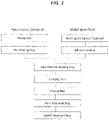
- the method for manufacturing the disc brake pad is explained with reference to FIG. 2 and FIG. 3 .
- a friction material composition containing the predetermined amount of raw friction materials such as a binder, a fiber base, a lubricant, an organic friction modifier, an inorganic friction modifier, a pH adjuster, and a filler, is positioned in a mixer such as Loedige mixer and Eirich mixer to agitate the friction material composition until the friction material composition is uniformly dispersed to obtain a raw friction material mixture.
- a mixer such as Loedige mixer and Eirich mixer to agitate the friction material composition until the friction material composition is uniformly dispersed to obtain a raw friction material mixture.
- the obtained raw friction material mixture is positioned in a preforming die, and a pressing apparatus is used to press-form the raw friction material mixture to obtain an intermediate molded article.
- a kneading step to knead the raw friction material mixture by a pressure kneader before the pre-forming step to obtain a kneaded substance of the raw friction material and a granulating step to granulate the raw friction material mixture to obtain a granulated substance of the raw friction material.
- the intermediate molded article obtained through the pre-forming step is superposed on a pre-washed, pre-surface treated, and adhesive-coated steel back plate to be positioned in a heat forming die and to be heat-press-formed using the pressing apparatus at the temperature of 140 - 200°C under the pressure of 20 - 80MPa for 1 - 10 minutes to obtain the molded article of the friction material.
- the pre-forming step may be omitted, and any one of the raw friction material mixture, the kneaded substance of the raw friction material, or the granulated substance of the raw friction material may be position to process the heat press forming.
- a grinder with a grinding stone may be used to grind the surface of the friction material to form the friction surface.
- a chamfer or a slit may be formed on the surface of the friction material.
- a coating step is performed by coating areas other than the friction surface of the friction material of the disc brake pad by a spray coating or an electrostatic powder coating.
- a baking is conducted in a next heat treatment step.
- the coated molded article is heated at 180 - 250°C for 1 - 5 hours to complete curing of a thermosetting resin contained in the friction material as the binder and at the same time the coating formed during the coating step is baked.
- a vertical cavity surface emitting laser module 20 (hereinafter, surface emitting laser module 20), which is one type of semiconductor lasers, is used as a heating means for the scorch treatment of the friction material 12 formed on one side of the back plate 11, and multiple lasers with different energy densities irradiate the friction surface of the friction material 12, while the surface emitting laser module 20 and the disc brake pad 10 are relatively making a parallel movement, in order to form the friction surface having mixed areas including the area with large heat history of the scorch treatment 13 and the area with relatively small heat history of the scorch treatment 14 comparing to the area with large heat history of the scorch treatment 13.
- the surface emitting laser module 20 is a module on which multiple vertical cavity surface emitting laser (VCSE) elements 21 (hereinafter surface emitting laser element 21) are arranged, and the respective surface emitting laser element 21 is capable of changing an energy density of the laser.
- VCSE vertical cavity surface emitting laser
- the respective surface emitting laser element 21 arranged to face each other on the surface of the friction material 12 is preset to arrange the energy density to provide the heat history of the scorch treatment correspond to the area of the friction surface of the friction material 12, which facilitates forming of the friction surface with the mixed areas including the area with large heat history of the scorch treatment 13 and the area with relatively small heat history of the scorch treatment 14 comparing to the area with large heat history of the scorch treatment 13.
- the surface emitting laser module 20 Vertical Cavity Surface Emitting Laser Module by Philips Photonics Company Limited, which is manufactured such as by the method disclosed in the Japanese Patent Publication No. 2015-51027 , may be used.
- the surface emitting laser element 21 is not limited to the one for the vertical cavity surface emitting laser.
- the energy density for forming the area with large heat history of the scorch treatment 13 is 150 - 1100kW/m 2
- the energy density of the area with relatively small heat history of the scorch treatment 14 comparing to the area with large heat history of the scorch treatment 13 is 0 - 300kW/m 2 .
- a distance (hereinafter irradiation distance) G between an irradiation surface of the surface emitting laser element 21 when performing the scorch treatment of the friction material 12 and the surface of the friction material 12 is 15 - 300mm and is preferably 30 - 200mm but more preferably 50 - 100mm.
- a processing time for the scorch treatment of the friction material 12 is 0.5 - 60 seconds and is preferably 3 - 10 but more preferably 4 - 8 seconds.
- Positions of the surface emitting laser modules 20 relative to the friction material 12 are not limited to the positions in FIG. 3 showing the surface emitting laser module 20 arranged laterally and parallel to the disc brake pad 10. Positions of the surface emitting laser modules 20 may be arranged vertically facing each other on the friction material 12 or may be arranged widening toward the posterior ends to surround the friction material 12.
- Either one of the surface emitting laser module 20 or the disc brake pad 10 makes a parallel movement or both of the surface emitting laser module 20 and the disc brake pad 10 make a parallel movement to form the friction surface having the mixed areas including the area with large heat history of the scorch treatment 13 and the area with relatively small heat history of the scorch treatment 14 comparing to the area with large heat history of the scorch treatment 13.
- the surface pattern of the area with large heat history of the scorch treatment 13 viewing from the friction surface side of the friction material 12 is not limited to the stripe pattern in a vertical direction of the friction material 12 as shown in FIG. 1 .
- the pattern may be one pattern or any combination of the patterns as shown in FIG. 4 such as a stripe pattern in a horizontal direction of the friction material 12 as shown in FIG. 4(a) , an oblique stripe pattern as shown in FIG. 4(b) , a lattice pattern as shown in FIG. 4(c) , and a wave pattern as shown in FIG. 4(d) , and the houndstooth pattern.
- the surface form of the area with large heat history of the scorch treatment 13 is not limited to a straight shape and can be a curve shape.
- the surface form of the area with large heat history of the scorch treatment 13 is not limited to a continuous strip surface but can be a broken strip surface having gaps therebetween and a polka-dot strip surface having a polka-dot pattern.
- a width of the area with large heat history of the scorch treatment 13 and a spacing or an interval between the areas with large heat history of the scorch treatment 13 are determined as appropriate.
- this invention facilitates manufacturing of the disc brake pad 10 having the friction material 12 with the mixed areas including areas of different heat histories of the scorch treatment by irradiating the friction surface of the friction material 12 using multiple lasers with different energy densities while relatively moving the surface emitting laser module 20 and the disc brake pad 10.
- Whether the heat history of the particular area of the friction material 12 due to the scorch treatment is large or small can be determined from the mass reduction rate as the result of thermogravimetric analysis using the surface specimen collected from the surface of the friction material 12 with the heat history of the scorch treatment and the internal specimen collected from the inside of the friction material 12 without the heat history of the scorch treatment.
- a drilling machine is used to drill a hole with a diameter of 6mm and a depth of 0.1mm in two portions of each of the area with large heat history of the scorch treatment 13 and the area with relatively small heat history of the scorch treatment 14 comparing to the area with large heat history of the scorch treatment 13 in order to collect 20mg of specimen from each hole.
- a grinding machine is used to grind from the surface of the friction material 12 with the heat history due to the scorch treatment to the surface of the friction material 12 without the heat history of the scorch treatment, which is 3mm depth.
- the drilling machine is used to drill a hole with a diameter of 6mm and a depth of 0.1mm in order to collect 20mg of the internal specimen.
- the mass reduction rate of the respective specimen Prior to the thermogravimetric analysis of the specimens (the surface specimen and internal specimen) collected from the friction material 12, the mass reduction rate of the respective specimen is defined as follows. A(%) A reduction rate of the mass of the inside of the friction material without the heat history due to the scorch treatment when performing the thermogravimetric analysis of the friction material at 500°C B1(%) A reduction rate of the mass of the friction surface area with the largest heat history due to the scorch treatment 13 when performing the thermogravimetric analysis at 500°C. B2(%) A reduction rate of the mass of the friction surface area with the relatively small heat history due to the scorch treatment 14 relative to the friction surface area with the largest heat history due to the scorch treatment 13 when performing the thermogravimetric analysis at 500°C.
- the reduction rate of the mass of the friction surface when performing the thermogravimetric analysis of the respective specimen collected from the friction material 12 is as follows.
- the reduction rate A of the mass when conducting the thermogravimetric analysis is the largest among all.
- the reduction rate B1 of the mass when conducing the thermogravimetric analysis is the smallest among all.
- the reduction rate B2 of the mass when conducing the thermogravimetric analysis is larger than the reduction rate B1.
- the reduction rate B2 of the mass when conducting the thermogravimetric analysis of the surface of the friction material 12 becomes approximately equal to the reduction rate A of the mass of the internal portion of the friction material 12.
- the area ratio of the area with the largest heat history due to the scorch treatment 13 in the friction surface of the friction material 12 is set to be within the rage of 10 - 90%.
- the area ratio of the area with the largest heat history due to the scorch treatment 13 is preferably within the range of 30 - 70% and is more preferably within the range of 40 - 60%.
- the fading resistance and the braking effectiveness can be improved.
- thermogravimetric analysis is conducted by Thermo plus EVO TG8120 by Rigaku Company Limited under the following conditions.
- a thermogravimetric reduction rate is calculated from the thermogravimetric reduction amount between the room temperature to 500°C.
- the friction material composition with compositions as shown in Table 1 is mixed by Loedige mixer for 5 minutes, and the mixed friction material composition is pressed in the pre-forming die under the pressure of 30MPa for 10 seconds to obtain the intermediate molded article.
- This intermediate molded article is superposed on the pre-washed, surface treated, and adhesive coated steel back plate to be positioned in the heat forming die together with the back plate to be heat-pressed at the temperature of 150°C under the pressure of 40MPa for 10 minutes and is electrostatic powder coated to be heat-treated (post-cured) and baked at the temperature of 200°C for 5 hours to be grinded to form the friction surface.
- Disc brake pads are manufactured by performing the scorch treatment under the conditions in the following Table 2 and Table 3 (Embodiments 1 - 26, Comparative Examples 1 - 9) [Table 3] Comparative Examples 1 2 3 4 5 6 7 8 9 Area with Largest Heat History due to Scorch Treatment Conditions for Scorch Treatment (Area B1) Energy Density of Surface Emitting Laser Element (kW/m2) 120 1000 1150 1150 1150 1150 1150 1000 Distance between Irradiation Surface of Surface Emitting Laser Element and Friction Material Surface (mm) 50 50 50 50 50 50 50 50 50 50 50 50 50 50 50 50 50 50 50 50 50 50 50 50 50 50 50 50 50 50 50 50 50 50 50 50 50 50 50 50 50 50 50 50 50 50 50 50 50 50 50 50 50 50 50 50 50 50 50 50 50 50 50 50 50 50 50 50 50 50 50 50 50 50 50 50 50 50 50 50 50 50 50 50 50 50 50 50 50 50 50 50 50 50 50 50 50 50 50 50 50 50 50 50 50 50 50 50 50 50 50 50 50 50 50 50 50 50 Processing Time
- the fading resistance, the braking effectiveness, the wear resistance, and the flatness level are evaluation for the obtained disc brake pads.
- Evaluation standard is as follows. Evaluation Amount of wear of the friction material (mm) Excellent Less than 0.15mm Good 0.15mm or more but less than 0.20mm Pass 0.20mm or more but less than 0.50mm Fail 0.50mm or more
- Three support blocks are mounted on a surface plate to make uniform in height. These support blocks support three ends of the back plate.
- a dial gauge is used to measure heights of five areas of the friction material with the largest heat history due to the scorch treatment and five areas of the friction material with relatively small heat history due to the scorch treatment comparing to the areas with the largest heat history due to the scorch treatment to determine the difference between the highest height and lowest height.
- Evaluation standard is as follows. Evaluation Flatness level of the friction material ( ⁇ m) Excellent Less than 70 ⁇ m Good 70 ⁇ m or more but less than 100 ⁇ m Pass 100 ⁇ m or more but less than 150 ⁇ m Fail 150 ⁇ m or more
- the respective friction material 12 that satisfies the conditions of this invention shows more sufficient and satisfactory evaluation result with respect to the fading resistance, the braking effectiveness, the wear resistance, and flatness level.
- the disc brake pad offers an excellent practical value by providing, while preventing the fading phenomenon at the initial stage of the disc brake pad usage, the sufficient wear resistance and the braking effectiveness.
Landscapes
- Engineering & Computer Science (AREA)
- General Engineering & Computer Science (AREA)
- Mechanical Engineering (AREA)
- Braking Arrangements (AREA)
Applications Claiming Priority (2)
| Application Number | Priority Date | Filing Date | Title |
|---|---|---|---|
| JP2019183086A JP7375282B2 (ja) | 2019-10-03 | 2019-10-03 | ディスクブレーキパッド |
| PCT/JP2020/036627 WO2021065797A1 (fr) | 2019-10-03 | 2020-09-28 | Patin de frein a disque |
Publications (3)
| Publication Number | Publication Date |
|---|---|
| EP4039736A1 true EP4039736A1 (fr) | 2022-08-10 |
| EP4039736A4 EP4039736A4 (fr) | 2023-11-22 |
| EP4039736B1 EP4039736B1 (fr) | 2026-03-18 |
Family
ID=75336566
Family Applications (1)
| Application Number | Title | Priority Date | Filing Date |
|---|---|---|---|
| EP20872230.6A Active EP4039736B1 (fr) | 2019-10-03 | 2020-09-28 | Patin de frein a disque |
Country Status (6)
| Country | Link |
|---|---|
| US (1) | US12385541B2 (fr) |
| EP (1) | EP4039736B1 (fr) |
| JP (1) | JP7375282B2 (fr) |
| KR (1) | KR20220074861A (fr) |
| CN (1) | CN114555969B (fr) |
| WO (1) | WO2021065797A1 (fr) |
Families Citing this family (1)
| Publication number | Priority date | Publication date | Assignee | Title |
|---|---|---|---|---|
| CN118961498B (zh) * | 2024-09-03 | 2025-02-07 | 沈阳工程学院 | 一种基于半导体激光加热的快速热重测量平台及分析方法 |
Family Cites Families (12)
| Publication number | Priority date | Publication date | Assignee | Title |
|---|---|---|---|---|
| JPS58219241A (ja) * | 1982-06-16 | 1983-12-20 | Akebono Brake Ind Co Ltd | デイスクブレ−キ用パツドの製造方法 |
| US5871685A (en) * | 1995-02-17 | 1999-02-16 | Performance Friction Corp. | Method of burnishing brake pads |
| JPH0989023A (ja) * | 1995-09-29 | 1997-03-31 | Hitachi Chem Co Ltd | ディスクブレーキパッドの製造法 |
| JPH09136971A (ja) * | 1995-11-14 | 1997-05-27 | Hitachi Chem Co Ltd | 摩擦材の製造法 |
| JPH10318307A (ja) * | 1997-05-22 | 1998-12-04 | Toyota Motor Corp | ディスクブレーキパッド |
| JP4771322B2 (ja) * | 2001-03-29 | 2011-09-14 | Nskワーナー株式会社 | 摩擦材の摩擦面の加工方法 |
| KR100465915B1 (ko) | 2002-04-15 | 2005-01-13 | 한국과학기술원 | 수직공진 표면발광 레이저 |
| JP2008309174A (ja) * | 2007-06-12 | 2008-12-25 | Advics:Kk | 摩擦材表面焼き方法 |
| JP2015026823A (ja) | 2013-06-21 | 2015-02-05 | 株式会社リコー | 面発光レーザモジュール、光走査装置、画像形成装置 |
| JP2015051027A (ja) | 2013-08-05 | 2015-03-19 | 株式会社イマイ | 管体ユニット |
| US10850352B2 (en) * | 2017-12-21 | 2020-12-01 | GM Global Technology Operations LLC | Method of laser cutting grooves in a friction clutch plate |
| JP2019219241A (ja) * | 2018-06-19 | 2019-12-26 | 富士電機株式会社 | 電力機器 |
-
2019
- 2019-10-03 JP JP2019183086A patent/JP7375282B2/ja active Active
-
2020
- 2020-09-28 KR KR1020227008083A patent/KR20220074861A/ko active Pending
- 2020-09-28 WO PCT/JP2020/036627 patent/WO2021065797A1/fr not_active Ceased
- 2020-09-28 US US17/765,837 patent/US12385541B2/en active Active
- 2020-09-28 EP EP20872230.6A patent/EP4039736B1/fr active Active
- 2020-09-28 CN CN202080069777.7A patent/CN114555969B/zh active Active
Also Published As
| Publication number | Publication date |
|---|---|
| US20220373052A1 (en) | 2022-11-24 |
| EP4039736A4 (fr) | 2023-11-22 |
| KR20220074861A (ko) | 2022-06-03 |
| JP2021060049A (ja) | 2021-04-15 |
| WO2021065797A1 (fr) | 2021-04-08 |
| CN114555969A (zh) | 2022-05-27 |
| EP4039736B1 (fr) | 2026-03-18 |
| US12385541B2 (en) | 2025-08-12 |
| CN114555969B (zh) | 2024-12-13 |
| JP7375282B2 (ja) | 2023-11-08 |
Similar Documents
| Publication | Publication Date | Title |
|---|---|---|
| EP2632995B1 (fr) | Matériau de frottement | |
| EP3048325B1 (fr) | Matériau de frottement et couple de friction | |
| EP3133134B1 (fr) | Garniture de friction | |
| EP2381123B1 (fr) | Plaquette de frein à disque | |
| EP2745027B1 (fr) | Matériau de friction pour des freins | |
| EP2977637A1 (fr) | Matériau de frottement | |
| EP2690152B1 (fr) | Matériau de frottement | |
| EP3964546B1 (fr) | Composition de sous-couche de plaquette de frein à disque et plaquette de frein à disque l'utilisant | |
| EP1609837B1 (fr) | Composition d'un materiau tribologique et materiau tribologique associe | |
| KR20150031327A (ko) | 마찰재 | |
| EP4039736B1 (fr) | Patin de frein a disque | |
| EP3666847B1 (fr) | Matériau de frottement | |
| EP3232079B1 (fr) | Matériau de frottement | |
| US20200032869A1 (en) | Friction Material | |
| EP3812441B1 (fr) | Procédé de fabrication de matériau de frottement | |
| JP2021017522A (ja) | 摩擦材 | |
| CN106015410A (zh) | 刹车片用无石棉摩擦材料 | |
| EP4166621A1 (fr) | Couple frottant | |
| KR20100073763A (ko) | 로스틸계 마찰재 및 이를 포함하는 차량용 브레이크 | |
| US12172926B2 (en) | Friction material | |
| JP2005282738A (ja) | ブレーキ摩擦材 | |
| JP2004316904A (ja) | ブレーキ摩擦材 | |
| KR102943600B1 (ko) | 마찰재 | |
| US20080255268A1 (en) | Friction material | |
| JP4138801B2 (ja) | 摩擦材及びその製造方法 |
Legal Events
| Date | Code | Title | Description |
|---|---|---|---|
| STAA | Information on the status of an ep patent application or granted ep patent |
Free format text: STATUS: THE INTERNATIONAL PUBLICATION HAS BEEN MADE |
|
| PUAI | Public reference made under article 153(3) epc to a published international application that has entered the european phase |
Free format text: ORIGINAL CODE: 0009012 |
|
| STAA | Information on the status of an ep patent application or granted ep patent |
Free format text: STATUS: REQUEST FOR EXAMINATION WAS MADE |
|
| 17P | Request for examination filed |
Effective date: 20220414 |
|
| AK | Designated contracting states |
Kind code of ref document: A1 Designated state(s): AL AT BE BG CH CY CZ DE DK EE ES FI FR GB GR HR HU IE IS IT LI LT LU LV MC MK MT NL NO PL PT RO RS SE SI SK SM TR |
|
| DAV | Request for validation of the european patent (deleted) | ||
| DAX | Request for extension of the european patent (deleted) | ||
| P01 | Opt-out of the competence of the unified patent court (upc) registered |
Effective date: 20230530 |
|
| A4 | Supplementary search report drawn up and despatched |
Effective date: 20231023 |
|
| RIC1 | Information provided on ipc code assigned before grant |
Ipc: F16D 69/00 20060101ALI20231017BHEP Ipc: F16D 65/092 20060101ALI20231017BHEP Ipc: C08J 5/14 20060101AFI20231017BHEP |
|
| STAA | Information on the status of an ep patent application or granted ep patent |
Free format text: STATUS: EXAMINATION IS IN PROGRESS |
|
| 17Q | First examination report despatched |
Effective date: 20250122 |
|
| GRAP | Despatch of communication of intention to grant a patent |
Free format text: ORIGINAL CODE: EPIDOSNIGR1 |
|
| STAA | Information on the status of an ep patent application or granted ep patent |
Free format text: STATUS: GRANT OF PATENT IS INTENDED |
|
| INTG | Intention to grant announced |
Effective date: 20250724 |
|
| GRAS | Grant fee paid |
Free format text: ORIGINAL CODE: EPIDOSNIGR3 |
|
| GRAJ | Information related to disapproval of communication of intention to grant by the applicant or resumption of examination proceedings by the epo deleted |
Free format text: ORIGINAL CODE: EPIDOSDIGR1 |
|
| GRAL | Information related to payment of fee for publishing/printing deleted |
Free format text: ORIGINAL CODE: EPIDOSDIGR3 |
|
| STAA | Information on the status of an ep patent application or granted ep patent |
Free format text: STATUS: EXAMINATION IS IN PROGRESS |
|
| INTC | Intention to grant announced (deleted) | ||
| GRAP | Despatch of communication of intention to grant a patent |
Free format text: ORIGINAL CODE: EPIDOSNIGR1 |
|
| STAA | Information on the status of an ep patent application or granted ep patent |
Free format text: STATUS: GRANT OF PATENT IS INTENDED |
|
| GRAA | (expected) grant |
Free format text: ORIGINAL CODE: 0009210 |
|
| STAA | Information on the status of an ep patent application or granted ep patent |
Free format text: STATUS: THE PATENT HAS BEEN GRANTED |
|
| INTG | Intention to grant announced |
Effective date: 20260121 |
|
| AK | Designated contracting states |
Kind code of ref document: B1 Designated state(s): AL AT BE BG CH CY CZ DE DK EE ES FI FR GB GR HR HU IE IS IT LI LT LU LV MC MK MT NL NO PL PT RO RS SE SI SK SM TR |
|
| REG | Reference to a national code |
Ref country code: CH Ref legal event code: F10 Free format text: ST27 STATUS EVENT CODE: U-0-0-F10-F00 (AS PROVIDED BY THE NATIONAL OFFICE) Effective date: 20260318 Ref country code: GB Ref legal event code: FG4D |
|
| REG | Reference to a national code |
Ref country code: IE Ref legal event code: FG4D |
|
| REG | Reference to a national code |
Ref country code: DE Ref legal event code: R096 Ref document number: 602020068981 Country of ref document: DE |