EP4040236A1 - Dispositif de formation d'image, cartouche de tambour et cartouche de développement - Google Patents
Dispositif de formation d'image, cartouche de tambour et cartouche de développement Download PDFInfo
- Publication number
- EP4040236A1 EP4040236A1 EP20872846.9A EP20872846A EP4040236A1 EP 4040236 A1 EP4040236 A1 EP 4040236A1 EP 20872846 A EP20872846 A EP 20872846A EP 4040236 A1 EP4040236 A1 EP 4040236A1
- Authority
- EP
- European Patent Office
- Prior art keywords
- cartridge
- solvent
- main casing
- casing
- drum
- Prior art date
- Legal status (The legal status is an assumption and is not a legal conclusion. Google has not performed a legal analysis and makes no representation as to the accuracy of the status listed.)
- Granted
Links
Images



















Classifications
-
- G—PHYSICS
- G03—PHOTOGRAPHY; CINEMATOGRAPHY; ANALOGOUS TECHNIQUES USING WAVES OTHER THAN OPTICAL WAVES; ELECTROGRAPHY; HOLOGRAPHY
- G03G—ELECTROGRAPHY; ELECTROPHOTOGRAPHY; MAGNETOGRAPHY
- G03G15/00—Apparatus for electrographic processes using a charge pattern
- G03G15/06—Apparatus for electrographic processes using a charge pattern for developing
- G03G15/08—Apparatus for electrographic processes using a charge pattern for developing using a solid developer, e.g. powder developer
- G03G15/0822—Arrangements for preparing, mixing, supplying or dispensing developer
- G03G15/0865—Arrangements for supplying new developer
- G03G15/0875—Arrangements for supplying new developer cartridges having a box like shape
-
- G—PHYSICS
- G03—PHOTOGRAPHY; CINEMATOGRAPHY; ANALOGOUS TECHNIQUES USING WAVES OTHER THAN OPTICAL WAVES; ELECTROGRAPHY; HOLOGRAPHY
- G03G—ELECTROGRAPHY; ELECTROPHOTOGRAPHY; MAGNETOGRAPHY
- G03G15/00—Apparatus for electrographic processes using a charge pattern
- G03G15/20—Apparatus for electrographic processes using a charge pattern for fixing, e.g. by using heat
- G03G15/2003—Apparatus for electrographic processes using a charge pattern for fixing, e.g. by using heat using heat
-
- G—PHYSICS
- G03—PHOTOGRAPHY; CINEMATOGRAPHY; ANALOGOUS TECHNIQUES USING WAVES OTHER THAN OPTICAL WAVES; ELECTROGRAPHY; HOLOGRAPHY
- G03G—ELECTROGRAPHY; ELECTROPHOTOGRAPHY; MAGNETOGRAPHY
- G03G15/00—Apparatus for electrographic processes using a charge pattern
- G03G15/20—Apparatus for electrographic processes using a charge pattern for fixing, e.g. by using heat
- G03G15/2003—Apparatus for electrographic processes using a charge pattern for fixing, e.g. by using heat using heat
- G03G15/2007—Apparatus for electrographic processes using a charge pattern for fixing, e.g. by using heat using heat using radiant heat, e.g. infrared lamps, microwave heaters
-
- G—PHYSICS
- G03—PHOTOGRAPHY; CINEMATOGRAPHY; ANALOGOUS TECHNIQUES USING WAVES OTHER THAN OPTICAL WAVES; ELECTROGRAPHY; HOLOGRAPHY
- G03G—ELECTROGRAPHY; ELECTROPHOTOGRAPHY; MAGNETOGRAPHY
- G03G15/00—Apparatus for electrographic processes using a charge pattern
- G03G15/20—Apparatus for electrographic processes using a charge pattern for fixing, e.g. by using heat
- G03G15/2096—Apparatus for electrographic processes using a charge pattern for fixing, e.g. by using heat using a solvent
-
- G—PHYSICS
- G03—PHOTOGRAPHY; CINEMATOGRAPHY; ANALOGOUS TECHNIQUES USING WAVES OTHER THAN OPTICAL WAVES; ELECTROGRAPHY; HOLOGRAPHY
- G03G—ELECTROGRAPHY; ELECTROPHOTOGRAPHY; MAGNETOGRAPHY
- G03G21/00—Arrangements not provided for by groups G03G13/00 - G03G19/00, e.g. cleaning, elimination of residual charge
- G03G21/16—Mechanical means for facilitating the maintenance of the apparatus, e.g. modular arrangements
- G03G21/1604—Arrangement or disposition of the entire apparatus
- G03G21/1623—Means to access the interior of the apparatus
- G03G21/1633—Means to access the interior of the apparatus using doors or covers
-
- G—PHYSICS
- G03—PHOTOGRAPHY; CINEMATOGRAPHY; ANALOGOUS TECHNIQUES USING WAVES OTHER THAN OPTICAL WAVES; ELECTROGRAPHY; HOLOGRAPHY
- G03G—ELECTROGRAPHY; ELECTROPHOTOGRAPHY; MAGNETOGRAPHY
- G03G21/00—Arrangements not provided for by groups G03G13/00 - G03G19/00, e.g. cleaning, elimination of residual charge
- G03G21/16—Mechanical means for facilitating the maintenance of the apparatus, e.g. modular arrangements
- G03G21/18—Mechanical means for facilitating the maintenance of the apparatus, e.g. modular arrangements using a processing cartridge, whereby the process cartridge comprises at least two image processing means in a single unit
- G03G21/1839—Means for handling the process cartridge in the apparatus body
Definitions
- the present disclosure relates to an image forming apparatus, a drum cartridge, and a developing cartridge.
- a conventional image forming apparatus includes a main casing, a photosensitive drum, a developing cartridge, a transfer unit, and an applicator.
- the developing cartridge supplies toner onto the photosensitive drum.
- the transfer unit transfers toner that has been supplied onto the photosensitive drum to a sheet.
- the applicator applies solvent to the toner that has been transferred to the sheet (refer to PTL 1 mentioned below).
- an object of the present disclosure to provide: an image forming apparatus in which a solvent cartridge that can accommodate therein solvent can be replaced independently of a developing cartridge; an image forming apparatus in which solvent can be supplied into a main casing; a drum cartridge that can accommodate therein solvent; and a developing cartridge that can accommodate therein solvent.
- the photosensitive drum is rotatable about a drum axis.
- the drum axis extends in a first direction.
- the solvent cartridge includes a solvent casing.
- the solvent casing can accommodate therein solvent.
- the solvent dissolves the toner.
- the solvent cartridge is detachably attachable to the main casing independently of the developing cartridge.
- the heater heats the sheet on which the solvent has been applied to the toner by the applicator.
- the solvent cartridge that can accommodate therein solvent can be replaced independently of the developing cartridge.
- the solvent cartridge is positioned away from the developing cartridge in the first direction in a state where the developing cartridge and the solvent cartridge are attached to the main casing.
- the main casing may have a first opening and a second opening.
- the developing cartridge passes through the first opening when the developing cartridge is attached to the main casing.
- the solvent cartridge passes through the second opening when the solvent cartridge is attached to the main casing.
- the first opening and the second opening may be positioned at one end portion of the main casing in a second direction.
- the second direction crosses the first direction.
- the developing cartridge and the solvent cartridge may be attachable to the main casing in the second direction.
- the developing cartridge and the solvent cartridge can be replaced at one side of the main casing in the second direction.
- the solvent cartridge can be replaced at the side the same as the developing cartridge with respect to the main casing.
- the developing cartridge and the solvent cartridge can be replaced easily.
- the second cover may make contact with the first handle in a state where the solvent cartridge is attached to the main casing and the second cover is at the second closed position.
- the solvent cartridge can be guided toward the main casing using the second cover positioned at the second open position.
- the solvent cartridge can be guided inside the main casing.
- the solvent cartridge may be positioned away from the sheet cassette in the first direction in a state where the solvent cartridge and the sheet cassette are attached to the main casing.
- the solvent cartridge may be juxtaposed with the sheet cassette in the first direction in a state where the solvent cartridge and the sheet cassette are attached to the main casing.
- a wiring for connecting the first circuit board to the pump can be shortened.
- the image forming apparatus further includes a second circuit board, and a charging unit.
- the second circuit board is positioned away from the first circuit board in the first direction.
- the charging unit charges a surface of the photosensitive drum.
- the second circuit board may apply a voltage to the charging unit.
- the applicator may be a spraying device of an electrostatic spraying type.
- the second circuit board may supply electric power to the applicator.
- At least a portion of the solvent cartridge may be juxtaposed with the developing cartridge in the first direction in a state where the developing cartridge and the solvent cartridge are attached to the main casing.
- This configuration can suppress increasing in size of the image forming apparatus in the first direction.
- the solvent cartridge may be positioned within the sheet cassette in a state where the solvent cartridge and the sheet cassette are attached to the main casing.
- the applicator may be positioned at one end portion in the second direction of the main casing.
- the main casing may have an opening.
- the developing cartridge and the solvent cartridge pass through the opening when the developing cartridge and the solvent cartridge are attached to the main casing.
- the opening is positioned at another end portion in the second direction of the main casing.
- the developing cartridge and the solvent cartridge are positioned between the applicator and the cover in the second direction, and the solvent cartridge is positioned closer to the applicator than the developing cartridge is to the applicator in a state where the developing cartridge and the solvent cartridge are attached to the main casing and the cover is at the closed position.
- the opening may be positioned above the developing cartridge and the solvent cartridge in a state where the developing cartridge and the solvent cartridge are attached to the main casing.
- the cover may be positioned above the developing cartridge and the solvent cartridge in a state where the developing cartridge and the solvent cartridge are attached to the main casing.
- the cover is pivotally movable about a cover axis. The cover axis extends in the first direction.
- the solvent cartridge may be positioned closer to the applicator than the developing cartridge is to the applicator in a state where the developing cartridge and the solvent cartridge are attached to the main casing and the cover is at the closed position.
- the solvent cartridge is positioned closer to the applicator than the developing cartridge is to the applicator in a state where the developing cartridge and the solvent cartridge are attached to the main casing.
- the image forming apparatus may include a drum cartridge.
- the drum cartridge includes the photosensitive drum and a drum frame.
- the developing cartridge is attachable to the drum frame.
- the drum cartridge may be detachably attachable to the main casing in the third direction.
- the inlet port of the main casing allows the solvent in the solvent cartridge to enter the main casing therethrough in a state where the solvent cartridge is connected to the main casing. Accordingly, the solvent in the solvent cartridge can be supplied into the main casing.
- the inlet port may be positioned on an upper surface of the main casing.
- the solvent can be introduced into the main casing easily by virtue of a gravitational force.
- the main casing may include a discharge tray.
- the discharge tray is positioned on the upper surface of the main casing.
- the sheet that has moved past the applicator is discharged onto the discharge tray.
- the inlet port may be positioned away from the discharge tray in the first direction.
- the inlet port may be positioned away from the developing cartridge in the first direction.
- the inlet port may be positioned away from the applicator in the first direction.
- the image forming apparatus may further include a pump.
- the pump pumps the solvent to the applicator.
- the image forming apparatus may further include a first circuit board.
- the first circuit board may be positioned between the developing cartridge and the inlet port in the first direction.
- the first circuit board may be electrically connected to the pump.
- the solvent cartridge may include a solvent casing, and a lid.
- the solvent casing can accommodate therein the solvent.
- the solvent casing has a discharge opening.
- the discharge opening allows the solvent to be discharged from the solvent casing therethrough.
- the lid closes the discharge opening.
- the main casing includes a protrusion. The protrusion may extend through the lid in a state where the solvent cartridge is connected to the inlet port.
- the solvent cartridge may include a sleeve.
- the sleeve is positioned on an outer periphery of the discharge opening. The sleeve is inserted into the inlet port in a state where the solvent cartridge is connected to the inlet port.
- the sleeve may include a first thread at an outer peripheral surface of the sleeve.
- the main casing includes a second thread. The second thread is in threading engagement with the first thread in a state where the solvent cartridge is connected with the inlet port.
- the drum cartridge can accommodate solvent in the solvent casing.
- the drum cartridge may further include a drum frame.
- a developing cartridge is detachably attachable to the drum frame.
- the developing cartridge includes a toner casing.
- the toner casing can accommodate therein toner.
- the drum cartridge may include a transfer unit.
- the transfer unit transfers the toner that has been supplied onto the photosensitive drum to a sheet.
- the drum cartridge may be detachably attachable to a main casing.
- the main casing accommodates therein an applicator.
- the applicator applyies the solvent to the toner that has been transferred to the sheet.
- the charge electrode can be suppressed from getting dirty with the waste solvent even if the waste solvent is leaked from the tube.
- the waste solvent casing may support the sheet conveying roller
- a developing cartridge of the present disclosure includes a developing roller, and a casing.
- the casing includes a toner casing, and a solvent casing.
- the toner casing can accommodate therein toner.
- the solvent casing can accommodate therein solvent. The solvent dissolves the toner.
- the developing cartridge can accommodate the solvent in the solvent casing.
- the developing roller is rotatable about a developing axis.
- the developing axis extends in a first direction.
- the developing roller is positioned at one end portion in a second direction of the casing.
- the second direction crosses the first direction.
- the solvent casing is positioned at another end portion in the second direction of the casing. At least a portion of the toner casing may be positioned between the developing roller and the solvent casing in the second direction.
- the developing cartridge further includes an agitator.
- the agitator agitates toner in the toner casing.
- the agitator may be positioned between the developing roller and the solvent casing in the second direction.
- the developing cartridge may be detachably attachable to a drum cartridge.
- the drum cartridge includes a photosensitive drum.
- the drum cartridge is detachably attachable to a main casing.
- the developing cartridge is detachably attachable to the main casing in a state where the developing cartridge is attached to the drum cartridge.
- the main casing accommodates therein a transfer unit and an applicator.
- the transfer unit transfers toner on the photosensitive drum to a sheet.
- the applicator applies the solvent to the toner that has been transferred to the sheet.
- the solvent is applied to toner that has been transferred to the sheet.
- the solvent dissolves the toner on the sheet.
- the sheet cassette 3 can accommodate therein a sheet(s) S.
- the sheet S is, for example, a printing paper.
- the sheet(s) S accommodated in the sheet cassette 3 is transferred toward the photosensitive drum 4.
- the photosensitive drum 4 is rotatable about a drum axis A1.
- the drum axis A1 extends in a first direction.
- the photosensitive drum 4 extends in the first direction.
- the photosensitive drum 4 has a hollow cylindrical shape.
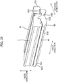
- the solvent cartridge 24 includes a solvent casing 24A, the first handle 24B, a second handle 24C, a cartridge guide 24D1, and a cartridge guide 24D2.
- the operation panel 29 is positioned on the upper surface of the main casing 2.
- the operation panel 29 is positioned away from the discharge tray 11 in the first direction.
- the operation panel 29 is positioned above the solvent cartridge 24 in a state where the solvent cartridge 24 is attached to the main casing 2.
- the operation panel 29 is electrically connected to the first circuit board 27.
- the operation panel 29 is operated by the user.
- the solvent cartridge 24 is positioned away from the developing cartridge 7 in the first direction.
- increasing in size of the image forming apparatus 1 in the up-down direction can be restrained in comparison with a configuration in which the developing cartridge 7 and the solvent cartridge 24 are arranged in the up-down direction in a state where the developing cartridge 7 and the solvent cartridge 24 are attached to the main casing 2.
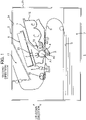
- the first opening 2A and the second opening 2B are positioned at the one end portion E1 in the second direction of the main casing 2, as illustrated in Fig. 2 .
- the developing cartridge 7 is attachable to the main casing 2 through the first opening 2A in the second direction.
- the solvent cartridge 24 is attachable to the main casing 2 through the second opening 2B in the second direction.
- replacement of the developing cartridge 7 and the solvent cartridge 24 can be performed at one side in the second direction of the main casing 2.
- the replacement of the solvent cartridge 24 can be performed at the one side of the main casing 2 which is the same as the side in which the replacement of the developing cartridge 7 is performed.
- the second cover 22 makes contact with the solvent cartridge 24 in a state where the solvent cartridge 24 is attached to the main casing 2 and the second cover 22 is at the second closed position.
- the second cover 22 has the guide 22B1 and the guide 22B2 as illustrated in Fig. 2 .
- the guide 22B1 and the guide 22B2 guide the solvent cartridge 24 when attaching the solvent cartridge 24 to the main casing 2 while the second cover 22 is at the second open position.
- the solvent cartridge 24 can be guided toward the main casing 2 by making use of the second cover 22 positioned at the second open position.
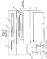
- the main casing 2 has the guide 2D1 and the guide 2D2 as illustrated in Figs. 2 and 4 .
- the guide 2D1 and the guide 2D2 guide the solvent cartridge 24 during the attachment of the solvent cartridge 24 to the main casing 2.
- the solvent cartridge 24 can be guided inside the main casing 2.
- replacement of the sheet cassette 3 can be performed at the one side of the main casing 2 in the second direction.
- the replacement of the sheet cassette 3 can be performed at the side the same as the side in which the replacement of the developing cartridge 7 and the solvent cartridge 24 is performed with respect to the main casing 2.
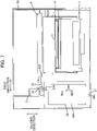
- the first circuit board 27 is electrically connected to the pump 26 that pumps the solvent from the solvent cartridge 24 to the applicator 9, as illustrated in Fig. 7 .
- the first circuit board 27 and the solvent cartridge 24 are arranged in the second direction in a state where the solvent cartridge 24 is attached to the main casing 2.
- the first circuit board 27 is positioned close to the solvent cartridge 24 in the first direction.
- the developing cartridge 7 is positioned between the solvent cartridge 24 and the second circuit board 28 in the first direction, as illustrated in Fig. 7 .
- the second circuit board 28 is positioned on the opposite side of the developing cartridge 7 from the solvent cartridge 24 in the first direction.
- the solvent cartridge 24 can be suppressed from being electrified due to electric power supplied from the second circuit board 28 to the charging unit 5 and the applicator 9.
- the solvent cartridge 24 is attachable to the main casing 2 in a state where the solvent cartridge 24 is mounted on the second cover 22.
- the solvent cartridge 24 is attachable to the main casing 2 in the first direction.
- At least a portion of the solvent cartridge 24 is juxtaposed with the developing cartridge 7 in the first direction in a state where the developing cartridge 7 and the solvent cartridge 24 are attached to the main casing 2.
- the solvent cartridge 24 is positioned away from the developing cartridge 7 in the first direction in a state where the developing cartridge 7 and the solvent cartridge 24 are attached to the main casing 2.
- the second opening 2B may be positioned at an upper end portion of the main casing.
- the solvent cartridge 24 is attachable to the main casing 2 in the up-down direction.
- the solvent cartridge 24 is positioned away from the developing cartridge 7 in the first direction in a state where the developing cartridge 7 and the solvent cartridge 24 are attached to the main casing 2.
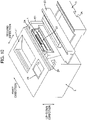
- the image forming apparatus 1 may include a single cover 20 instead of the first cover 21 and the second cover 22 as illustrated in Fig. 10 .
- the cover 20 is movable between a closed position (not illustrated) and an open position (see Fig. 10 ).
- the cover 20 closes the first opening 2A and the second opening 2B in a state where the cover 20 is at the closed position.
- the first opening 2A and the second opening 2B are opened in a state where the cover 20 is at the open position.
- the replacement of the developing cartridge 7 and the solvent cartridge 24 can be performed easily even in a case where the replacement of both the developing cartridge 7 and the solvent cartridge 24 is desired.
- the solvent cartridge 24 may be positioned on the opposite side of the first circuit board 27 from the developing cartridge 7 in the first direction in a state where the developing cartridge 7 and the solvent cartridge 24 are attached to the main casing 2.
- the second circuit board 28 may be positioned downward of the developing cartridge 7 in a state where the developing cartridge 7 and the solvent cartridge 24 are attached to the main casing 2.
- the sheet cassette 3 may be installed in the main casing 2 so as not to be attachable to or detachable from the main casing 2.
- the sheet cassette 3 includes a portion for accommodating therein the sheet S and movable through the third opening 2C between an interior position in which the portion is positioned inside the main casing 2 and an exterior position in which the portion is positioned outside the main casing 2.
- the guide 2D1 and the guide 2D2, and the guide 22B1 and the guide 22B2 may be grooves.
- the cartridge guide 24D1 and the cartridge guide 24D2 may be ribs.
- the developing cartridge 7 and the drum cartridge 23 may be detachably attachable to the main casing 2 independently of each other.
- the developing cartridge 7 may be integral with the drum cartridge 23.
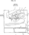
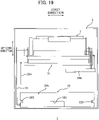
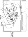
- An image forming apparatus 1 includes a main casing 2 (see Fig. 14 ), a cover 30 (see Fig. 14 ), a drum cartridge 31 (see Fig. 13 ), a solvent cartridge 32 (see Fig. 13 ), a supply pipe 33 (see Fig. 15 ), a pump 34 (see Fig. 15 ), a first circuit board 39A (see Fig. 15 ), and a second circuit board 39B (see Fig. 15 ).
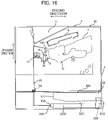
- the main casing 2 has a first opening 35, a second opening 36, and a third opening 37.
- the main casing 2 includes a guide 38A (see Fig. 15 ) and a guide 38B (see Fig. 15 ).
- the first opening 35 is positioned at one end portion E1 in the second direction of the main casing 2.
- the second direction crosses the first direction.
- the developing cartridge 7 passes through the first opening 35 when the developing cartridge 7 is attached to the main casing 2.
- the drum cartridge 31 (see Fig. 13 ) is also attachable to the main casing 2 through the first opening 35.
- the developing cartridge 7 and the drum cartridge 31 are attachable to the main casing 2 in the second direction. Note that the developing cartridge 7 and the drum cartridge 31 those attached to the main casing 2 are detachable from the main casing 2 through the first opening 35.
- the second opening 36 is positioned at the one end portion E1 in the second direction of the main casing 2.
- the second opening 36 is positioned downward and away from the first opening 35.
- the second opening 36 is positioned on the opposite side of the third opening 37 from the first opening 35.
- the solvent cartridge 32 passes through the second opening 36 when the solvent cartridge 32 is attached to the main casing 2. That is, the drum cartridge 31 and the developing cartridge 7 are attached to the main casing 2 through the first opening 35 whereas the solvent cartridge 32 is attached to the main casing 2 through the second opening 36 positioned away from the first opening 35.
- the solvent cartridge 32 is attachable to the main casing 2 independently of the drum cartridge 31 and the developing cartridge 7.
- the drum cartridge 31 is attachable to the main casing 2 independently of the solvent cartridge 32.
- the solvent cartridge 32 is attachable to the main casing 2 in the second direction. Note that the solvent cartridge 32 attached to the main casing 2 is detachable from the main casing 2 through the second opening 36.
- the third opening 37 is positioned at the one end portion E1 in the second direction of the main casing 2.
- the sheet cassette 3 is attachable to the main casing 2 through the third opening 37.
- the sheet cassette 3 is attachable to the main casing 2 in the second direction. Note that the sheet cassette 3 attached to the main casing 2 is detachable from the main casing 2 through the third opening 37.
- the sheet cassette 3 is detachably attachable to the main casing 2 independently of the solvent cartridge 32. In other words, the solvent cartridge 32 is detachably attachable to the main casing 2 independently of the sheet cassette 3.
- the third opening 37 is positioned between the first opening 35 and the second opening 2B in the up-down direction.
- the sheet cassette 3 is positioned below the developing cartridge 7 in a state where the sheet cassette 3 is attached to the main casing 2.
- the sheet cassette 3 is positioned between the developing cartridge 7 and the solvent cartridge 32 in the up-down direction in a state where the developing cartridge 7, the solvent cartridge 32, and the sheet cassette 3 are attached to the main casing 2.
- the sheet cassette 3 includes the sheet handle 3A.
- the sheet handle 3A is positioned at the one end portion E1 in the second direction of the main casing 2 in a state where the sheet cassette 3 is attached to the main casing 2.
- the guide 38A is positioned inside the second opening 36.
- the guide 38A guides the solvent cartridge 32 when the solvent cartridge 32 is attached to the main casing 2.
- the guide 38A extends in the second direction.
- the guide 38A is a rib extending in the first direction.
- the guide 38B is positioned inside the second opening 36.
- the guide 38B is positioned away from the guide 38A in the first direction.
- the guide 38B guides the solvent cartridge 32 when the solvent cartridge 32 is attached to the main casing 2.
- the guide 38B extends in the second direction.
- the guide 38B is a rib extending in the first direction.
- the cover 30 is positioned at the one end portion E1 in the second direction of the main casing 2.
- the cover 30 is movable between a closed position (see Fig. 13 ) and an open position (see Fig. 14 ).
- the cover 30 is pivotally movable about a cover axis 30A.
- the cover axis 30A extends in the first direction.
- the cover 30 extends in the up-down direction in a state where the cover 30 is at the closed position.
- the cover 30 closes the first opening 35 in a state where the cover 30 is at the closed position.
- the cover 30 extends in the second direction in a state where the cover 30 is at the open position.
- the first opening 35 is opened when the cover 30 is at the open position.
- the drum cartridge 31 is attachable to the main casing 2.
- the drum cartridge 31 is attachable to the image forming apparatus 1.
- the drum cartridge 31 includes the photosensitive drum 4, the charging unit 5, and the transfer unit 8.
- the main casing 2 may include the transfer unit 8.
- the developing cartridge 7 is detachably attachable to the drum cartridge 31.
- the developing cartridge 7 is attachable to the main casing 2 in a state where the developing cartridge 7 is attached to the drum cartridge 31.
- the solvent cartridge 32 is positioned below the developing cartridge 7 in a state where the developing cartridge 7 and the solvent cartridge 32 are attached to the main casing 2. This arrangement can suppress increasing in size of the image forming apparatus 1 in the first direction. At least a portion of the exposure unit 6 is positioned upward of the developing cartridge 7 and the solvent cartridge 32 in a state where the developing cartridge 7 and the solvent cartridge 32 are attached to the main casing 2.
- the solvent cartridge 32 is positioned below the sheet cassette 3 in a state where the solvent cartridge 32 and the sheet cassette 3 are attached to the main casing 2.
- the solvent cartridge 32 is positioned downward of the applicator 9 in a state where the solvent cartridge 32 is attached to the main casing 2.
- the solvent cartridge 32 includes a solvent casing 32A, a cartridge handle 32B, a cartridge guide 32C, and a cartridge guide 32D.
- the solvent casing 32A can accommodate therein solvent.
- the solvent cartridge 32 can accommodate therein solvent.
- the solvent dissolves toner.
- the solvent casing 32A extends in the second direction in a state where the solvent cartridge 32 is attached to the main casing 2.
- the solvent casing 32A has a discharge opening 32E.
- the discharge opening 32E allows the solvent to be discharged therethrough from the solvent casing 32A to the supply pipe 33.
- the discharge opening 32E is positioned at one end portion E11 in the second direction of the solvent casing 32A.
- the cartridge handle 32B is positioned at another end portion E12 in the second direction of the solvent casing 32A in a state where the solvent cartridge 32 is attached to the main casing 2.
- the user moves the solvent cartridge 32 in the second direction when attaching the solvent cartridge 32 to the main casing 2 and when detaching the solvent cartridge 32 from the main casing 2.
- the cartridge handle 32B is grasped by the user.
- the cartridge guide 32C is positioned on a side surface 32S1 in the first direction of the solvent casing 32A.
- the cartridge guide 32C is in a form of a groove.
- the guide 38A of the main casing 2 is fitted into the cartridge guide 32C when the solvent cartridge 32 is attached to the main casing 2.
- the cartridge guide 32C is guided by the guide 38A. Accordingly, the solvent cartridge 32 is guided by the guide 38A in the second direction.
- the cartridge guide 32D is positioned on a side surface 32S2 in the first direction of the solvent casing 32A.
- the side surface 32S2 is positioned away from the side surface 32S1 in the first direction.
- the cartridge guide 32D is in a form of a groove.
- the guide 38B of the main casing 2 is fitted into the cartridge guide 32D when the solvent cartridge 32 is attached to the main casing 2.
- the cartridge guide 32D is guided by the guide 38B.
- the solvent cartridge 32 is guided by the guide 38B in the second direction.
- the supply pipe 33 has one end portion 33A and another end portion 33B.
- the one end portion 33A is connected to the discharge opening 32E of the solvent cartridge 32 in a state where the solvent cartridge 32 is attached to the main casing 2.
- the other end portion 33B is positioned away from the one end portion 33A.
- the other end portion 33B is connected to the applicator casing 14 of the applicator 9.
- the pump 34 is positioned between the one end portion 33A and the other end portion 33B of the supply pipe 33.
- the pump 34 pumps the solvent from the solvent cartridge 32 to the applicator 9.
- the pump 34 is driven in a state where the solvent cartridge 32 is attached to the main casing 2, the solvent accommodated in the solvent cartridge 32 is introduced into the applicator casing 14 of the applicator 9 through the discharge opening 32E and the supply pipe 33.
- the pump 34 is a gear pump.
- the first circuit board 39A is juxtaposed with the applicator 9 in the first direction.
- the first circuit board 39A is electrically connected to the pump 34.
- the first circuit board 39A is a control circuit board.
- the first circuit board 39A controls the pump 34.
- the second circuit board 39B is positioned to be spaced apart from the first circuit board 39A in the first direction.
- the second circuit board 39B is positioned on the opposite side of the applicator 9 from the first circuit board 39A in the first direction. In other words, the applicator 9 is positioned between the first circuit board 39A and the second circuit board 39B in the first direction.
- the second circuit board 39B is electrically connected to the charging unit 5 and the transfer unit 8.
- the second circuit board 39B applies a voltage to the charging unit 5 and the transfer unit 8.
- the second circuit board 39B is electrically connected to the applicator 9.
- the second circuit board 39B supplies electric power to the applicator 9.
- the second circuit board 39B is electrically connected to the developing cartridge 7.
- the second circuit board 39B applies a voltage to the developing cartridge 7.
- the second circuit board 39B is electrically connected to the developing roller 13.
- the second circuit board 39B applies a voltage to the developing roller 13.
- the solvent cartridge 32 is positioned downward of the developing cartridge 7 in a state where the developing cartridge 7 and the solvent cartridge 32 are attached to the main casing 2.
- enlargement of the image forming apparatus 1 in the first direction can be restrained in comparison with a configuration where the developing cartridge 7 and the solvent cartridge 32 are arranged in the first direction in a state where the developing cartridge 7 and the solvent cartridge 32 are attached to the main casing 2.
- the first opening 35 and the second opening 36 are positioned at the one end portion E1 in the second direction of the main casing 2, as illustrated in Fig. 14 .
- the developing cartridge 7 is attachable to the main casing 2 through the first opening 35 in the second direction.
- the solvent cartridge 32 is attachable to the main casing 2 through the second opening 36 in the second direction.
- the replacement of the developing cartridge 7 and the solvent cartridge 32 can be performed at one side in the second direction of the main casing 2.
- the replacement of the solvent cartridge 32 can be performed at the side of the main casing 2 which is the same as the side in which the replacement of the developing cartridge 7 is performed.
- the developing cartridge 7 and the solvent cartridge 32 can be replaced easily.
- the sheet handle 3A of the sheet cassette 3 is positioned at the one end portion E1 in the second direction of the main casing 2 as illustrated in Fig. 14 .
- replacement of the sheet cassette 3 can be performed at the one side of the main casing 2 in the second direction.
- the replacement of the sheet cassette 3 can be performed at the side the same as the side in which the replacement of the developing cartridge 7 and the solvent cartridge 32 is performed with respect to the main casing 2.
- an image forming apparatus 1 includes the main casing 2 described above, a cover 40, a drum cartridge 41, a solvent cartridge 42, a supply pipe 43, and a pump 44.
- the main casing 2 has an opening 45.
- the main casing 2 has one end portion 2E1 and another end portion 2E2 in the second direction.
- the second direction crosses the first direction.
- the other end portion 2E2 is spaced apart from the one end portion 2E1 in the second direction.
- the applicator 9 is positioned at the one end portion 2E1 of the main casing 2.
- the opening 45 is positioned at the other end portion 2E2 in the second direction of the main casing 2.
- the developing cartridge 7 and the solvent cartridge 42 pass through the opening 45 when the developing cartridge 7 and the solvent cartridge 42 are attached to the main casing 2.
- the developing cartridge 7 and the solvent cartridge 42 are attachable to the main casing 2 in the second direction. Note that the developing cartridge 7 and the solvent cartridge 42 those attached to the main casing 2 are detachable from the main casing 2 through the opening 45.
- the cover 40 is positioned at the other end portion 2E2 in the second direction of the main casing 2.
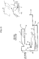
- the cover 40 is movable between a closed position (see Fig. 20 ) and an open position (see Fig. 21 ).
- the cover 40 is pivotally movable about a cover axis 40A.
- the cover axis 40A extends in the first direction.
- the cover 40 extends in the up-down direction in a state where the cover 40 is at the closed position.
- the cover 40 closes the opening 45 in a state where the cover 40 is at the closed position.
- the cover 40 extends in the second direction in a state where the cover 40 is at the open position.
- the opening 45 is opened in a state where the cover 40 is at the open position.
- the drum cartridge 41 is movable in the second direction through the opening 45 between an interior position (see Fig. 20 ) and an exterior position (see Fig. 21 ).
- the drum cartridge 41 is positioned inside the main casing 2 (see Fig. 20 ) in a state where the drum cartridge 41 is at the interior position.
- the drum cartridge 41 is positioned outside the main casing 2 (see Fig. 21 ) in a state where the drum cartridge 41 is at the exterior position.
- the drum cartridge 41 includes the photosensitive drum 4, the charging unit 5, and a drum frame 41A.
- the drum cartridge 41 may include the transfer unit 8.
- the main casing 2 includes the transfer unit 8.
- the transfer unit 8 can convey the sheet S in the second direction toward the applicator 9.
- the drum frame 41A extends in the second direction.
- the drum frame 41A supports the photosensitive drum 4.
- the drum frame 41A can support the developing cartridge 7 and the solvent cartridge 42.
- the drum cartridge 41 is movable in a state where the drum frame 41A supports the developing cartridge 7 and the solvent cartridge 42.
- the developing cartridge 7 is detachably attachable to the drum frame 41A.
- a state where the developing cartridge 7 is attached to the drum frame 41A denotes a state where the developing cartridge 7 is supported by a certain position of the drum frame 41A.
- the developing cartridge 7 may be movable relative to the drum frame 41A in a state where the developing cartridge 7 is attached to the drum frame 41A.
- the developing cartridge 7 is attached to the main casing 2 while the developing cartridge 7 is attached to the drum frame 41A and the drum cartridge 41 is at the interior position.
- the developing cartridge 7 is detachable from the drum frame 41A in a state where the drum cartridge 41 is at the exterior position, as indicated by an imaginary line in Fig. 21 .
- the solvent cartridge 42 is attached to the main casing 2 in a state where the solvent cartridge 42 is attached to the drum frame 41A and the drum cartridge 41 is at the interior position.
- the solvent cartridge 42 is detachable from the drum frame 41A in a state where the drum cartridge 41 is at the exterior position, as indicated by an imaginary line in Fig. 21 .
- the developing cartridge 7 since the developing cartridge 7 is positioned closer to the cover 40 than the solvent cartridge 42 is to the cover 40 in the second direction in a state where the developing cartridge 7 and the solvent cartridge 42 are attached to the main casing 2, the developing cartridge 7 can be replaced easily in a state where the cover 40 is at the open position (see Fig. 21 ). Further, this configuration can restrain the user's hands from getting dirty with solvent adhered to the solvent cartridge 42 during a process of attachment and detachment of the developing cartridge 7.
- the solvent cartridge 42 includes a solvent casing 42A.
- the solvent casing 42A can accommodate therein solvent.
- the solvent cartridge 42 can accommodate therein solvent.
- the solvent dissolves toner.
- the solvent casing 42A extends in the second direction in a state where the solvent cartridge 42 is attached to the main casing 2.
- the solvent casing 42A has a discharge opening 42B.
- the discharge opening 42B allows the solvent to be discharged therethrough from the solvent casing 42A to the supply pipe 43.
- the discharge opening 42B is positioned at one end portion E11 in the second direction of the solvent casing 42A.
- the solvent casing 42A has another end portion E12 positioned away from the one end portion E11 in the second direction.
- the one end portion E11 is positioned on the opposite side of the other end portion E 12 from the developing cartridge 7 in the second direction in a state where the developing cartridge 7 and the solvent cartridge 42 are attached to the main casing 2.
- the user's hands can be suppressed from getting dirty with the solvent adhered to the solvent cartridge 42 during a process of attachment and detachment of the developing cartridge 7.
- the drum cartridge 48 is detachably attachable to the main casing 46 in the third direction in a state where the cover 47 is at the open position. Note that the drum cartridge 48 attached to the main casing 46 is detachable from the main casing 46 through the opening 46A.
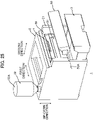
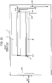
- the inlet port 55 allows solvent accommodated in the solvent cartridge 52 to be introduced into the main casing 2 therethrough.
- the inlet port 55 allows the solvent accommodated in the solvent cartridge 52 to be introduced into the supply pipe 53 (see Fig. 28 ) therethrough in a state where the solvent cartridge 52 is connected to the inlet port 55.
- the inlet port 55 is in communication with an internal space of the supply pipe 53 (see Fig. 28 ).
- the solvent casing 52A is positioned outside the main casing 2 in a state where the solvent cartridge 52 is connected to the inlet port 55.
- the solvent casing 52A is positioned upward of the main casing 2 in a state where the solvent cartridge 52 is connected to the inlet port 55.
- the solvent casing 52A extends in the up-down direction in a state where the solvent cartridge 52 is connected to the inlet port 55.
- the solvent casing 52A has a discharge opening 52E.
- the discharge opening 52E allows the solvent to be discharged therethrough from the solvent casing 52A to the supply pipe 53 (see Fig. 28 ).
- the discharge opening 52E is positioned at a lower end portion of the solvent casing 52A in a state where the solvent cartridge 52 is connected to the inlet port 55.
- the first circuit board 56 is positioned inside the main casing 2 (see Fig. 24 ).
- the first circuit board 56 extends in the second direction.
- the first circuit board 56 is positioned juxtaposed with the applicator 9 in the first direction.
- the first circuit board 56 is electrically connected to the pump 54.
- the first circuit board 56 is a control circuit board.
- the first circuit board 56 controls the pump 54.
- the replenishment of the main casing 2 with the solvent accommodated in the solvent cartridge 52 can be performed from an outside of the main casing 2 through the inlet port 55.
- the applicator 9 can be replenished with the solvent (see Fig. 28 ).
- the image forming apparatus 1 can be made compact in comparison with a configuration where the solvent cartridge 52 is accommodated inside the main casing 2.
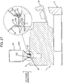
- first thread 52C of the solvent cartridge 52 is in threading engagement with the second thread 58 of the main casing 2 in a state where the solvent cartridge 52 is connected to the main casing 2, as illustrated in Fig. 17 . Therefore, displacement of the discharge opening 52E of the solvent cartridge 52 from the inlet port 55 during the replenishment for the solvent can be suppressed. As a result, the replenishment of the main casing 2 with the solvent from the solvent cartridge 52 can be performed stably.
- an image forming apparatus 1 includes a drum cartridge 60.
- the drum cartridge 60 is detachably attachable to the main casing 2.
- the drum cartridge 60 is detachably attachable to the image forming apparatus 1.
- the drum cartridge 60 includes the photosensitive drum 4, the charging unit 5, the transfer unit 8, a drum frame 61 (see Fig. 31 ), a charge electrode 62A (see Fig. 32 ), a charge electrode 62B (see Fig. 32 ), a transfer electrode 62C (see Fig. 32 ), and a sheet conveying roller 63 (see Fig. 29 ).
- the main casing 2 may include the transfer unit 8 and the sheet conveying roller 63.
- the drum frame 61 extends in the first direction and the second direction.
- the second direction crosses the first direction.
- the second direction is perpendicular to the first direction. More preferably, the second direction is perpendicular to both the first direction and the third direction in a state where the drum cartridge 60 is attached to the main casing 2.
- the drum frame 61 has one end portion E21 and another end portion E22 in the first direction.
- the drum frame 61 has one end portion E31 and another end portion E32 in the second direction.
- the developing cartridge 7 is positioned at the other end portion E32 in the second direction of the drum frame 61 in a state where the developing cartridge 7 is attached to the drum frame 61.
- the drum frame 61 includes a side plate 64A, a side plate 64B, a solvent casing 65, a waste solvent casing 66, and a tube 67.
- the drum cartridge 60 includes the solvent casing 65, the waste solvent casing 66, and the tube 67.
- the side plate 64A is positioned at the one end portion E21 in the first direction of the drum frame 61.
- the side plate 64A extends in the second direction.
- the solvent casing 65 is positioned at the one end portion E31 in the second direction of the drum frame 61.
- the developing cartridge 7 is attached to the drum frame 61
- at least a portion of the solvent casing 65 is positioned on the opposite side of the photosensitive drum 4 from the developing cartridge 7 in the second direction.
- the photosensitive drum 4 is positioned between the solvent casing 65 and the developing cartridge 7 in the second direction.
- at least a portion of the solvent casing 65 is positioned between the photosensitive drum 4 and the applicator 9 in the second direction.
- the discharge opening 651 is positioned at the one end portion in the first direction of the solvent casing 65.
- the discharge opening 651 allows the solvent accommodated in the solvent casing 65 to be discharged therethrough.
- the tube 67 is positioned at the one end portion E21 in the first direction of the drum frame 61.
- the tube 67 extends in the second direction.
- the tube 67 has one end portion in the second direction connected to the waste solvent casing 66.
- the charge electrode 62A, the charge electrode 62B, and the transfer electrode 62C are mounted on the side plate 64B.
- the charge electrode 62A and the charge electrode 62B are electrically connected to the charging unit 5.
- the charging unit 5 includes a wire 5A (see Fig. 29 ), and a grid 5B (see Fig. 29 ).
- the charge electrode 62A is electrically connected to the wire 5A.
- the charge electrode 62B is electrically connected to the grid 5B.
- the transfer electrode 62C is electrically connected to the transfer unit 8.
- the sheet conveying roller 63 conveys the sheet S toward the photosensitive drum 4 and the transfer unit 8 in a state where the drum cartridge 60 is attached to the main casing 2. Specifically, the sheet conveying roller 63 makes contact with a sheet conveying roller 70 of the main casing 2 in a state where the drum cartridge 60 is attached to the main casing 2. The sheet conveying roller 70 of the main casing 2 will be described later.
- the sheet conveying roller 63 can convey the sheet S in cooperation with the sheet conveying roller 70 in a state where the drum cartridge 60 is attached to the main casing 2. Note that the sheet conveying roller 63 is in separation from the sheet conveying roller 70 in a state where the drum cartridge 60 is detached from the main casing 2, as illustrated in Fig. 30 .
- the main casing 2 includes a supply pipe 68A (see Fig. 29 ), a pump 68B (see Fig. 29 ), a waste solvent tray 68C (see Fig. 29 ), a discharge pipe 68D (see Fig. 29 ), a first circuit board 69A (see Fig. 33 ), a second circuit board 69B (see Fig. 33 ), and the sheet conveying roller 70 (see Fig. 29 ).
- the supply pipe 68A supplies solvent to the applicator 9.
- the supply pipe 68A has one end portion and another end portion.
- the one end portion of the supply pipe 68A is connected to the discharge opening 651 (see Fig. 31 ) of the drum cartridge 60 in a state where the drum cartridge 60 is attached to the main casing 2.
- the other end portion of the supply pipe 68A is positioned away from the one end portion of the supply pipe 68A.
- the other end portion of the supply pipe 68A is connected to the applicator casing 14 of the applicator 9.
- the pump 68B is positioned between the one end portion and the other end portion of the supply pipe 68A.
- the pump 68B pumps the solvent from the solvent casing 65 to the applicator 9.
- the pump 68B is driven in a state where the drum cartridge 60 is attached to the main casing 2
- the solvent accommodated in the solvent casing 65 is introduced into the applicator casing 14 of the applicator 9 through the discharge opening 651 and the supply pipe 68A.
- the solvent entered the applicator casing 14 is sprayed through the nozzles 15 onto the toner that has been transferred to the sheet S from the photosensitive drum 4.
- the sprayed solvent dissolves the toner on the sheet S.
- the pump 68B is a gear pump.
- the waste solvent tray 68C is positioned below the applicator 9.
- the waste solvent tray 68C is positioned to be spaced apart from the applicator 9.
- the sheet S on which toner has been transferred passes through a space between the applicator 9 and the waste solvent tray 68C.
- the waste solvent tray 68C accommodates therein the waste solvent.
- the waste solvent is solvent discharged from the applicator 9 but not applied to the sheet S. For example, in a case where printing operations are continuously performed on a first sheet S and a second sheet S subsequent to the first sheet S, solvent discharged from the applicator 9 to an interval between the first sheet S and the second sheet S is not applied to either of the first sheet S and the second sheet S, but is accommodated in the waste solvent tray 68C as the waste solvent.
- the discharge pipe 68D discharges the waste solvent from the applicator 9.
- the discharge pipe 68D has one end portion and another end portion.
- the one end portion of the discharge pipe 68D is connected to the other end portion in the second direction of the tube 67 (see Fig. 31 ).
- the other end portion of the discharge pipe 68D is positioned away from the one end portion of the discharge pipe 68D.
- the other end portion of the discharge pipe 68D is connected to the waste solvent tray 68C.
- the waste solvent in the waste solvent tray 68C enters the waste solvent casing 66 through the discharge pipe 68D and the tube 67.
- the first circuit board 69A is positioned at one end portion in the first direction of the main casing 2. In a state where the drum cartridge 60 is attached to the main casing 2, the first circuit board 69A is positioned to be spaced apart from the drum cartridge 60 in the first direction. In a state where the drum cartridge 60 is attached to the main casing 2, the first circuit board 69A is positioned on the opposite side of the one end portion E21 of the drum frame 61 from the other end portion E22 of the drum frame 61 in the first direction.
- the first circuit board 69A is electrically connected to the pump 68B (see Fig. 29 ). Specifically, the first circuit board 69A is a control circuit board.
- the first circuit board 69A controls the pump 68B.
- the second circuit board 69B is positioned to be spaced apart from the first circuit board 69A in the first direction.
- the second circuit board 69B In a state where the drum cartridge 60 is attached to the main casing 2, the second circuit board 69B is positioned on the opposite side of the drum cartridge 60 from the first circuit board 69A in the first direction. In other words, the drum cartridge 60 is positioned between the first circuit board 69A and the second circuit board 69B in the first direction.
- the second circuit board 69B is electrically connected to the charge electrode 62A, the charge electrode 62B, and the transfer electrode 62C.
- the sheet conveying roller 70 is positioned below the sheet conveying roller 63 in a state where the drum cartridge 60 is attached to the main casing 2.
- the sheet conveying roller 70 makes contact with the sheet conveying roller 63 in a state where the drum cartridge 60 is attached to the main casing 2.
- the sheet conveying roller 70 can convey sheet S in cooperation with the sheet conveying roller 63 in a state where the drum cartridge 60 is attached to the main casing 2.
- the supply pipe 68A for supplying the solvent from the solvent casing 65 to the applicator 9 can be shortened, thereby restraining complication of a piping arrangement from the solvent casing 65 to the applicator 9.
- enlargement of a capacity of the solvent casing 65 can be achieved by making use of a space between the photosensitive drum 4 and the applicator 9.
- the charge electrode 62A is positioned on the opposite side of the solvent casing 65 in the first direction from the tube 67 (see Fig. 31 ) through which the waste solvent flows.
- the charge electrode 62A can be restrained from getting dirty with the waste solvent even if leakage of the waste solvent from the tube 67 occurs.
- the transfer electrode 62C is positioned on the opposite side of the solvent casing 65 in the first direction from the tube 67 (see Fig. 31 ) through which the waste solvent flows.
- the transfer electrode 62C can be restrained from getting dirty with the waste solvent even if leakage of the waste solvent from the tube 67 occurs.
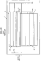
- a developing cartridge 7 according to the seventh embodiment extends in the first direction.
- the developing cartridge 7 has one end portion E41 and another end portion E42 in the first direction.
- the developing cartridge 7 includes a casing 71, an agitator 72 (see Fig. 34 ), a developing electrode 73, a storage medium 74, and a plurality of electrical contact surfaces 75.
- the casing 71 extends in the first direction and the second direction.
- the second direction crosses the first direction.
- the second direction is perpendicular to the first direction.
- the second direction is a direction defined by connecting the developing axis A2 (see Fig. 34 ) and an agitator axis A5 to each other.
- the agitator axis A5 will be described later.
- the casing 71 has one end portion E51 and another end portion E52 in the second direction.
- the developing roller 13 is positioned at the one end portion E51 in the second direction of the casing 71.
- the casing 71 includes the toner casing 12 described above, a solvent casing 71A, and a tube 71B.
- At least a portion of the toner casing 12 is positioned between the developing roller 13 and the solvent casing 71A in the second direction. In a state where the developing cartridge 7 is attached to the main casing 2, the toner casing 12 is positioned on the opposite side of the developing roller 13 from the photosensitive drum 4 in the second direction.
- the solvent casing 71A is positioned at the other end portion E52 in the second direction of the casing 71. In a state where the developing cartridge 7 is attached to the main casing 2, the solvent casing 71A is positioned on the opposite side of the toner casing 12 from the developing roller 13 in the second direction.
- the solvent casing 71A can accommodate therein solvent.
- the tube 71B is positioned at one end portion in the third direction of the casing 71.
- the third direction crosses the first direction and the second direction.
- the third direction is parallel to the up-down direction in a state where the developing cartridge 7 is attached to the main casing 2.
- the tube 71B extends in the second direction.
- the tube 71B has one end portion in the second direction in communication with the solvent casing 71A.
- the tube 71B has a discharge opening 71C.
- the discharge opening 71C is positioned at another end portion in the second direction of the tube 71B.
- the discharge opening 71C is positioned at the one end portion E51 in the second direction of the casing 71.
- the discharge opening 71C is positioned on the opposite side of the toner casing 12 from the solvent casing 71A in the second direction.
- the discharge opening 71C is positioned at a lower end portion of the casing 71.
- the solvent accommodated in the solvent casing 71A flows the tube 71B and is discharged through the discharge opening 71C.
- the discharge opening 71C allows the solvent accommodated in the solvent casing 71A to be discharged therethrough.
- the agitator 72 is positioned inside the toner casing 12.
- the agitator 72 is positioned between the developing roller 13 and the solvent casing 71A in the second direction.
- the agitator 72 is rotatable about the agitator axis A5.
- the agitator 72 makes rotations to agitate the toner in the toner casing 12.
- the agitator axis A5 extends in the first direction.
- the developing electrode 73 is positioned at the other end portion E42 in the first direction of the developing cartridge 7.
- the developing electrode 73 is mounted on the other end portion in the first direction of the casing 71.
- the developing electrode 73 is positioned away from the tube 71B and the discharge opening 71C in the first direction.
- the developing electrode 73 is electrically connected to the developing roller 13.
- the storage medium 74 is positioned at the other end portion E42 in the first direction of the developing cartridge 7.
- the storage medium 74 is mounted on the other end portion in the first direction of the casing 71.
- the storage medium 74 is positioned away from the tube 71B and the discharge opening 71C in the first direction.
- the storage medium 74 is an IC chip.
- the storage medium 74 has a flat plate shape.
- the storage medium 74 stores therein information related to the developing cartridge 7.
- Data related to the developing cartridge 7 is, for example, data indicative of whether the developing cartridge 7 is a new cartridge or an old cartridge, and data indicative of the number of sheets (or dot counts) printable using the developing cartridge 7.
- the plurality of electrical contact surfaces 75 are positioned on a surface of the storage medium 74.
- the storage medium 74 has the electrical contact surfaces 75.
- the plurality of electrical contact surfaces 75 are positioned at the other end portion E42 in the first direction of the developing cartridge 7.
- the plurality of electrical contact surfaces 75 are positioned away from the tube 71B and the discharge opening 71C in the first direction.
- the plurality of electrical contact surfaces 75 are electrically connected to the storage medium 74.
- the plurality of electrical contact surfaces 75 may be positioned away from the storage medium 74. In a case where the plurality of electrical contact surfaces 75 are positioned away from the storage medium 74, each of the electrical contact surfaces 75 is electrically connected to the storage medium 74 through a wiring.
- a single electrical contact surface 75 may be used.
- the image forming apparatus 1 includes a drum cartridge 78.
- the developing cartridge 7 is detachably attachable to the main casing 2 in a state where the developing cartridge 7 is attached to the drum cartridge 78.
- the drum cartridge 78 will be described below.
- the drum cartridge 78 is detachably attachable to the main casing 2. In other words, the drum cartridge 78 is detachably attachable to the image forming apparatus 1.
- the drum cartridge 78 includes the photosensitive drum 4 described above, the charging unit 5, the transfer unit 8, and a drum frame 78A.
- the drum frame 78A supports the photosensitive drum 4, the charging unit 5, and the transfer unit 8.
- the photosensitive drum 4 is positioned at one end portion in the second direction of the drum frame 78A.
- the developing cartridge 7 is detachably attachable to the drum frame 78A. In other words, the developing cartridge 7 is detachably attachable to the drum cartridge 78.
- the developing cartridge 7 is positioned at another end portion in the second direction of the drum frame 78A in a state where the developing cartridge 7 is attached to the drum frame 78A.
- the main casing 2 includes a supply pipe 76, and a pump 77.
- the supply pipe 76 supplies the solvent to the applicator 9.
- the supply pipe 76 has one end portion and another end portion. In a state where the developing cartridge 7 is attached to the main casing 2, the one end portion of the supply pipe 76 is connected to the tube 71B of the developing cartridge 7. In other words, in a state where the developing cartridge 7 is attached to the image forming apparatus 1, the supply pipe 76 is connected to the tube 71B positioned at the one end portion in the first direction of the developing cartridge 7. Hence, in a state where the developing cartridge 7 is attached to the image forming apparatus 1, the solvent casing 71A is connected to the supply pipe 76 of the image forming apparatus 1 through the tube 71B. The other end portion of the supply pipe 76 is positioned away from the one end portion of the supply pipe 76. The other end portion of the supply pipe 76 is connected to the applicator casing 14 of the applicator 9.
- the pump 77 is positioned between the one end portion and the other end portion of the supply pipe 76.
- the pump 77 pumps the solvent to the applicator 9.
- the solvent accommodated in the developing cartridge 7 is introduced into the applicator casing 14 of the applicator 9 through the tube 71B, the discharge opening 71C, and the supply pipe 76.
- the solvent entered the applicator casing 14 is sprayed through the nozzles 15 onto the toner that has been transferred to the sheet S from the photosensitive drum 4.
- the sprayed solvent dissolves the toner on the sheet S.
- the pump 77 is a gear pump.
- the developing electrode 73 can be restrained from getting dirty with the solvent even if the solvent is leaked from the supply pipe 76.
- the electrical contact surfaces 75 can be restrained from getting dirty with the solvent even if leakage of the solvent from the supply pipe 76 occurs.
- the supply pipe 78B is positioned at one end portion in the first direction of the drum cartridge 78.
- the drum frame 78A supports the supply pipe 78B.
- the supply pipe 78B In a state where the drum cartridge 78 is attached to the main casing 2, the supply pipe 78B is positioned upward of the photosensitive drum 4.
- one end portion of the supply pipe 78B In a state where the developing cartridge 7 is attached to the drum cartridge 78, one end portion of the supply pipe 78B is connected to the solvent casing 71A.
- the solvent casing 71A is connected to the supply pipe 78B of the drum cartridge 78 in a state where the developing cartridge 7 to the drum cartridge 78.
- Another end portion of the supply pipe 78B is connected to the applicator casing 14 of the applicator 9 in a state where the drum cartridge 78 is attached to the main casing 2, thereby allowing the solvent accommodated in the solvent casing 71A to be supplied to the applicator 9 through the supply pipe 78B.
- the supply pipe 78B may be positioned downward of the photosensitive drum 4 in a state where the drum cartridge 78 is attached to the main casing 2.
- the drum cartridge 78 may be dispensed with in the image forming apparatus 1.
- the photosensitive drum 4, the charging unit 5, and the transfer unit 8 are fixed to the main casing 2.
- the developing cartridge 7 is detachably attachable to the main casing 2.
- the image forming apparatus 1 may include a first circuit board 79A and a second circuit board 79B.
- the first circuit board 79A is positioned at one end portion in the first direction of the main casing 2. In a state where the developing cartridge 7 is attached to the main casing 2, the first circuit board 79A is positioned to be spaced apart from the developing cartridge 7 in the first direction. In a state where the developing cartridge 7 is attached to the main casing 2, the first circuit board 79A is positioned on the opposite side of the one end portion E41 of the developing cartridge 7 from the other end portion E42 of the developing cartridge 7 in the first direction.
- the first circuit board 79A is electrically connected to the pump 77 (see Fig. 34 ). Specifically, the first circuit board 79A is a control circuit board. The first circuit board 79A controls the pump 77.
- the second circuit board 79B is positioned to be spaced apart from the first circuit board 79A in the first direction. In a state where the developing cartridge 7 is attached to the main casing 2, the second circuit board 79B is positioned on the opposite side of the developing cartridge 7 from the first circuit board 79A in the first direction. In other words, the developing cartridge 7 is positioned between the first circuit board 79A and the second circuit board 79B in the first direction. In a state where the developing cartridge 7 is attached to the main casing 2, the second circuit board 79B is electrically connected to the developing electrode 73 (see Fig. 35 ). The second circuit board 79B applies a voltage to the developing roller 13.
- the second circuit board 79B is electrically connected to an electrode (not illustrated) of the drum cartridge 78.
- the second circuit board 79B applies a voltage to the charging unit 5.
- the second circuit board 79B is electrically connected to the applicator 9.
- the second circuit board 79B supplies electric power to the applicator 9.
- the second circuit board 79B is electrically connected to the electrical contact surfaces 75 (see Fig. 35 ).
- the second circuit board 79B supplies electric power to the storage medium 74.
Landscapes
- Physics & Mathematics (AREA)
- General Physics & Mathematics (AREA)
- Engineering & Computer Science (AREA)
- Computer Vision & Pattern Recognition (AREA)
- Electrophotography Configuration And Component (AREA)
- Fixing For Electrophotography (AREA)
Applications Claiming Priority (2)
| Application Number | Priority Date | Filing Date | Title |
|---|---|---|---|
| JP2019180540A JP2021056414A (ja) | 2019-09-30 | 2019-09-30 | 画像形成装置、ドラムカートリッジおよび現像カートリッジ |
| PCT/JP2020/035454 WO2021065567A1 (fr) | 2019-09-30 | 2020-09-18 | Dispositif de formation d'image, cartouche de tambour et cartouche de développement |
Publications (3)
| Publication Number | Publication Date |
|---|---|
| EP4040236A1 true EP4040236A1 (fr) | 2022-08-10 |
| EP4040236A4 EP4040236A4 (fr) | 2023-08-02 |
| EP4040236B1 EP4040236B1 (fr) | 2025-08-20 |
Family
ID=75271340
Family Applications (1)
| Application Number | Title | Priority Date | Filing Date |
|---|---|---|---|
| EP20872846.9A Active EP4040236B1 (fr) | 2019-09-30 | 2020-09-18 | Appareil de formation d'images, cartouche de tambour et cartouche de développement |
Country Status (4)
| Country | Link |
|---|---|
| US (1) | US11886129B2 (fr) |
| EP (1) | EP4040236B1 (fr) |
| JP (1) | JP2021056414A (fr) |
| WO (1) | WO2021065567A1 (fr) |
Families Citing this family (1)
| Publication number | Priority date | Publication date | Assignee | Title |
|---|---|---|---|---|
| JP2025135404A (ja) | 2024-03-05 | 2025-09-18 | 富士フイルム株式会社 | 情報処理装置、放射線画像撮影システム、情報処理方法及びプログラム |
Family Cites Families (15)
| Publication number | Priority date | Publication date | Assignee | Title |
|---|---|---|---|---|
| CN100403186C (zh) * | 2001-12-18 | 2008-07-16 | 株式会社理光 | 图像形成装置,带组件及图像形成系统 |
| EP1347344A3 (fr) * | 2002-03-20 | 2007-10-24 | Seiko Epson Corporation | Unité pour support d'image et appareil de formation d'images |
| JP4185742B2 (ja) * | 2002-09-20 | 2008-11-26 | 株式会社リコー | 画像形成装置 |
| DE10246901C1 (de) * | 2002-10-08 | 2003-12-18 | Oce Printing Systems Gmbh | Einrichtung und Verfahren zum Fixieren eines Tonerbildes durch Lösemitteldampf unter Reduzierung des Lösemittelaustrages |
| JP2004333866A (ja) * | 2003-05-08 | 2004-11-25 | Ricoh Co Ltd | 画像形成装置 |
| JP4393951B2 (ja) * | 2004-09-07 | 2010-01-06 | シャープ株式会社 | トナー定着液、トナー定着方法、トナー定着装置および画像形成装置 |
| JP2006293169A (ja) * | 2005-04-13 | 2006-10-26 | Sharp Corp | 画像形成装置 |
| JP2007155793A (ja) * | 2005-11-30 | 2007-06-21 | Brother Ind Ltd | 画像形成装置 |
| JP4224076B2 (ja) * | 2006-04-03 | 2009-02-12 | シャープ株式会社 | 画像形成装置 |
| JP4863946B2 (ja) | 2007-07-19 | 2012-01-25 | 株式会社リコー | 交換ユニット、画像形成装置、および画像形成装置の交換ユニット取り付け方法 |
| JP2009069256A (ja) * | 2007-09-11 | 2009-04-02 | Ricoh Co Ltd | 定着液の定温保持装置、および画像形成装置 |
| JP5065181B2 (ja) * | 2008-06-30 | 2012-10-31 | 株式会社リコー | 定着液を用いた定着装置及び画像形成装置 |
| WO2017057684A1 (fr) * | 2015-09-30 | 2017-04-06 | ブラザー工業株式会社 | Dispositif fixateur |
| JP2017068098A (ja) | 2015-09-30 | 2017-04-06 | ブラザー工業株式会社 | 噴霧装置、定着装置および画像形成装置 |
| JP6707877B2 (ja) * | 2016-02-02 | 2020-06-10 | ブラザー工業株式会社 | 画像形成装置 |
-
2019
- 2019-09-30 JP JP2019180540A patent/JP2021056414A/ja active Pending
-
2020
- 2020-09-18 EP EP20872846.9A patent/EP4040236B1/fr active Active
- 2020-09-18 WO PCT/JP2020/035454 patent/WO2021065567A1/fr not_active Ceased
-
2022
- 2022-03-29 US US17/706,861 patent/US11886129B2/en active Active
Also Published As
| Publication number | Publication date |
|---|---|
| WO2021065567A1 (fr) | 2021-04-08 |
| JP2021056414A (ja) | 2021-04-08 |
| US11886129B2 (en) | 2024-01-30 |
| EP4040236B1 (fr) | 2025-08-20 |
| EP4040236A4 (fr) | 2023-08-02 |
| US20220221811A1 (en) | 2022-07-14 |
Similar Documents
| Publication | Publication Date | Title |
|---|---|---|
| US11237514B2 (en) | Image forming apparatus, image forming cartridge supporter, and image forming unit | |
| JP3541691B2 (ja) | 画像形成装置及び現像剤収納容器 | |
| JP3364632B2 (ja) | トナー補給装置 | |
| EP3244267B1 (fr) | Cartouche et appareil de formation d'images électrophotographiques la comportant | |
| EP2919075B1 (fr) | Cartouche et appareil de formation d'images électrophotographique la comportant | |
| CN106019898A (zh) | 显影剂容器、显影装置、处理单元和成像设备 | |
| EP4040236B1 (fr) | Appareil de formation d'images, cartouche de tambour et cartouche de développement | |
| JP2026026230A (ja) | 画像形成装置 | |
| JP3676923B2 (ja) | 画像形成装置 | |
| EP4407380A2 (fr) | Cartouche et dispositif de formation d'image | |
| JPH07295356A (ja) | トナーカートリッジ | |
| JP2005338329A (ja) | プロセスカートリッジ及び画像形成装置 | |
| JP2006337839A (ja) | 現像カートリッジ、プロセスカートリッジおよび画像形成装置 | |
| JP7504648B2 (ja) | 画像形成装置 | |
| JP3416832B2 (ja) | カラー画像形成装置 | |
| JP2025097349A (ja) | 画像形成装置 | |
| JP2002006606A (ja) | 画像形成装置 | |
| JP2022137965A (ja) | 画像形成装置 | |
| JPH11143166A (ja) | カラー画像形成装置 | |
| JPH10198113A (ja) | カラー画像形成装置 | |
| JP2021012275A (ja) | 現像剤補給装置、プロセスカートリッジ及び画像形成装置 | |
| JPH1010868A (ja) | 画像形成装置 | |
| JP2001331038A (ja) | 現像装置及びカラー画像形成装置 |
Legal Events
| Date | Code | Title | Description |
|---|---|---|---|
| STAA | Information on the status of an ep patent application or granted ep patent |
Free format text: STATUS: THE INTERNATIONAL PUBLICATION HAS BEEN MADE |
|
| PUAI | Public reference made under article 153(3) epc to a published international application that has entered the european phase |
Free format text: ORIGINAL CODE: 0009012 |
|
| STAA | Information on the status of an ep patent application or granted ep patent |
Free format text: STATUS: REQUEST FOR EXAMINATION WAS MADE |
|
| 17P | Request for examination filed |
Effective date: 20220329 |
|
| AK | Designated contracting states |
Kind code of ref document: A1 Designated state(s): AL AT BE BG CH CY CZ DE DK EE ES FI FR GB GR HR HU IE IS IT LI LT LU LV MC MK MT NL NO PL PT RO RS SE SI SK SM TR |
|
| DAV | Request for validation of the european patent (deleted) | ||
| DAX | Request for extension of the european patent (deleted) | ||
| P01 | Opt-out of the competence of the unified patent court (upc) registered |
Effective date: 20230529 |
|
| A4 | Supplementary search report drawn up and despatched |
Effective date: 20230630 |
|
| RIC1 | Information provided on ipc code assigned before grant |
Ipc: G03G 15/20 20060101ALI20230626BHEP Ipc: G03G 21/18 20060101ALI20230626BHEP Ipc: G03G 21/16 20060101AFI20230626BHEP |
|
| GRAP | Despatch of communication of intention to grant a patent |
Free format text: ORIGINAL CODE: EPIDOSNIGR1 |
|
| STAA | Information on the status of an ep patent application or granted ep patent |
Free format text: STATUS: GRANT OF PATENT IS INTENDED |
|
| INTG | Intention to grant announced |
Effective date: 20250320 |
|
| RIN1 | Information on inventor provided before grant (corrected) |
Inventor name: YOSHIMOTO, SHUNJI Inventor name: KUSUDA, SHINYA Inventor name: SUGIMOTO, KOUICHI Inventor name: HINOUE, KAZUMA Inventor name: KAMIMURA, NAOYA Inventor name: MOGI, MARIKO Inventor name: HIRONAKA, KEITA Inventor name: SHIMIZU, KEITA Inventor name: NISHIYAMA, HIDESHI Inventor name: NAKAMURA, KAZUTOSHI Inventor name: FUKAMACHI, YASUO Inventor name: FURUKAWA, MASAAKI Inventor name: KAMIYA, MASATAKA Inventor name: MURATA, SATOSHI Inventor name: KAKIGAHARA, YUTAKA |
|
| GRAS | Grant fee paid |
Free format text: ORIGINAL CODE: EPIDOSNIGR3 |
|
| GRAA | (expected) grant |
Free format text: ORIGINAL CODE: 0009210 |
|
| STAA | Information on the status of an ep patent application or granted ep patent |
Free format text: STATUS: THE PATENT HAS BEEN GRANTED |
|
| RIN1 | Information on inventor provided before grant (corrected) |
Inventor name: KAKIGAHARA, YUTAKA Inventor name: MURATA, SATOSHI Inventor name: KAMIYA, MASATAKA Inventor name: FURUKAWA, MASAAKI Inventor name: FUKAMACHI, YASUO Inventor name: NAKAMURA, KAZUTOSHI Inventor name: NISHIYAMA, HIDESHI Inventor name: SHIMIZU, KEITA Inventor name: HIRONAKA, KEITA Inventor name: MOGI, MARIKO Inventor name: KAMIMURA, NAOYA Inventor name: HINOUE, KAZUMA Inventor name: SUGIMOTO, KOUICHI Inventor name: KUSUDA, SHINYA Inventor name: YOSHIMOTO, SHUNJI |
|
| AK | Designated contracting states |
Kind code of ref document: B1 Designated state(s): AL AT BE BG CH CY CZ DE DK EE ES FI FR GB GR HR HU IE IS IT LI LT LU LV MC MK MT NL NO PL PT RO RS SE SI SK SM TR |
|
| REG | Reference to a national code |
Ref country code: GB Ref legal event code: FG4D |
|
| REG | Reference to a national code |
Ref country code: CH Ref legal event code: EP |
|
| REG | Reference to a national code |
Ref country code: DE Ref legal event code: R096 Ref document number: 602020057151 Country of ref document: DE |
|
| REG | Reference to a national code |
Ref country code: IE Ref legal event code: FG4D |
|
| PGFP | Annual fee paid to national office [announced via postgrant information from national office to epo] |
Ref country code: DE Payment date: 20250901 Year of fee payment: 6 |
|
| PGFP | Annual fee paid to national office [announced via postgrant information from national office to epo] |
Ref country code: FR Payment date: 20250903 Year of fee payment: 6 |
|
| REG | Reference to a national code |
Ref country code: NL Ref legal event code: MP Effective date: 20250820 |
|
| PG25 | Lapsed in a contracting state [announced via postgrant information from national office to epo] |
Ref country code: IS Free format text: LAPSE BECAUSE OF FAILURE TO SUBMIT A TRANSLATION OF THE DESCRIPTION OR TO PAY THE FEE WITHIN THE PRESCRIBED TIME-LIMIT Effective date: 20251220 |
|
| PGFP | Annual fee paid to national office [announced via postgrant information from national office to epo] |
Ref country code: GB Payment date: 20251126 Year of fee payment: 6 |
|
| PG25 | Lapsed in a contracting state [announced via postgrant information from national office to epo] |
Ref country code: NO Free format text: LAPSE BECAUSE OF FAILURE TO SUBMIT A TRANSLATION OF THE DESCRIPTION OR TO PAY THE FEE WITHIN THE PRESCRIBED TIME-LIMIT Effective date: 20251120 |
|
| REG | Reference to a national code |
Ref country code: LT Ref legal event code: MG9D |
|
| PG25 | Lapsed in a contracting state [announced via postgrant information from national office to epo] |
Ref country code: PT Free format text: LAPSE BECAUSE OF FAILURE TO SUBMIT A TRANSLATION OF THE DESCRIPTION OR TO PAY THE FEE WITHIN THE PRESCRIBED TIME-LIMIT Effective date: 20251222 |
|
| PG25 | Lapsed in a contracting state [announced via postgrant information from national office to epo] |
Ref country code: FI Free format text: LAPSE BECAUSE OF FAILURE TO SUBMIT A TRANSLATION OF THE DESCRIPTION OR TO PAY THE FEE WITHIN THE PRESCRIBED TIME-LIMIT Effective date: 20250820 |
|
| PG25 | Lapsed in a contracting state [announced via postgrant information from national office to epo] |
Ref country code: HR Free format text: LAPSE BECAUSE OF FAILURE TO SUBMIT A TRANSLATION OF THE DESCRIPTION OR TO PAY THE FEE WITHIN THE PRESCRIBED TIME-LIMIT Effective date: 20250820 Ref country code: NL Free format text: LAPSE BECAUSE OF FAILURE TO SUBMIT A TRANSLATION OF THE DESCRIPTION OR TO PAY THE FEE WITHIN THE PRESCRIBED TIME-LIMIT Effective date: 20250820 |
|
| PG25 | Lapsed in a contracting state [announced via postgrant information from national office to epo] |
Ref country code: GR Free format text: LAPSE BECAUSE OF FAILURE TO SUBMIT A TRANSLATION OF THE DESCRIPTION OR TO PAY THE FEE WITHIN THE PRESCRIBED TIME-LIMIT Effective date: 20251121 |
|
| PG25 | Lapsed in a contracting state [announced via postgrant information from national office to epo] |
Ref country code: SE Free format text: LAPSE BECAUSE OF FAILURE TO SUBMIT A TRANSLATION OF THE DESCRIPTION OR TO PAY THE FEE WITHIN THE PRESCRIBED TIME-LIMIT Effective date: 20250820 |
|
| PG25 | Lapsed in a contracting state [announced via postgrant information from national office to epo] |
Ref country code: LV Free format text: LAPSE BECAUSE OF FAILURE TO SUBMIT A TRANSLATION OF THE DESCRIPTION OR TO PAY THE FEE WITHIN THE PRESCRIBED TIME-LIMIT Effective date: 20250820 |
|
| PG25 | Lapsed in a contracting state [announced via postgrant information from national office to epo] |
Ref country code: PL Free format text: LAPSE BECAUSE OF FAILURE TO SUBMIT A TRANSLATION OF THE DESCRIPTION OR TO PAY THE FEE WITHIN THE PRESCRIBED TIME-LIMIT Effective date: 20250820 Ref country code: BG Free format text: LAPSE BECAUSE OF FAILURE TO SUBMIT A TRANSLATION OF THE DESCRIPTION OR TO PAY THE FEE WITHIN THE PRESCRIBED TIME-LIMIT Effective date: 20250820 |
|
| PG25 | Lapsed in a contracting state [announced via postgrant information from national office to epo] |
Ref country code: RS Free format text: LAPSE BECAUSE OF FAILURE TO SUBMIT A TRANSLATION OF THE DESCRIPTION OR TO PAY THE FEE WITHIN THE PRESCRIBED TIME-LIMIT Effective date: 20251120 |
|
| PG25 | Lapsed in a contracting state [announced via postgrant information from national office to epo] |
Ref country code: ES Free format text: LAPSE BECAUSE OF FAILURE TO SUBMIT A TRANSLATION OF THE DESCRIPTION OR TO PAY THE FEE WITHIN THE PRESCRIBED TIME-LIMIT Effective date: 20250820 |
|
| REG | Reference to a national code |
Ref country code: AT Ref legal event code: MK05 Ref document number: 1827929 Country of ref document: AT Kind code of ref document: T Effective date: 20250820 |
|
| PG25 | Lapsed in a contracting state [announced via postgrant information from national office to epo] |
Ref country code: RO Free format text: LAPSE BECAUSE OF FAILURE TO SUBMIT A TRANSLATION OF THE DESCRIPTION OR TO PAY THE FEE WITHIN THE PRESCRIBED TIME-LIMIT Effective date: 20250820 |
|
| PG25 | Lapsed in a contracting state [announced via postgrant information from national office to epo] |
Ref country code: SM Free format text: LAPSE BECAUSE OF FAILURE TO SUBMIT A TRANSLATION OF THE DESCRIPTION OR TO PAY THE FEE WITHIN THE PRESCRIBED TIME-LIMIT Effective date: 20250820 |
|
| PG25 | Lapsed in a contracting state [announced via postgrant information from national office to epo] |
Ref country code: DK Free format text: LAPSE BECAUSE OF FAILURE TO SUBMIT A TRANSLATION OF THE DESCRIPTION OR TO PAY THE FEE WITHIN THE PRESCRIBED TIME-LIMIT Effective date: 20250820 |
|
| PG25 | Lapsed in a contracting state [announced via postgrant information from national office to epo] |
Ref country code: AT Free format text: LAPSE BECAUSE OF FAILURE TO SUBMIT A TRANSLATION OF THE DESCRIPTION OR TO PAY THE FEE WITHIN THE PRESCRIBED TIME-LIMIT Effective date: 20250820 |
|
| PG25 | Lapsed in a contracting state [announced via postgrant information from national office to epo] |
Ref country code: IT Free format text: LAPSE BECAUSE OF FAILURE TO SUBMIT A TRANSLATION OF THE DESCRIPTION OR TO PAY THE FEE WITHIN THE PRESCRIBED TIME-LIMIT Effective date: 20250820 |
|
| PG25 | Lapsed in a contracting state [announced via postgrant information from national office to epo] |
Ref country code: CZ Free format text: LAPSE BECAUSE OF FAILURE TO SUBMIT A TRANSLATION OF THE DESCRIPTION OR TO PAY THE FEE WITHIN THE PRESCRIBED TIME-LIMIT Effective date: 20250820 |
|
| PG25 | Lapsed in a contracting state [announced via postgrant information from national office to epo] |
Ref country code: SK Free format text: LAPSE BECAUSE OF FAILURE TO SUBMIT A TRANSLATION OF THE DESCRIPTION OR TO PAY THE FEE WITHIN THE PRESCRIBED TIME-LIMIT Effective date: 20250820 Ref country code: EE Free format text: LAPSE BECAUSE OF FAILURE TO SUBMIT A TRANSLATION OF THE DESCRIPTION OR TO PAY THE FEE WITHIN THE PRESCRIBED TIME-LIMIT Effective date: 20250820 |